Grounded Experimental Delta Printer
Posted by nicholas.seward
|
Re: Grounded Experimental Delta Printer May 10, 2013 11:59AM |
Registered: 10 years ago Posts: 979 |
> That makes sense. Failure-resistant sensing
> methods are definitely better and a magnet + hall
> sensor is a good step in that direction. I would
> ask, though, what kind of precision you can expect
> with that setup. What about a magnetic angular
> encoder?
> [www.digikey.com]?
> lang=en&mpart=AS5163-HTSP-500&cur=USD
I imagine the repeatability will be fantastic. qharley's reported that this setup works great for RepRap Morgan. Of course, I will not be using this like regular limit switches. I just need to get all arms in the same orientation. I will place approximate calibration values in the firmware. I will then level the bed to match the machine's output.
I have never heard of magnetic angular encoders. Very cool. From the datasheet it says that it can achieve 16384 steps per revolution. My large wheel will have 28800 steps per revolution if I use 1/16 microstepping. 1 microstep is only changing the length between a bottom vertex and the tool by 5 microns. I think this encoder will be more than sufficient and it is only $7. However, I don't want to have to deal with the electronics to use it so I will keep this in my pocket for an even more freeform design or a design that has not steppers.
|
Re: Grounded Experimental Delta Printer May 10, 2013 12:39PM |
Registered: 12 years ago Posts: 23 |
As Nicholas just stated, accuracy is not important any more. That is the beauty of electronic adjustment. It frankly does not matter where the switch is, as long as the repeatability is good. Then you just tell the electronics where there is...
It will be different for each one you build, but the calibration routine can be included to calibrate the positions.
In Morgan I have to calibrate two positions: Theta 0 deg, and Psi 90 deg to Theta. It is done with a couple of gcode commands in pronterface, a small LED torch and a set square.
I imagine that "Simpson" would need 6 steps, two of each of the arms, but this is very quick to do if you have a clear set of instructions, and because it is keyed to the hardware of the bot itself, belt or shaft slip over time would not influence calibration in the slightest.
Cheers,
Quentin
|
Re: Grounded Experimental Delta Printer May 10, 2013 01:52PM |
Registered: 10 years ago Posts: 979 |
Gerard Choinka Wrote:
-------------------------------------------------------
> have you looked at kossels fishing lines pullys
> and the ideas behind?
> [www.youtube.com]
> the lines are fixed with screws on the wheel and
> doesn't depend on friction for driving the wheels
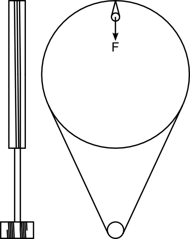
Thanks so much! I had a similar idea but they have really refined it. Here is what my basic setup up will be based on that idea. No friction required.
Edited 1 time(s). Last edit at 05/10/2013 01:53PM by nicholas.seward.
-------------------------------------------------------
> have you looked at kossels fishing lines pullys
> and the ideas behind?
> [www.youtube.com]
> the lines are fixed with screws on the wheel and
> doesn't depend on friction for driving the wheels
Thanks so much! I had a similar idea but they have really refined it. Here is what my basic setup up will be based on that idea. No friction required.

Edited 1 time(s). Last edit at 05/10/2013 01:53PM by nicholas.seward.
|
Re: Grounded Experimental Delta Printer May 10, 2013 03:50PM |
Registered: 10 years ago Posts: 979 |
Annirak Wrote:
-------------------------------------------------------
> Hah. Couldn't stop thinking about it so I did the
> math. You may have some trouble with the speed of
> the controller, because the coordinate
> transformation takes some heavy lifting as far as
> the math goes.
>
> ...
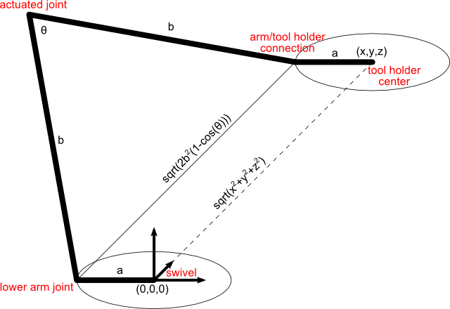
I haven't gone through to check your math but the geometry that I picked has the ability to greatly simplify the equations.
=x^{2}+y^{2}+z^{2})
)
Note: 2b2 is a constant so it can be hard coded. I don't know what the firmware can do yet but you could even store 1/2b2 instead to avoid division all together.
That equation for theta will work for all the arms. You have to just add or subtract constants from the x and y coordinate so that (0,0,0) coincides with the middle of each swivel.
By my math that comes out to...
12 multiplies
12 add/sub
3 acos
...for 1 position operation.
I would like to use a RasberryPI's GPIOs to interface straight to pololus and hall effect sensors. (I think this will get the total under $100 for the electronics.) Proof.
If that proves too problematic due to interrupt requests causing the steppers to stutter, can this be done on the printrboard or a mega? Which one would be better?
Edited 1 time(s). Last edit at 05/10/2013 03:50PM by nicholas.seward.
-------------------------------------------------------
> Hah. Couldn't stop thinking about it so I did the
> math. You may have some trouble with the speed of
> the controller, because the coordinate
> transformation takes some heavy lifting as far as
> the math goes.
>
> ...
I haven't gone through to check your math but the geometry that I picked has the ability to greatly simplify the equations.

Note: 2b2 is a constant so it can be hard coded. I don't know what the firmware can do yet but you could even store 1/2b2 instead to avoid division all together.
That equation for theta will work for all the arms. You have to just add or subtract constants from the x and y coordinate so that (0,0,0) coincides with the middle of each swivel.
By my math that comes out to...
12 multiplies
12 add/sub
3 acos
...for 1 position operation.
I would like to use a RasberryPI's GPIOs to interface straight to pololus and hall effect sensors. (I think this will get the total under $100 for the electronics.) Proof.
If that proves too problematic due to interrupt requests causing the steppers to stutter, can this be done on the printrboard or a mega? Which one would be better?
Edited 1 time(s). Last edit at 05/10/2013 03:50PM by nicholas.seward.
|
Re: Grounded Experimental Delta Printer May 10, 2013 05:09PM |
Registered: 15 years ago Posts: 401 |
nicholas.seward Wrote:
-------------------------------------------------------
> I haven't gone through to check your math but the
> geometry that I picked has the ability to greatly
> simplify the equations.
Your math and mine are equivalent. If you make the same assumptions with mine as with yours, you end up with the same math. I didn't make the a=a and b=b assumptions that you have made. That does result in a simplification, but it does restrict your design structurally. I also include the offsets you mention (subtracting x/y constants) up front. My math may be more complex, but it gives you more flexibility/fewer constraints in the mechanical design.
Your L-shaped brackets on the tool bearings also leads to a simplification. Are those done for rigidity in the toolhead or for simplification of the math? If just for the math, I would reconsider. My standpoint is that the hardware should be designed to be the best it can be, and the software should compensate, mathematically, for the complexity of the design. I understand your approach, but if the difference is a few additions or subtractions per position calculation... Go for the stronger physical design. Just my opinion; it's your design.
Anyway, I like your design.
|
Re: Grounded Experimental Delta Printer May 10, 2013 06:09PM |
Registered: 10 years ago Posts: 979 |
@Annirak: I agree whole-heatedly with the idea that math should be second to rigidity. However, I like how much easier the math is if all the arms connect on one plane. (I also think people will be more accepting of this but I don't really care about that.) I think that the rigidity differences between a 1 plane connection or a 3 plane connection would be academic. Anyway you cut it, those are easy parts to print over and over and over. (Speaking of that, is there anything else that you see that can be simplified?)
I also have to confess that I moved the two axes in the swivel an additional .3 inches apart to match the connection geometry of the holder. I am all about making a small change one place to make something else a lot easier.
I also have to confess that I moved the two axes in the swivel an additional .3 inches apart to match the connection geometry of the holder. I am all about making a small change one place to make something else a lot easier.
|
Re: Grounded Experimental Delta Printer May 10, 2013 06:38PM |
Registered: 10 years ago Posts: 979 |
New video
The 100% safe work envelope has been downgraded to 6x6x4.5". You can go much higher and much wider but you have to be careful that the wheels don't hit the part. I might need to write a gcode analyzer that will throw a warning if it would produce a collision. You could easily print an 11" Eiffel Tower or make a 8" diameter by 4" tall bowl.
The 100% safe work envelope has been downgraded to 6x6x4.5". You can go much higher and much wider but you have to be careful that the wheels don't hit the part. I might need to write a gcode analyzer that will throw a warning if it would produce a collision. You could easily print an 11" Eiffel Tower or make a 8" diameter by 4" tall bowl.
|
Re: Grounded Experimental Delta Printer May 10, 2013 06:38PM |
Registered: 15 years ago Posts: 401 |
I don't see anything obvious. I know it's extra weight, but Johann is moving from a bowden tube to an on-hotend extruder drive for Kossel because of the quality of the print. It's a consideration. I asked him about it; here was his answer.
Quote
Johann
I think it's much easier to get retraction working perfectly without a long Bowden tube. My goal is awesome print quality without too much hassle and endless calibration. I'm still testing the effector-mounted micro extruder, but my first results are looking pretty good.
|
Re: Grounded Experimental Delta Printer May 10, 2013 06:52PM |
Registered: 10 years ago Posts: 979 |
I would definitely rather not have a bowden tube. A local company, QU-BD, is making a printer with a 170g complete unit.
I am a high school teacher and our school was in the market for a printer. I found theirs and they are only 1 hour down the road. However, the printer sounded too good to be true. I was dubious at first so I scheduled a field trip with my kids and we went and checked out their facility. They are awesome engineers and did not over state anything. Moral of the story, I am happily waiting on the Revolution. They are so nice that they want to come and help get us setup personally instead of mailing the printer. I think I might coordinate with them. It will be hard to beat 170g. (The 170g extruder is not the MBE extruder that they had on kickstarter. They are definitely evolving.)
Thanks for bringing that up. I thought bowden was the way of the future but if Johann is going away from it then that gives me some pause.
Edited 1 time(s). Last edit at 05/10/2013 10:25PM by nicholas.seward.
|
Re: Grounded Experimental Delta Printer May 11, 2013 12:50AM |
Registered: 12 years ago Posts: 23 |
I am not giving up on Bowden just yet. The latest version of Slic3r has quite a couple of quality enhancing features built in, and the prints I am doing today are not displaying the endless oozing and stringing and blobbing of my first attempts in February.
Remember that Kossel is a seriously beefed up Rostock, and the move may not agree with your vitamin hunt.
Remember that Kossel is a seriously beefed up Rostock, and the move may not agree with your vitamin hunt.
|
Re: Grounded Experimental Delta Printer May 11, 2013 04:39AM |
Registered: 15 years ago Posts: 401 |
|
Re: Grounded Experimental Delta Printer May 11, 2013 08:32AM |
Registered: 10 years ago Posts: 979 |
Annirak Wrote:
-------------------------------------------------------
> I think I may have an optimization for your
> design, which also gets rid of the arccos. I was
> thinking about the wheels impinging on the work
> area and I have an idea which will replace them
> with a pair of pulleys and a cantilevered beam.
> I'll try to get it drawn up and posted here later.
The wheels essentially cut into the work envelope by 2 inches on each side. I eagerly await your idea. Easier math and a enormous envelope sound good to me.
I printed one frame piece last night. It just made this more real.
|
Re: Grounded Experimental Delta Printer May 11, 2013 08:40AM |
Registered: 10 years ago Posts: 979 |
qharley Wrote:
-------------------------------------------------------
> I am not giving up on Bowden just yet. The latest
> version of Slic3r has quite a couple of quality
> enhancing features built in, and the prints I am
> doing today are not displaying the endless oozing
> and stringing and blobbing of my first attempts in
> February.
>
> Remember that Kossel is a seriously beefed up
> Rostock, and the move may not agree with your
> vitamin hunt.
I won't count bowden out yet. I will need a tube that is 20+ inches long. That seems very long to me. How long is Morgan's tube?
|
Re: Grounded Experimental Delta Printer May 11, 2013 05:11PM |
Registered: 15 years ago Posts: 401 |
Okay, this is going to be a long post.
I should make clear before I go any further that this didn't work out quite how I wanted. I was looking for a simple geometry that would work along the same lines, but it didn't come out how I wanted. It will still work, but the math becomes more complex, not less. That is, unless you turn it the other way up and suspend the arms over the work surface. Then, the math becomes trivial. Nope, it's pretty simple in both cases. See below.
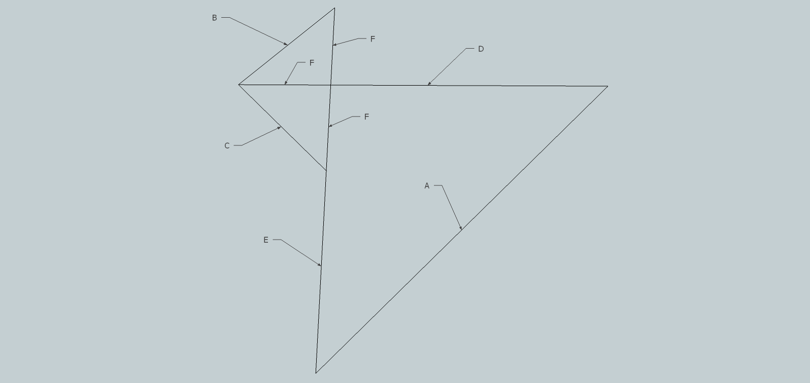
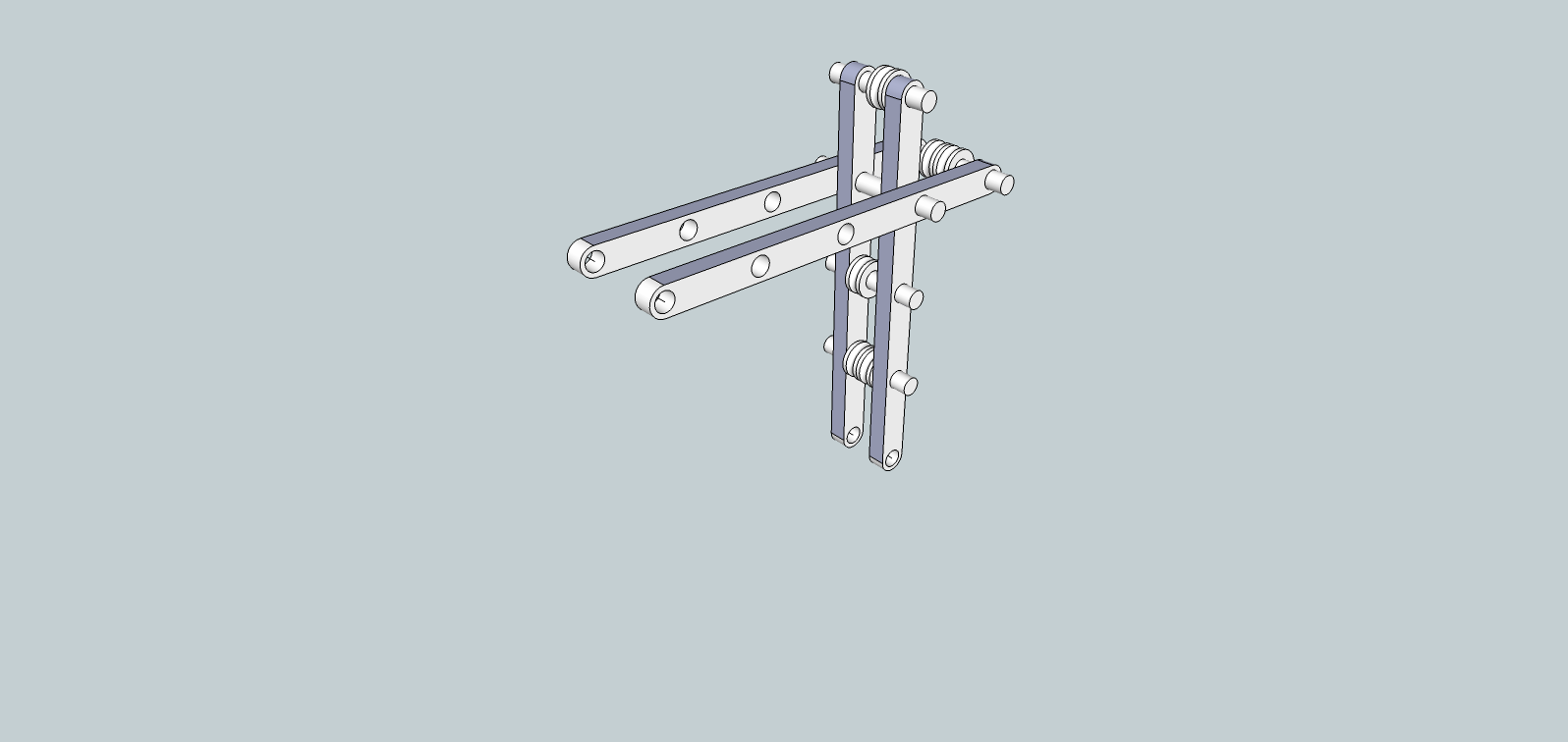
First, here's the simplified geometry:
A is the length we're trying to control.
The intersection of D and E is the elbow joint.
D=E
B is both parallel and proportional to A.
B & C are 80 lb test line.
Since B+C is not constant, B needs to be fitted with a spring. Strictly speaking, B is not necessary for acceleration less than 1g.
a = arccos ( 1 - A^2/(2D^2) )
C = sqrt ( 2D^2 * ( 1 - cos(180 - a) ) )
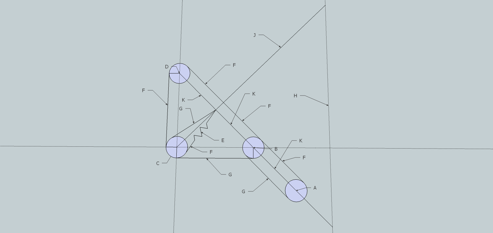
Here's the same drawing again, but with more of the detail drawn in.
A is the drive pulley.
B, C, and D are freewheeling pulleys.
E is the spring.
F and G are line.
K and J are the beams.
Here's a 3D view of it.
If you turn the whole assembly upside down, the tensioning gets swapped and the math becomes trivial. I don't know if any of this made sense, but it seems roughly right.
Edited 3 time(s). Last edit at 05/12/2013 08:48AM by Annirak.
First, here's the simplified geometry:

A is the length we're trying to control.
The intersection of D and E is the elbow joint.
D=E
B is both parallel and proportional to A.
B & C are 80 lb test line.
Since B+C is not constant, B needs to be fitted with a spring. Strictly speaking, B is not necessary for acceleration less than 1g.
a = arccos ( 1 - A^2/(2D^2) )
C = sqrt ( 2D^2 * ( 1 - cos(180 - a) ) )
Here's the same drawing again, but with more of the detail drawn in.

A is the drive pulley.
B, C, and D are freewheeling pulleys.
E is the spring.
F and G are line.
K and J are the beams.
Here's a 3D view of it.

If you turn the whole assembly upside down, the tensioning gets swapped and the math becomes trivial. I don't know if any of this made sense, but it seems roughly right.
Edited 3 time(s). Last edit at 05/12/2013 08:48AM by Annirak.
|
Re: Grounded Experimental Delta Printer May 11, 2013 07:22PM |
Registered: 12 years ago Posts: 23 |
|
Re: Grounded Experimental Delta Printer May 11, 2013 09:28PM |
Registered: 10 years ago Posts: 979 |
Annirak Wrote:
-------------------------------------------------------
> Okay, this is going to be a long post.
>
> I should make clear before I go any further that
> this didn't work out quite how I wanted. I was
> looking for a simple geometry that would work
> along the same lines, but it didn't come out how I
> wanted. It will still work, but the math becomes
> more complex, not less. That is, unless you turn
> it the other way up and suspend the arms over the
> work surface. Then, the math becomes trivial.
> ...
That is an awesome idea! I have an idea for a variant that will work pretty good for Simpson. Instead of explaining I am going to draw it up. I expect to use this geometry. Wheels suck!
|
Re: Grounded Experimental Delta Printer May 12, 2013 04:36AM |
Registered: 10 years ago Posts: 979 |
I have been working hard on the 2nd major redesign of Simpson. The design will utilize Annirak's genius. If you look at his first diagram, I will have a block and tackle setup along B and an extension spring roughly along C. I will have the string make 2 round trips along B to give me a mechanical advantage of 4. I am going to make E=8" and F=2". These numbers I hit upon happened to produce an amazing result that I didn't need but it sure is neat. The result is that if the motor pulls the string 1" then the tool gets 1" closer to the swivel. Annirak, what a great idea!
If I get a 60oz-in stepper then I can generate a net tension along B of 30lbf. I sourced a spring that will apply 10-20lbf in its working range. That translates to about a 2.5-5lbf from each arm. (These are napkin estimates. Do not check me too close.) If I can get the effective mass under 1-2 pounds (not a problem) then I have the potential to produce >5g's. Of course, I would have to bolt it to the table or it would start jumping away. Probably more importantly, speeds of over 500mm/s are possible. (This is all academic until the robot is built.)
I have also printed out the frame and the swivels. Here is a picture with a bunch of rejects in the background. I mostly got some hard lessons in how you should orient you part for max strength. I am still pretty new to 3D printing. All and all, I am pretty happy so far. Everything is super rigid and smooth like butter. I can't wait to get the arms done but the new design calls for a 9"-10" arm and my printer can do 8". I can't really shorten it unless I make the frame smaller. Oh well, I might get them laser cut and reprint them when Simpson is working.
Okay, back to CAD.
Side note: Too many bearings. My bearing count is up to 42 counting the extruder. Luckily most are 40 cents a piece. The tool holder bearings are $8 and the block and tackle bearings are going to be about $1. That brings the total to about $60 for all the bearings. For comparison, it would be near impossible to get all the rails, rods, and bearings for a cartesian bot for less than $100. This is shaping up to be a step forward in price, work envelope, and hopefully speed with stupid simple inverse kinematics that anything can handle. I am so excited. VXB, McMaster-Carr,RasperryPi,Pololu,SteppersOnline here I come.
Edited 1 time(s). Last edit at 05/12/2013 05:08AM by nicholas.seward.
If I get a 60oz-in stepper then I can generate a net tension along B of 30lbf. I sourced a spring that will apply 10-20lbf in its working range. That translates to about a 2.5-5lbf from each arm. (These are napkin estimates. Do not check me too close.) If I can get the effective mass under 1-2 pounds (not a problem) then I have the potential to produce >5g's. Of course, I would have to bolt it to the table or it would start jumping away. Probably more importantly, speeds of over 500mm/s are possible. (This is all academic until the robot is built.)

I have also printed out the frame and the swivels. Here is a picture with a bunch of rejects in the background. I mostly got some hard lessons in how you should orient you part for max strength. I am still pretty new to 3D printing. All and all, I am pretty happy so far. Everything is super rigid and smooth like butter. I can't wait to get the arms done but the new design calls for a 9"-10" arm and my printer can do 8". I can't really shorten it unless I make the frame smaller. Oh well, I might get them laser cut and reprint them when Simpson is working.
Okay, back to CAD.
Side note: Too many bearings. My bearing count is up to 42 counting the extruder. Luckily most are 40 cents a piece. The tool holder bearings are $8 and the block and tackle bearings are going to be about $1. That brings the total to about $60 for all the bearings. For comparison, it would be near impossible to get all the rails, rods, and bearings for a cartesian bot for less than $100. This is shaping up to be a step forward in price, work envelope, and hopefully speed with stupid simple inverse kinematics that anything can handle. I am so excited. VXB, McMaster-Carr,RasperryPi,Pololu,SteppersOnline here I come.
Edited 1 time(s). Last edit at 05/12/2013 05:08AM by nicholas.seward.
|
Re: Grounded Experimental Delta Printer May 12, 2013 08:44AM |
Registered: 15 years ago Posts: 401 |
|
Re: Grounded Experimental Delta Printer May 12, 2013 10:42AM |
Registered: 15 years ago Posts: 401 |
|
Re: Grounded Experimental Delta Printer May 12, 2013 10:52AM |
Registered: 10 years ago Posts: 979 |
Annirak Wrote:
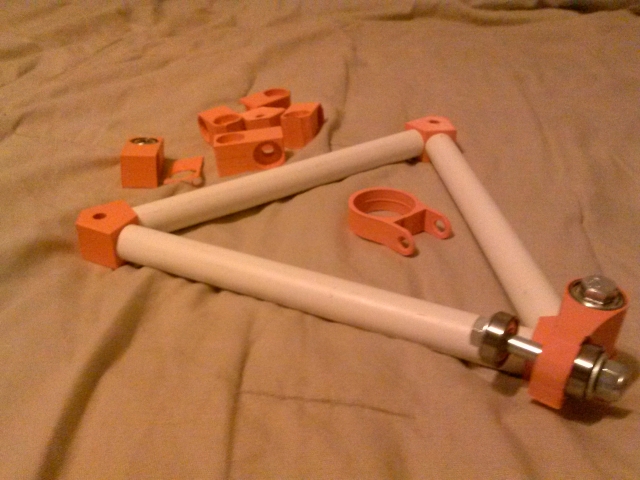
-------------------------------------------------------
> Well, I rigged up a test with meccano. It looks
> like the spring is going to be a problem. A
> constant-force spring would solve the problem
> nicely, though
I thought about constant-force. I initially ruled it out due to price but it isn't that expensive.
What kind of problems did you have with the spring? My problems on paper are that you can't get close to the 0 or 180 positions. That does limit the work envelope but not by much.
|
Re: Grounded Experimental Delta Printer May 12, 2013 05:53PM |
Registered: 15 years ago Posts: 401 |
The problem with the spring is just the range of force required to move it. When the arm is at either extreme, the line is short and the spring is compressed. When the arm is in the middle, the line is long and the spring is extended.
Because F=kx, if you want a reasonable force at the extremes, the force in the middle is quite large.
Constant force springs are just coiled up leaf springs with a very small k and a prebiased x. You could probably pull one that would do the job out of a tape measure.
The spring goes through an expansion of 2*(sqrt(2)-1)*F over the full range of motion.
Here's how it works out on the meccano arm. You can see that the spring overcomes the motor quite easily.
|
Re: Grounded Experimental Delta Printer May 12, 2013 08:18PM |
Registered: 10 years ago Posts: 979 |
Annirak Wrote:
-------------------------------------------------------
> The problem with the spring is just the range of
> force required to move it. When the arm is at
> either extreme, the line is short and the spring
> is compressed. When the arm is in the middle, the
> line is long and the spring is extended.
>
> Because F=kx, if you want a reasonable force at
> the extremes, the force in the middle is quite
> large.
>
> Constant force springs are just coiled up leaf
> springs with a very small k and a prebiased x.
> You could probably pull one that would do the job
> out of a tape measure.
>
> The spring goes through an expansion of
> 2*(sqrt(2)-1)*F over the full range of motion.
>
> Here's how it works out on the meccano arm. You
> can see that the spring overcomes the motor quite
> easily.
Okay, I see what you are talking about. (Thanks so much for making a video. I am jealous of your meccano's.) I think I have a solution. I am going to use this spring. Currently, I am going with F=2" and E=8". That gives me a max working range of 4 inches (less if you give 0 degrees and 180 degrees a little breathing room which I will) on the spring. The spring I picked has a usable range of 6 inches. (4.5"-10.4") With a k of 4lbs/in, the springs force will vary by 16lbs from extreme to extreme. If I pick my mount point right, I can make that range 8-24lbs. Now the question is, can the string pull against such a large force? If I use a block and tackle setup along B then I get a mechanical advantage of 4 and the stepper only has to generate a tension in the wire between 2-6lbs. A 60oz-in stepper with a .5" diameter drive pulley can generate up to 15lbs. That is good to know since I can now run my steppers at half power to keep them cool and still get the job done. (It is right on the edge of Nema14. I am still hoping to do this but I am going to table that until I get a testing platform.)
I am ordering the springs and am going to have to mill or laser cut my arms. I am so close to being able to print them but oh well. I should have the parts ready for when the springs arrive so I can do a quick test to see if I am full of it. I will post a video when I do. I am getting closer on the CAD. I should be able to post a a decent mock up soon.
Edited 1 time(s). Last edit at 05/12/2013 08:51PM by nicholas.seward.
|
Re: Grounded Experimental Delta Printer May 13, 2013 05:10AM |
Registered: 10 years ago Posts: 979 |
I have been agonizing over the extruder setup as of late. I have been waffling between 3 options: 1) Bowden, 2) Lightweight all-in-one unit, and 3) Flexible shaft driving a hobbed bolt on the effector.
Option 3 is not proven. I would like to get this flexible shaft. The one that is .187x20". It costs $130 and still the shaft will have an angular deflection while loaded of 5 degrees over the 20". The slope comes out to be .2mm of filament. Not too shabby. I have seen someone idea that uses a speedo cable. That brings the cost down to $15 or less if you go to the junk yard. The deflection has to be a lot more but you can go up to 30ish degrees and stay under 1mm of play. Slic3r can handle that no problem. My current opinion is that this has potential but the complexity is not worth the possible gain.
Option 2 is still on the table. I contact QU-BD and they are hooking me up with one of their small extruders before it hits the market. I haven't gotten it yet so I am not sure how it will fit into the design.
Option 1 is what I am going to do. Everything about Simpson screams symmetry and nothing says symmetry like bowden. Bowden tubes work and they are light. (It sounds like an easy decision but it wasn't.)

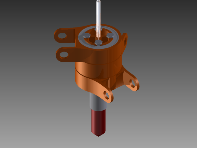
Here is the design of the effector. There are some neat features. Every arms connection can rotate independent of the others. There is room for wires to go through. The bolts cause radial pressure on the bowden tube and the extruder. This unit should have zero play. It is also printable without any support structure. Check out the exploded assembly video below.
Extruder Assembly Video
Other news: I have most of the rest of Simpson CADed out but I am obsessing over small things. I am designing plastic arms but I am going to have to make another version with wooden arms for now. The arms are nothing special. I can just use flatstock with various holes arrayed along the central axis. I wish I had a big enough printer to do the plastic arms first.
Edited 3 time(s). Last edit at 05/13/2013 12:50PM by nicholas.seward.
Option 3 is not proven. I would like to get this flexible shaft. The one that is .187x20". It costs $130 and still the shaft will have an angular deflection while loaded of 5 degrees over the 20". The slope comes out to be .2mm of filament. Not too shabby. I have seen someone idea that uses a speedo cable. That brings the cost down to $15 or less if you go to the junk yard. The deflection has to be a lot more but you can go up to 30ish degrees and stay under 1mm of play. Slic3r can handle that no problem. My current opinion is that this has potential but the complexity is not worth the possible gain.
Option 2 is still on the table. I contact QU-BD and they are hooking me up with one of their small extruders before it hits the market. I haven't gotten it yet so I am not sure how it will fit into the design.
Option 1 is what I am going to do. Everything about Simpson screams symmetry and nothing says symmetry like bowden. Bowden tubes work and they are light. (It sounds like an easy decision but it wasn't.)

Here is the design of the effector. There are some neat features. Every arms connection can rotate independent of the others. There is room for wires to go through. The bolts cause radial pressure on the bowden tube and the extruder. This unit should have zero play. It is also printable without any support structure. Check out the exploded assembly video below.
Extruder Assembly Video
Other news: I have most of the rest of Simpson CADed out but I am obsessing over small things. I am designing plastic arms but I am going to have to make another version with wooden arms for now. The arms are nothing special. I can just use flatstock with various holes arrayed along the central axis. I wish I had a big enough printer to do the plastic arms first.
Edited 3 time(s). Last edit at 05/13/2013 12:50PM by nicholas.seward.
|
Re: Grounded Experimental Delta Printer May 13, 2013 05:44AM |
Registered: 10 years ago Posts: 979 |
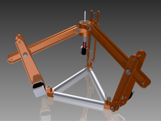
I couldn't contain myself. Here is a snapshot of the 3rd redesign of Simpson. He is looking pretty good. I need to add in some string, springs, magnets, hall effect sensors, spacers, bolts, and nuts. The spring will attach to the short side of the upper arm and extend down to somewhere close to the stepper. The two short ends of the arms will be pulled together with a block and tackle setup.
Now...must...sleep...
Edited 1 time(s). Last edit at 05/13/2013 05:45AM by nicholas.seward.

Now...must...sleep...
Edited 1 time(s). Last edit at 05/13/2013 05:45AM by nicholas.seward.
|
Re: Grounded Experimental Delta Printer May 13, 2013 09:07AM |
Registered: 11 years ago Posts: 265 |
Couldn't all the cons of a bowden be solved by a small light incremental encoder at the hotend?
So many joints,
I think the number of tolerances will add up, and I'm worried you will have a tough time getting 1mm accuracy at the tool end.
Interesting project though, keep going!
Edited 1 time(s). Last edit at 05/13/2013 09:10AM by ShadowRam.
So many joints,
I think the number of tolerances will add up, and I'm worried you will have a tough time getting 1mm accuracy at the tool end.
Interesting project though, keep going!
Edited 1 time(s). Last edit at 05/13/2013 09:10AM by ShadowRam.
|
Re: Grounded Experimental Delta Printer May 13, 2013 10:11AM |
Registered: 15 years ago Posts: 401 |
I think I may have come up with a way to get rid of the spring. It means adding another piece to the arm. I'm not convinced this is a good idea. My test showed it performing well on the lift, but poorly on the drop. This would probably be helped by gravity on the toolhead.
I also can't tell how much force can be exerted at either end, though the force in the middle of the range should be decent.
The idea is to add what amounts to a linear actuator between the two arms.
I think it would perform better on the drop if it had a decently powered motor, not this puny meccano motor.
Edited 1 time(s). Last edit at 05/13/2013 12:45PM by Annirak.
|
Re: Grounded Experimental Delta Printer May 13, 2013 11:06AM |
Registered: 10 years ago Posts: 979 |
ShadowRam Wrote:
-------------------------------------------------------
> Couldn't all the cons of a bowden be solved by a
> small light incremental encoder at the hotend?
>
> So many joints,
>
> I think the number of tolerances will add up, and
> I'm worried you will have a tough time getting 1mm
> accuracy at the tool end.
>
> Interesting project though, keep going!
Brilliant idea! That could easily be done. I am going to design something up and put it inside the effector but not worry about using it right away. (This reminds me of an XKCD where a guy asks for a USB port to be installed during a surgery. He argues the firmware can be updated later.)
I was worried about tolerances adding up. ...but... I built some parts and I am hard pressed to see any wobble. Remember that a lot of the ways that this bot can and will wobble don't really affect the separation distance that we are trying to drive. Rigidity is high along the arm plane but very bad normal to it. That is okay because a slight normal displacement doesn't really affect the driven separation. (Check back in a week or two and I should have a full assembly sans motors to check for rigidity.)
Edited 1 time(s). Last edit at 05/13/2013 11:49AM by nicholas.seward.
-------------------------------------------------------
> Couldn't all the cons of a bowden be solved by a
> small light incremental encoder at the hotend?
>
> So many joints,
>
> I think the number of tolerances will add up, and
> I'm worried you will have a tough time getting 1mm
> accuracy at the tool end.
>
> Interesting project though, keep going!
Brilliant idea! That could easily be done. I am going to design something up and put it inside the effector but not worry about using it right away. (This reminds me of an XKCD where a guy asks for a USB port to be installed during a surgery. He argues the firmware can be updated later.)

I was worried about tolerances adding up. ...but... I built some parts and I am hard pressed to see any wobble. Remember that a lot of the ways that this bot can and will wobble don't really affect the separation distance that we are trying to drive. Rigidity is high along the arm plane but very bad normal to it. That is okay because a slight normal displacement doesn't really affect the driven separation. (Check back in a week or two and I should have a full assembly sans motors to check for rigidity.)
Edited 1 time(s). Last edit at 05/13/2013 11:49AM by nicholas.seward.
|
Re: Grounded Experimental Delta Printer May 13, 2013 11:15AM |
Registered: 10 years ago Posts: 979 |
Annirak Wrote:
-------------------------------------------------------
> I think I may have come up with a way to get rid
> of the spring. It means adding another piece to
> the arm. I'm not convinced this is a good idea.
> My test showed it performing well on the lift, but
> poorly on the drop. This would probably be helped
> by gravity on the toolhead.
>
> I also can't tell how much force can be exerted at
> either end, though the force in the middle of the
> range should be decent.
>
> The
> url=https://www.youtube.com/watch?v=VVecj6CaC3s]id
> ea is to add what amounts to a linear actuator
> between the two arms.
>
> I think it would perform better on the drop if it
> had a decently powered motor, not this puny
> meccano motor.
I like it but I would need a linear rod on the upper arm to get the precision that I want. There is no way to keep the string straight without infinite tension. I will keep thinking on it. I am still loving your previous idea.
|
Re: Grounded Experimental Delta Printer May 13, 2013 08:30PM |
Registered: 10 years ago Posts: 979 |

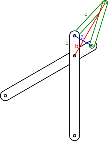
I came up with an improvement that can get rid of the the big spring. I was thinking about the arrangement above with strings in tension along a and b. Ideally a+b would be a constant but that only works if c/d is infinity. However, I did happen to notice that as c/d increased the amount that a+b would vary over the range of motion would decrease. This got me thinking that maybe I would set a+b as a constant and then spring load c with small compression springs. As just a test I picked a+b=8" and d=2". In this case c would range from 4" to 4.5". That is hardly a difference at all. It will be easy to pick a spring that can produce virtually a constant force over the range of motion. This spring can be used to produce a 11-15lb force over the range of motion. I am sure I can find better. That was just the first workable one I saw. 15lbs is my max. With a .5" drive pulley and a 4 string block and tackle setup along a and b, I can generate 30lbs at most so 15lbs per c.
The beauty of this system is that you can adjust a+b. This will allow me to pick a perfect preload for the springs. I don't have to get the calculations perfect now.
I know this is one more joint and a complex string routing system but let me know what you think. I personally think this is the winner so far. I will CAD it up so better judgement can take place.
Thanks,
Nicholas Seward
Edited 1 time(s). Last edit at 05/13/2013 08:31PM by nicholas.seward.
|
Re: Grounded Experimental Delta Printer May 14, 2013 11:02AM |
Registered: 10 years ago Posts: 979 |
I just realized that if I go with the quad-link arm above that Simpson will look like Bart Simpson. I am ordering yellow filament.
Update: I have ordered all the non-printed parts. The printing is going great. I just have to finalize the quad-link design and get some oversized parts laser cut.
Update: I have ordered all the non-printed parts. The printing is going great. I just have to finalize the quad-link design and get some oversized parts laser cut.


Sorry, only registered users may post in this forum.