Grounded Experimental Delta Printer
Posted by nicholas.seward
|
Re: Grounded Experimental Delta Printer June 21, 2013 09:02AM |
Registered: 10 years ago Posts: 86 |
|
Re: Grounded Experimental Delta Printer June 21, 2013 11:57AM |
Registered: 11 years ago Posts: 24 |
[www.youtube.com]
Just found your vid. Its pretty cool! Love it!
Btw I noticed you have motors on the arm itself, don't you want to keep the weight of the arms down, by relocating the motor elsewhere?
On a previous thread, I was talking about printing twice the size of the printer using a forklift mechanism. I wonder if your design has any potential to be modified to print twice its size. (e.g. maybe a sissor lift?)
Edited 2 time(s). Last edit at 06/21/2013 12:07PM by mofosyne.
|
Re: Grounded Experimental Delta Printer June 21, 2013 02:11PM |
To true up the print head you can drop the ears (clearing the center ring) of the top ring mount to the center position. And raise up the ears of the bottom mount in the same way. This would place the pivots on the same plane. If the head is not kept level the material will not be extruded the same in all positions.
|
Re: Grounded Experimental Delta Printer June 21, 2013 02:51PM |
Registered: 10 years ago Posts: 979 |
|
Re: Grounded Experimental Delta Printer June 22, 2013 11:13AM |
Registered: 10 years ago Posts: 979 |
mofosyne Wrote:
-------------------------------------------------------
> Btw I noticed you have motors on the arm itself,
> don't you want to keep the weight of the arms
> down, by relocating the motor elsewhere?
I put them on the arm for simplicity of build. They ended up not being a problem. I estimate that I can get a faster nimbler bot if I replace the steppers with NEMA14's instead of NEMA17's. It is an interesting problem. I have more than enough power but the acceleration has to be limited because of all the arm inertia. A NEMA14 has 1/3 the power and 1/3 the weight which should allow for a higher acceleration setting.
|
Re: Grounded Experimental Delta Printer June 24, 2013 05:56AM |
Registered: 15 years ago Posts: 401 |
nicholas.seward Wrote:
-------------------------------------------------------
> @Efxjim. The print head stays true as is. The
> geometry dictates that. The offsets on the
> central hub could be removed but it would increase
> the complexity and slightly reduce the rigidity.
> Additionally, software can make the adjustments
> for the offsets with some simple addition.
Precisely. This was one of the debates we had early on. Where small changes to software can make the hardware better, it's worthwhile.
nicholas.seward Wrote:
-------------------------------------------------------
> mofosyne Wrote:
> --------------------------------------------------
> -----
> > Btw I noticed you have motors on the arm
> itself,
> > don't you want to keep the weight of the arms
> > down, by relocating the motor elsewhere?
>
> I put them on the arm for simplicity of build.
> They ended up not being a problem. I estimate
> that I can get a faster nimbler bot if I replace
> the steppers with NEMA14's instead of NEMA17's.
> It is an interesting problem. I have more than
> enough power but the acceleration has to be
> limited because of all the arm inertia. A NEMA14
> has 1/3 the power and 1/3 the weight which should
> allow for a higher acceleration setting.
The routing of the drive cables becomes more complex if the motors are not mounted on the arm. This is one situation where updating the software to compensate for making the hardware higher performance would likely not work well: the hardware complexity for moving the motor off of the arm is bad.
-------------------------------------------------------
> @Efxjim. The print head stays true as is. The
> geometry dictates that. The offsets on the
> central hub could be removed but it would increase
> the complexity and slightly reduce the rigidity.
> Additionally, software can make the adjustments
> for the offsets with some simple addition.
Precisely. This was one of the debates we had early on. Where small changes to software can make the hardware better, it's worthwhile.
nicholas.seward Wrote:
-------------------------------------------------------
> mofosyne Wrote:
> --------------------------------------------------
> -----
> > Btw I noticed you have motors on the arm
> itself,
> > don't you want to keep the weight of the arms
> > down, by relocating the motor elsewhere?
>
> I put them on the arm for simplicity of build.
> They ended up not being a problem. I estimate
> that I can get a faster nimbler bot if I replace
> the steppers with NEMA14's instead of NEMA17's.
> It is an interesting problem. I have more than
> enough power but the acceleration has to be
> limited because of all the arm inertia. A NEMA14
> has 1/3 the power and 1/3 the weight which should
> allow for a higher acceleration setting.
The routing of the drive cables becomes more complex if the motors are not mounted on the arm. This is one situation where updating the software to compensate for making the hardware higher performance would likely not work well: the hardware complexity for moving the motor off of the arm is bad.
|
Re: Grounded Experimental Delta Printer June 29, 2013 02:03AM |
Registered: 10 years ago Posts: 979 |
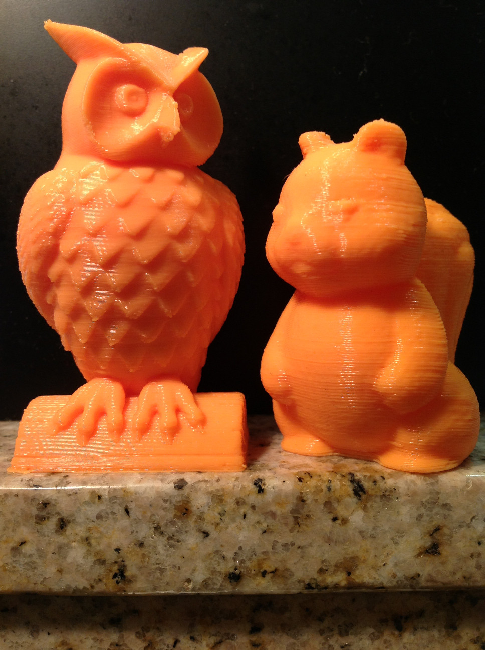
Here is a youtube timelapse video of Simpson printing an owl. I have a picture of the printed owl below with my earlier squirrel for comparison. The owl came off perfect with only a few small things that took 15 seconds to get off with a fingernail. If I remember right the squirrel was printed with a .25mm layer height and the owl with a .2mm layer height. I used the default speed settings in Slic3r 0.9.9. There was no stringing/oozing that plagues most bowden setups.
Edited 3 time(s). Last edit at 06/29/2013 02:34AM by nicholas.seward.


Edited 3 time(s). Last edit at 06/29/2013 02:34AM by nicholas.seward.
|
Re: Grounded Experimental Delta Printer June 29, 2013 08:15AM |
Registered: 11 years ago Posts: 3 |
nicholas.seward Wrote:
-------------------------------------------------------
> mofosyne Wrote:
> --------------------------------------------------
> -----
> > Btw I noticed you have motors on the arm
> itself,
> > don't you want to keep the weight of the arms
> > down, by relocating the motor elsewhere?
>
> I put them on the arm for simplicity of build.
> They ended up not being a problem. I estimate
> that I can get a faster nimbler bot if I replace
> the steppers with NEMA14's instead of NEMA17's.
> It is an interesting problem. I have more than
> enough power but the acceleration has to be
> limited because of all the arm inertia. A NEMA14
> has 1/3 the power and 1/3 the weight which should
> allow for a higher acceleration setting.
Hello,
i'm a mechanical engineer and from looking at your very interesting and very nice design i can tell that only a small part from the complete inertia comes from the steppers weight. So, if you go to smaller steppers like 1/3 force and 1/3 weight you will loose acceleration capability. Most of the inertia comes from everything connected to the end of the first arm.
If you want to lower your inertia without loosing rigidity there are severall possibilities. Easiest was to lower the position of the steppers more close to the lowest horizontal joint close to the vertical axis. May be you want to turn the steppers by 45°. A more complex approach was to mount the steppers at the triangle very close to the vertical axis. But, as Annirak says, the routing of the drive cabels will be difficult.
|
Re: Grounded Experimental Delta Printer June 30, 2013 08:23PM |
Registered: 10 years ago Posts: 979 |
Nema17 motors are way oversized for this. I can get all the acceleration I need from a Nema14.
You are right that motors don't add much but I can assure you they contribute the majority of the ineritia. The other parts may look big but they are super light low infill parts.
Side note: when I print fast and the elbows flop around the print quality doesn't suffer so decreasing inertia is only to keep from freaking people out.
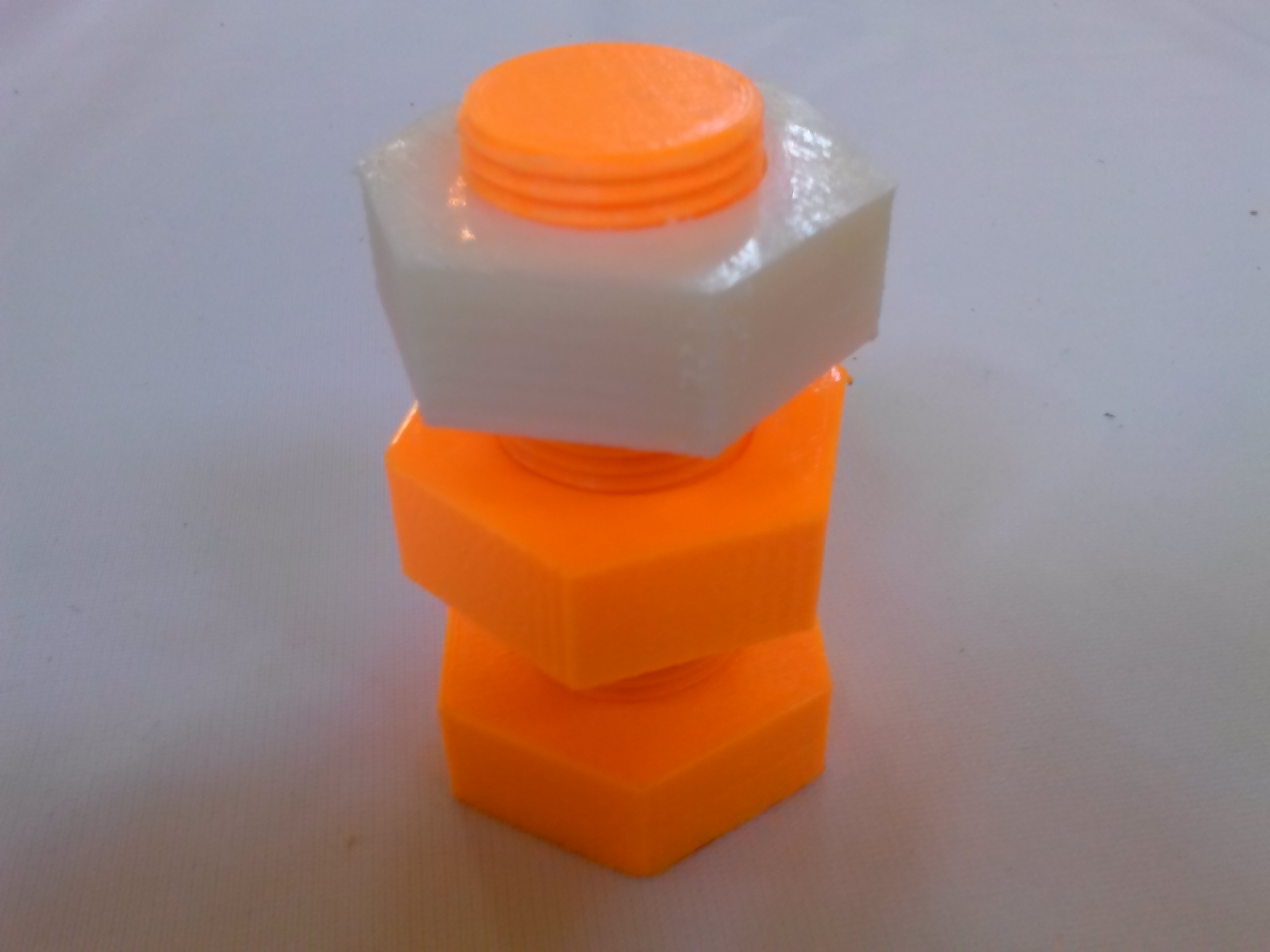
I attached a picture of a nut and bolt that I printed at the KC Maker Faire this weekend. I would push 5mm on the elbows about every minute to prove to people that the floppy arms didn't hut the print quality. Equally exciting is that the white nut in the picture was printed on a QU-BD machine and the fit together like a glove. I think I am ready to start doing self replication prints.
You are right that motors don't add much but I can assure you they contribute the majority of the ineritia. The other parts may look big but they are super light low infill parts.
Side note: when I print fast and the elbows flop around the print quality doesn't suffer so decreasing inertia is only to keep from freaking people out.
I attached a picture of a nut and bolt that I printed at the KC Maker Faire this weekend. I would push 5mm on the elbows about every minute to prove to people that the floppy arms didn't hut the print quality. Equally exciting is that the white nut in the picture was printed on a QU-BD machine and the fit together like a glove. I think I am ready to start doing self replication prints.
|
Re: Grounded Experimental Delta Printer July 01, 2013 08:34AM |
Registered: 10 years ago Posts: 979 |
For people that are skeptical about Simpson's print quality. Here is a time lapse of a whole day of Simpson printing at the Kansas City Maker Faire. You can't see it but I was located on a table with the QU-BD printers which shake the table a fair amount. I also demonstrated the stability (wobble tolerance) by pushing on the elbows every couple of minutes for nonbelievers. I think there are some artifacts in the print for sure but they are very subtle.
http://www.youtube.com/watch?v=Aytfhr2DeeM
The white nut was printed on a QU-BD Revolution XL. The orange parts are mine. They fit together like they were printed on the same machine. Again, I was super mean to Simpson while he was printing this.
Edited 2 time(s). Last edit at 07/01/2013 08:37AM by nicholas.seward.
http://www.youtube.com/watch?v=Aytfhr2DeeM

The white nut was printed on a QU-BD Revolution XL. The orange parts are mine. They fit together like they were printed on the same machine. Again, I was super mean to Simpson while he was printing this.
Edited 2 time(s). Last edit at 07/01/2013 08:37AM by nicholas.seward.
|
Re: Grounded Experimental Delta Printer July 01, 2013 09:31AM |
Registered: 10 years ago Posts: 979 |
I just launched a website.
ConceptFORGE
There is no content on the site (yet) but you can submit your email on it and I will make sure those that do will be the first to be offered a chance to get beta Simpson kits. I am going to push for a shipping date before Christmas and a cost under $500 but I am only in the early planning stages so nothing is for sure.
The beta kit will have some form of auto-calibration so it will be suitable for everyday use.
|
Re: Grounded Experimental Delta Printer July 01, 2013 11:47AM |
Registered: 11 years ago Posts: 102 |
|
Re: Grounded Experimental Delta Printer July 01, 2013 12:02PM |
Registered: 10 years ago Posts: 979 |
|
Re: Grounded Experimental Delta Printer July 04, 2013 03:26AM |
|
Re: Grounded Experimental Delta Printer July 04, 2013 05:25AM |
Registered: 10 years ago Posts: 979 |
That is very exciting!
Thingiverse:
[www.thingiverse.com]
BOM:
[www.thingiverse.com]
You need any filament drive (moded or designed for bowden.).
Each arm is driven by one motor each. You can use any Nema14 or Nema17 that you can drive with your electronics of choice. Look at the BOM if you need more direction. Unless I made a mistake (very possible) it has everything detailed down to the nut along with vendor links.
I used an azteeg x1 but any of the reprap electronic packages should work just fine. (Arduino/Ramps, Printrboard, Sanguino)
Please, ask as many questions as you need while you are going through this process. I need motivation to increase the quality of the documentation.
|
Re: Grounded Experimental Delta Printer July 04, 2013 07:09AM |
Well, i will not make it tomorrow ^^' I am making a phd in computer science, and so I don't have so much time (neither money) to build it right now. But I am very interested. Thanks a lot for the explanations and documentations, and also to pass time to design and share this printer.
Also, I have some raspberry pi at home, and i'm now investigating the possibility to use that insteed of a controller that we have to build. I think it may be easier and cheaper. I saw on the french forum that someone is already adapting a raspberry pi for another reprap.
Also, I have some raspberry pi at home, and i'm now investigating the possibility to use that insteed of a controller that we have to build. I think it may be easier and cheaper. I saw on the french forum that someone is already adapting a raspberry pi for another reprap.
|
Re: Grounded Experimental Delta Printer July 04, 2013 07:27AM |
Registered: 15 years ago Posts: 401 |
The Raspberry Pi, while an excellent little computer, doesn't really have the peripherals you need to drive a reprap. It has too few GPIO for endstops, stepper drivers, and heater. It doesn't have an analog input for the temperature sensor.
You can get around needing a PWM for the heater by using bang-bang control, but that gives you less temperature stability. You can use GPIO expansion via SPI to get around most of this. You can use a SPI thermocouple reader to replace the normal temperature sensor.
If you do manage to bypass each of these problems, but you choose to run linux on the Pi, you should know that Linux uses a 10ms system timer, which is far too slow to drive the stepper motor drivers. You might be able to get around that problem by writing a custom linux driver, or by changing the system timer.
Even if you get around all these problems, you're left with the cost. Assuming that you're using the standard pololu drivers at $9.95 each, you're already up to $35 + 4*$9.95 = 74.80, and you don't even have the thermocouple reader (at least $5), the connectors (at least $10) or the heater MOSFET (at least $2). The cost of a RepRap Gen7 controller is about $80.
If you're going to use a Raspberry Pi, don't do it for the cost. It's not cheaper.
|
Re: Grounded Experimental Delta Printer July 04, 2013 05:17PM |
Registered: 10 years ago Posts: 979 |
@Annirak: what do you think about direct computer control through usb? Instead of a fancy controller, have a simpler board that has some ADC's stepper drivers and most importantly a buffer to smooth out the usb communication.
I really want to do some machine vision with a webcam and this is the current direction of my thoughts. What are your thoughts?
I really want to do some machine vision with a webcam and this is the current direction of my thoughts. What are your thoughts?
|
Re: Grounded Experimental Delta Printer July 05, 2013 01:41AM |
Hi Nicholas
I'd be very interested to see what your/Annirak's thoughts are on using computer control instead of a fancy controller. I've been following the thread and did some reading on Mendel after you mentioned it as a good beginner printer. I must admit, I did have second thoughts on 3D printers when I saw that the cost for electronics alone for Mendel was over $100 (excluding motors). If direct computer control is a viable idea it would help your idea of lowering cost (and I could possibly help out - although your coding abilities are probably better than mine in anyrate).
Well done on your work so far, it's very impressive to see how far you've come. And thanks to Annirak for helping out
Cheers
Greg
|
Re: Grounded Experimental Delta Printer July 05, 2013 03:30AM |
Registered: 15 years ago Posts: 401 |
I will answer the question, but it's important to set the stage properly.
Gen7 electronics are not fancy. In fact, they're about the polar opposite of fancy. They are cost-reduced and hobbyist-friendly. Traumflug is constantly trying to reduce the cost and complexity; I think he's done a pretty good job. Would I design electronics the way that he has? Probably not. But I know that mine would also be less hobbyist-friendly and that's a philosophical problem; you see, I don't think that SMD is hobbyist-unfriendly. In fact, when you take into account all the holes that you don't have to drill with SMD, it starts looking positively friendly. But that's just me and I have done some pretty ridiculous soldering.
When you think about changing out the electronics, the place you really need to be looking is not the AVR; it's the stepper drivers. The problem is that the AVR is not an expensive part. It's $6 in single-unit quantities and drops to about $3 in quantities of at least 100. The AVR also has all the peripherals you need built-in. A computer or a Raspberry Pi both need I/O expansion--to start with. Then you have to take all the same electronics that were on the Gen7 board and add them too. What you end up with is:
If you go for replacing the AVR with a computer, you probably need an FTDI device (about $4.50) and the GPIO expansion.
The worst part is: with all of this, you still have to deal with the channel-channel synchronization and the 10ms system tick timer.
In my opinion, the place in the electronics that needs some rework is the pololu drivers. $10/channel is far too expensive. I am positive that there is a way to do better than this. I'm actively working on solving that problem.
You could also make an argument--and many have--for replacing the AVR with an ARM. You could get a pretty nice ARM controller for the same price as the AVR.
Now that we've established that it is NOT cost effective to replace the AVR with a computer, I'll get on to actually answering your question.
I have come up with a way to deal with all of the synchronization problems and get a somewhat reasonable price. I even have some crude designs sketched up. If I remember right, the reason I didn't go ahead with it is that the stepper controllers didn't have the drive capability that I was looking for.
Here's the idea: treat the whole electronics as a multi-channel sound card. The various other things (e.g. endstops) can be accessed through the card's low-speed management interface. The audio channels are 2-channels per stepper and 1 channel per PWM. You need a FTDI chip to decode the USB protocol and an FPGA to convert it into multiple, parallel I2S streams. You can drive a stepper motor off of a direct-to-speaker DAC (essentially a high-power 1-bit-DAC), for example: tas5713. You can use any I2S device, provided that it can disable the high-pass filter.
The advantage of treating the whole thing as a multi-channel sound-card is that it guarantees channel-to-channel synchronization within a single sample time and at 96kHz, that's not bad.
The disadvantage of the multi-channel sound-card approach is that you can't process any feedback on the computer, since you have the audio subsystem's round-trip latency of at least 10ms, plus the scheduling interval of 10ms. That means you have to do all your feedback on the FPGA. That's not a huge problem, but it's a smaller subset of people who have the skill to write that kind of code.
The cost isn't horrible. The FPGA is about $14 for the lowest cost Spartan 6--I wouldn't use a Spartan 3, which is lower cost, because they're Not Recommended for New Designs. The FTDI device is the previously mentioned $4.50. The I2S amplifiers are around $2 each, neglecting supporting components and probably closer to $4 each with them. You would still need to add power fets for the heater drivers and some kind of temperature sensor.
Gen7 electronics are not fancy. In fact, they're about the polar opposite of fancy. They are cost-reduced and hobbyist-friendly. Traumflug is constantly trying to reduce the cost and complexity; I think he's done a pretty good job. Would I design electronics the way that he has? Probably not. But I know that mine would also be less hobbyist-friendly and that's a philosophical problem; you see, I don't think that SMD is hobbyist-unfriendly. In fact, when you take into account all the holes that you don't have to drill with SMD, it starts looking positively friendly. But that's just me and I have done some pretty ridiculous soldering.
When you think about changing out the electronics, the place you really need to be looking is not the AVR; it's the stepper drivers. The problem is that the AVR is not an expensive part. It's $6 in single-unit quantities and drops to about $3 in quantities of at least 100. The AVR also has all the peripherals you need built-in. A computer or a Raspberry Pi both need I/O expansion--to start with. Then you have to take all the same electronics that were on the Gen7 board and add them too. What you end up with is:
 Gen7 cost ($80)
-AVR cost ($6)
+Raspberry Pi cost ($35)
+GPIO Expansion cost ($5 or more)
--------------------
not a good deal
If you go for replacing the AVR with a computer, you probably need an FTDI device (about $4.50) and the GPIO expansion.
 Gen7 cost ($80)
-AVR cost ($6)
+Raspberry Pi cost ($4.50)
+GPIO Expansion cost ($5 or more)
--------------------
still more than the AVR.
The worst part is: with all of this, you still have to deal with the channel-channel synchronization and the 10ms system tick timer.
In my opinion, the place in the electronics that needs some rework is the pololu drivers. $10/channel is far too expensive. I am positive that there is a way to do better than this. I'm actively working on solving that problem.
You could also make an argument--and many have--for replacing the AVR with an ARM. You could get a pretty nice ARM controller for the same price as the AVR.
Now that we've established that it is NOT cost effective to replace the AVR with a computer, I'll get on to actually answering your question.
I have come up with a way to deal with all of the synchronization problems and get a somewhat reasonable price. I even have some crude designs sketched up. If I remember right, the reason I didn't go ahead with it is that the stepper controllers didn't have the drive capability that I was looking for.
Here's the idea: treat the whole electronics as a multi-channel sound card. The various other things (e.g. endstops) can be accessed through the card's low-speed management interface. The audio channels are 2-channels per stepper and 1 channel per PWM. You need a FTDI chip to decode the USB protocol and an FPGA to convert it into multiple, parallel I2S streams. You can drive a stepper motor off of a direct-to-speaker DAC (essentially a high-power 1-bit-DAC), for example: tas5713. You can use any I2S device, provided that it can disable the high-pass filter.
The advantage of treating the whole thing as a multi-channel sound-card is that it guarantees channel-to-channel synchronization within a single sample time and at 96kHz, that's not bad.
The disadvantage of the multi-channel sound-card approach is that you can't process any feedback on the computer, since you have the audio subsystem's round-trip latency of at least 10ms, plus the scheduling interval of 10ms. That means you have to do all your feedback on the FPGA. That's not a huge problem, but it's a smaller subset of people who have the skill to write that kind of code.
The cost isn't horrible. The FPGA is about $14 for the lowest cost Spartan 6--I wouldn't use a Spartan 3, which is lower cost, because they're Not Recommended for New Designs. The FTDI device is the previously mentioned $4.50. The I2S amplifiers are around $2 each, neglecting supporting components and probably closer to $4 each with them. You would still need to add power fets for the heater drivers and some kind of temperature sensor.
|
Re: Grounded Experimental Delta Printer July 05, 2013 09:14AM |
Registered: 10 years ago Posts: 979 |
Thanks for such an epic answer. You have been putting lots of energy into helping us out.
You seem to be the one to ask. How can I implement a webcam on the end effector for ontactless transducing.
I just had a seperate idea. I don't need to have my webcam and robot work together if all I am doing is xyz calibration. I can go through a routine with pauses and the webcam will do magic at every pause. I now just need a calibration pattern installed.
|
Re: Grounded Experimental Delta Printer July 05, 2013 02:47PM |
|
Re: Grounded Experimental Delta Printer July 06, 2013 05:11AM |
Registered: 15 years ago Posts: 401 |
Mounting a webcam on the end of the efector will be challenging. Not physically, but isolating it from something hot. It's also going to be a challenge in terms of cabling. A USB cable going through the flex cycles that will be present in Simpson will fail quite quickly, I expect.
You might try a high flexibility USB extension cable, which might survive a bit better. This one is rated for 10,000 bend cycles.
There might be something out there with more bend cycles, but I don't know where to find it.
But is a USB webcam actually going to do what you want? How many mm/step does Simpson do? What is the resolution of the webcam? What's its minimum focal length? What's its field of view? If the answer is that Simpson is higher resolution than the webcam at that focal length, then I'm not sure you can calibrate with it. You might want to look into USB microscopes.
|
Re: Grounded Experimental Delta Printer July 06, 2013 09:15AM |
Registered: 10 years ago Posts: 979 |
I don't need perfection. I just need a bunch of data so I can use machine learning to solve for the optimum set of calibration values. I won't use it all the time because any one pic from the camera will be less than informative as you mentioned. Simpson is much much much higher res than the webcam. However I can use it to calibrate and get a flat first layer and square up my prints when I use 1000's of calibration pics.Through the beauty of statistics crappy transducing becomes good.
I will mount the cam off axis and safe from the heat.
I am going for cheap so I will use a cheap webcam. The bowden tube flexes very gracefully. I was thinking about getting an 8 conductor ribbon and spiraling in just like I do it now. We will see.
I am in the testing phase now. If it does't work then oh well.
|
Re: Grounded Experimental Delta Printer July 06, 2013 10:27AM |
Registered: 10 years ago Posts: 1 |
|
Re: Grounded Experimental Delta Printer July 08, 2013 04:30AM |
Registered: 15 years ago Posts: 401 |
nicholas.seward Wrote:
-------------------------------------------------------
> I am going for cheap so I will use a cheap webcam.
> The bowden tube flexes very gracefully. I was
> thinking about getting an 8 conductor ribbon and
> spiraling in just like I do it now. We will see.
An 8-conductor ribbon is going to give you horrible signal-integrity problems. I expect you'll see fallback to USB 2.0 Full Speed, or even USB 2.0 Low Speed. Honestly, is the high-flex USB cable for $10 so bad? Another option would be to see if you can find one of the flat USB cables and coil it.
The thing about USB is that it needs shielding. If you open up a USB cable, you'll see that it's got a shielded signal pair (white & green), then the power pair (red & black) then a shield around everything. That's why you can push such high speeds, but it's also what kills the flex.
What I tried (and failed) to find was a flex cable with a USB plug on one end and a USB socket on the other. Because a flex cable is like a circuit board, you can route differential traces over a ground plane and have the same effect as a shielded cable. Sadly, it seems that those do not exist at the moment. You could probably contract someone like Samtec to make them and it would probably be cheap, but the setup costs would be terrible.
|
Re: Grounded Experimental Delta Printer July 08, 2013 10:06AM |
Registered: 10 years ago Posts: 979 |
I was planning on shielding but I am definitely out of my element here. I will probably test with a standard cord. To be honest, I didn't see that the high flex one was $10. That is not bad.
Best idea yet:
Have a temp mount for the camera only when you want to calibrate.
Thanks for all the bopping on my head when I go in the wrong direction with the electrical side of things. I need it.
Best idea yet:
Have a temp mount for the camera only when you want to calibrate.
Thanks for all the bopping on my head when I go in the wrong direction with the electrical side of things. I need it.
|
Re: Grounded Experimental Delta Printer July 08, 2013 10:40AM |
Registered: 12 years ago Posts: 195 |
A shielded USB cable should hold up as long as you're not putting it through too sharp a bend radius.
One alternative you might consider is an IR LED on the end effector, and two webcams at 90 degrees facing the work envelope, with OpenCV to do point tracking. A couple of IR filters over the cameras would make this easier. You'd probably have some dead spots though when the effector hides behind an arm...
Another would be to use an old mechanical digitizer type setup with string. Get three spring tensioned spools with encoders on the ends. Retractable cables or cheap tape measures might be a good start. Mount them at three corners of your machine, likely 60 degrees from your base, and tie each to the same point on your end effector. Then it's simple trig to find the position.
|
Re: Grounded Experimental Delta Printer July 08, 2013 10:56AM |
Registered: 10 years ago Posts: 979 |
|
Re: Grounded Experimental Delta Printer July 08, 2013 11:43AM |
Registered: 15 years ago Posts: 401 |
pokey9000 Wrote:
-------------------------------------------------------
> One alternative you might consider is an IR LED on
> the end effector, and two webcams at 90 degrees
> facing the work envelope, with OpenCV to do point
> tracking. A couple of IR filters over the cameras
> would make this easier. You'd probably have some
> dead spots though when the effector hides behind
> an arm...
This has the same problem as the previous webcam solution. Your webcam resolution and lens distortion are limiting factors on your calibration.
Edited 1 time(s). Last edit at 07/08/2013 11:44AM by Annirak.


Sorry, only registered users may post in this forum.