Grounded Experimental Delta Printer
Posted by nicholas.seward
|
Re: Grounded Experimental Delta Printer July 09, 2013 03:27AM |
Not sure what you are trying to do with a webcam, but if you start to use IR LED, you may use wii remote controler.
This guy:[www.youtube.com]
made a very good tracking of IR led, and he say that you can had more wii remote controller.
The resolution is low, but the advantage is that it's almost instant tracking.
He wrote at the time:
The wii remote contains a 1024x768 camera with built-in hardware for IR blob tracking of upto 4 points at 100Hz. This significantly outperforms any $40 webcam I'm aware of. It'll work with a webcam, just not as well and not as easily.
|
Re: Grounded Experimental Delta Printer July 09, 2013 09:43AM |
Registered: 10 years ago Posts: 979 |
My current plan is to print out a pattern and place it on the bed. I will temporarily mount a webcam on the effector and then go through a calibration routine that gathers at least 1000 data points. I will then use some optimization algorithm to solve for the best calibration values of Simpson.
I have given up on using a webcam in real time. In fact the way I am doing it requires no coordination between the firmware and the camera. It is easy enough for the webcam to see that it has been stationary for a few frames and take a datum.
Any cheap webcam should work. No mater what camera, I will need to calibrate its field of view.
|
Re: Grounded Experimental Delta Printer July 09, 2013 11:01AM |
Registered: 11 years ago Posts: 58 |
It sounds as though the goal is to produce a map of the height of the printbed, rather than assuming it's flat and simply measuring its tilt. If that's the case, wouldn't it be necessary to print the pattern directly on the surface of the bed? It strikes me that almost any material you might print on would be insufficiently flexible to conform to a warped surface just by being laid on top of it.
If the bed were close-but-not-quite flat and you already knew its overall tilt, it might suffice to have the printer lay down a pattern (Hilbert curve?) of single-width lines, and let the camera measure their width to map the surface, but the departure from perfect flatness would have to be smaller than the nozzle diameter. Or perhaps you could use a force-sensitive resistor and drag a probe across the surface? That would handle a larger range of irregularities, though I imagine the data would be rather noisy.
If the bed were close-but-not-quite flat and you already knew its overall tilt, it might suffice to have the printer lay down a pattern (Hilbert curve?) of single-width lines, and let the camera measure their width to map the surface, but the departure from perfect flatness would have to be smaller than the nozzle diameter. Or perhaps you could use a force-sensitive resistor and drag a probe across the surface? That would handle a larger range of irregularities, though I imagine the data would be rather noisy.
|
Re: Grounded Experimental Delta Printer July 09, 2013 11:31AM |
Registered: 10 years ago Posts: 979 |
Leveling the bed in software is easy. I already have that on lockdown. The problem is that Simpson has a slightly warped (only noticeable on parts over 100mm) coordinate system and it is hard to know what values to tweak in order to remove the warping. The purpose of the webcam calibration will be to get a 3D (not just 2D bed leveling) map of arm positions and xyz positions. This way even a poorly assembled Simpson can produce nice square parts of the correct dimension. (To be clear, I currently have Simpson dialed in to +/-1%.) The only requirement is that the machine has repeatability.
Dream:
Get a Simpson kit.
Assemble the Simpson kit. (preloaded firmware that is approximately right.)
Run the calibration routine with any old webcam (The FOV will have to be determined first.).
Put the new calibration numbers into firmware.
Print. Be happy.
Dream:
Get a Simpson kit.
Assemble the Simpson kit. (preloaded firmware that is approximately right.)
Run the calibration routine with any old webcam (The FOV will have to be determined first.).
Put the new calibration numbers into firmware.
Print. Be happy.
|
Re: Grounded Experimental Delta Printer July 14, 2013 08:52PM |
Registered: 10 years ago Posts: 979 |
Smaller, Simpler, Cuter!
YOUTUBE CANDY!
Rough Part Count:
28 608 bearings
12 plastic pieces
13 M8 bolts
14 M3 bolts
It wasn't required but I placed all the hub connections on one plane. I got rid of a ton of parts. The huge bearings in the middle and the hard to get to hot end mount are gone. The hot end is 25mm off center but I can adjust for that in software. I can also mount additional hot ends. The extension springs have been swapped for torsion springs. All members have a 25x25mm cross section. Everything is printable on a 150x150mm bed. The bed pictured is 200mm. In the video, the hot end is circling the bed and going from z=0 to z=75mm. 75mm is about the highest you want to go on the edge of the circle. The max height in the center of the print volume is 175mm.
I will be filling in some of the blanks but I feel pretty good about this design. Let's find some holes in my design so I can fix them before I start printing it. :-)
Edited 2 time(s). Last edit at 07/14/2013 08:54PM by nicholas.seward.
YOUTUBE CANDY!

Rough Part Count:
28 608 bearings
12 plastic pieces
13 M8 bolts
14 M3 bolts
It wasn't required but I placed all the hub connections on one plane. I got rid of a ton of parts. The huge bearings in the middle and the hard to get to hot end mount are gone. The hot end is 25mm off center but I can adjust for that in software. I can also mount additional hot ends. The extension springs have been swapped for torsion springs. All members have a 25x25mm cross section. Everything is printable on a 150x150mm bed. The bed pictured is 200mm. In the video, the hot end is circling the bed and going from z=0 to z=75mm. 75mm is about the highest you want to go on the edge of the circle. The max height in the center of the print volume is 175mm.
I will be filling in some of the blanks but I feel pretty good about this design. Let's find some holes in my design so I can fix them before I start printing it. :-)
Edited 2 time(s). Last edit at 07/14/2013 08:54PM by nicholas.seward.
|
Re: Grounded Experimental Delta Printer July 15, 2013 09:12AM |
Registered: 11 years ago Posts: 58 |
Love that everything is printable - and our 200x200 printer is up and running now  The hardware should certainly be easier to source, even in the US, though I wonder about the torsion springs. Were you able to design for a specific part, or is this something that will have to be determined through testing or made adjustable? And are those NEMA 17, or 14?
The hardware should certainly be easier to source, even in the US, though I wonder about the torsion springs. Were you able to design for a specific part, or is this something that will have to be determined through testing or made adjustable? And are those NEMA 17, or 14?
|
Re: Grounded Experimental Delta Printer July 15, 2013 03:26PM |
Registered: 10 years ago Posts: 979 |
Nema17 is used for cost saving but I will use a universal mount so individuals can do either. Nema14's should preform better for this application.
I found a workable spring on McMaster carr but I am getting a better cheaper one built locally.
The spring can be adjusted for by picking the right mechanical advantage.
Edited 1 time(s). Last edit at 07/15/2013 06:56PM by nicholas.seward.
I found a workable spring on McMaster carr but I am getting a better cheaper one built locally.
The spring can be adjusted for by picking the right mechanical advantage.
Edited 1 time(s). Last edit at 07/15/2013 06:56PM by nicholas.seward.
|
Re: Grounded Experimental Delta Printer July 16, 2013 04:54AM |
Registered: 15 years ago Posts: 401 |
I love the torsion springs; it looks much cleaner and comes a lot closer to the constant-force-spring that we discussed earlier!
I do wonder about the holding torque vs. spring torque tradeoff. There are two limiting factors: on the one side, you have the maximum torque that the motor can exert, minus the spring force decides the maximum acceleration for arm contraction. On the other side, the spring force decides the maximum acceleration for extension. It seems to me that this design may require a little more motor torque than some others. That said, it might still require less than Rostock/Kossel, since it's not holding the print head against gravity.
I still wonder about the planar arms. As long as it doesn't add a lot of complexity, or any exclusion zones (software limits on where the print head can move, based on where mechanical parts run into each other), it should be fine.
I would love to see something like this done with a bend sensor of some variety, so that you could run a PID loop for the length of each arm. The problem that I have seen with using a bend sensor is that there is no way to get a sensor which is sufficiently accurate without exceeding the cost of the rest of the system. (A friend of mine in Engineering Physics suggested using femtosecond laser pulses for positioning, haha!)
|
Re: Grounded Experimental Delta Printer July 16, 2013 08:43AM |
Registered: 10 years ago Posts: 979 |
I designed the new springs to have more holding force than the existing Simpson. This will actually mean higher accelerations for me. Currently, I have to adjust the acceleration down to keep people from freaking out about the elbow flop problem. This change will lower the theoretically allowable acceleration but should raise the practical limit.
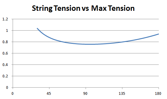
This is pretty close to constant string tension.
The whole print bed is covered without collisions. I have some slight modifications that should will make it a lot safer than the .5mm clearance I enjoy in the video.
Hopefully, this new sturdier Simpson will be less alive when it comes to calibration. If I can get away with it, I would like to avoid crazy calibration schemes.
Edited 1 time(s). Last edit at 07/16/2013 08:43AM by nicholas.seward.
This is pretty close to constant string tension.

The whole print bed is covered without collisions. I have some slight modifications that should will make it a lot safer than the .5mm clearance I enjoy in the video.
Hopefully, this new sturdier Simpson will be less alive when it comes to calibration. If I can get away with it, I would like to avoid crazy calibration schemes.
Edited 1 time(s). Last edit at 07/16/2013 08:43AM by nicholas.seward.
|
Re: Grounded Experimental Delta Printer July 17, 2013 03:21AM |
Registered: 12 years ago Posts: 539 |

|
Re: Grounded Experimental Delta Printer July 17, 2013 03:25AM |
Registered: 10 years ago Posts: 979 |
Everyone, we need to keep the name "Maggie" under wraps. I am going to make every effort to only refer to her as "Simpson" or "Simplified Simpson" until FOX gets back to me on how licensing would work on something like this. My guess is they wouldn't be interested in partnering with me but who knows.
|
Re: Grounded Experimental Delta Printer July 18, 2013 03:31AM |
Registered: 10 years ago Posts: 979 |
I am finalizing my supplier for the all important torsion spring. My beta run is going to cost me $3/spring. A production run is going to cost me $0.75/spring. McMaster-Carr wants $4+ for a less than ideal spring. Simple Simpson is going to cost nothing to make. "Wealth Without Money" or at least "Wealth With a Small Amount of Money".
Even at the grand total of $2.25 for all 3 springs, this is the high dollar vitamin. The bearings are less than $0.40/piece. The bolts are all less than $0.10/piece. I think I have actually crossed over to the point where the plastic mechanicals cost more than the metal mechanicals. I can't wait to put the official BOM together to see what this thing is going to cost for someone buying off the shelf parts.
Even at the grand total of $2.25 for all 3 springs, this is the high dollar vitamin. The bearings are less than $0.40/piece. The bolts are all less than $0.10/piece. I think I have actually crossed over to the point where the plastic mechanicals cost more than the metal mechanicals. I can't wait to put the official BOM together to see what this thing is going to cost for someone buying off the shelf parts.
|
Re: Grounded Experimental Delta Printer July 19, 2013 11:16AM |
Registered: 10 years ago Posts: 18 |
|
Re: Grounded Experimental Delta Printer July 19, 2013 11:44AM |
Registered: 10 years ago Posts: 979 |
You probably won't be able to snag one of the 20 beta machines but if you go to ConceptFORGE.org and give me your info I will put you in the queue for the production machines.
|
Re: Grounded Experimental Delta Printer July 20, 2013 01:57AM |
Registered: 10 years ago Posts: 979 |
If any of you have been dying to see physical progress then this next week will be worth watching. I have been away from my tools for 2+ weeks now and am about to go crazy. I have channeled that energy into virtual endeavors but at the end of the day we need a physical machine.
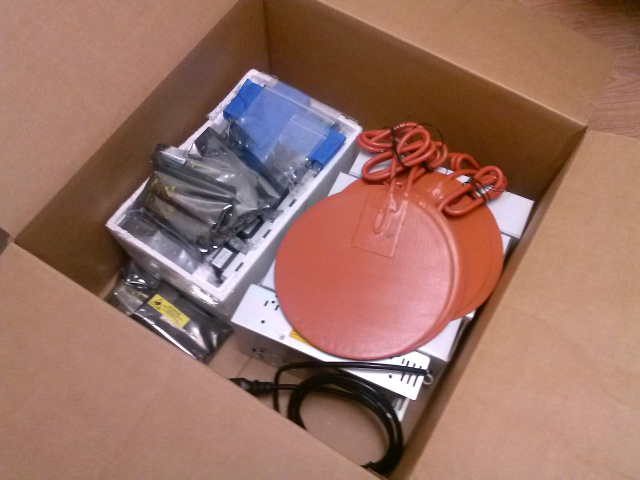
3D Printer Guts!
Today has been very exciting. My cousin that runs a cabinet shop just bought a 4'x8' CNC mill. He is going to mill some MDF for my machines and have a rugged plastic coating applied by a friend of his. I just ordered 2000 608 bearings moments ago. I received a partial order for the electronics earlier today. I am just about to order all the bolts. Exciting stuff. The most exciting thing is that I got my first donation for this project. Thank you Tim Deagan! If anyone else wants to give a donation before they run out, I put a link on the Thingiverse site. :-)
I mapped out this next week and it looks like I should be able to get Wally and SimpleSimpson to both make some first moves.
I have gotten an amazing amount of people interested in my beta kits. It is going to be hard to pick the 40 people to do the testing. I am going to do first come first served combined with how much they have participated in the project. It will not be easy but if all goes well, those that don't get beta kits will be first in line for the production run.
I am really looking forward to actually doing some physical building this week!
Edited 1 time(s). Last edit at 07/20/2013 01:59AM by nicholas.seward.
|
Re: Grounded Experimental Delta Printer July 24, 2013 01:39AM |
Registered: 10 years ago Posts: 979 |

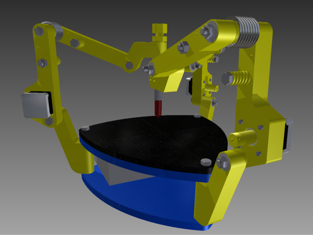
I am stuck in virtual land. I won't be getting my springs for a while. I moved back to a concentric mount. I am using 6702 bearings for the central hub. I tweaked a lot of the dimensions so I now can print everywhere in a 200mm diameter by 100mm tall cylinder. You can go much wider and much taller. The max height greater than 150mm. It is actually possible to position the tool beside the build platform. You can theoretically go anywhere on the build platform but it is advisable to stay away from the bolts since there is a singularity there.
I am going to try having the strings just slide over a M8 bolt. I also added a plastic string guide that surrounds the bolt. I think a mechanical advantage of 4-6 will be needed. The math says anything greater than 3 will work.
The most important thing I have done is change the color to yellow. :-)
Edited 1 time(s). Last edit at 07/24/2013 01:40AM by nicholas.seward.
|
Re: Grounded Experimental Delta Printer July 24, 2013 06:48AM |
Registered: 15 years ago Posts: 401 |
|
Re: Grounded Experimental Delta Printer July 26, 2013 06:33PM |
Registered: 10 years ago Posts: 145 |
Hello to everybody.
I'm new here and want to contribute to the community with my grain of salt.
I have to admit I was inspired by your design, Nicolas, I liked the idea of an "inverted" delta robot with a simple motor controlling the length of the arm (it is the final goal). So I put hands on work and ended with something very similar to your design, let's say a variation. I used a GT2 band to control both retraction and extension of the arm, so I used no springs on my design. I also approached the rotation of the base a little different, trying to mantain the offsets at 0 mm from the vertex of the triangle that models the system. Finally, I designed a way to mount the motor directly on the axis of rotation to minimize inertia, that I saw is/was one of your goals...oh, and I took your idea as a quick final modification to my design about not using screws to mount the motor.
Here are some images:
Feel free to incorporate anything on your design if you want.
Great job!
I'm new here and want to contribute to the community with my grain of salt.
I have to admit I was inspired by your design, Nicolas, I liked the idea of an "inverted" delta robot with a simple motor controlling the length of the arm (it is the final goal). So I put hands on work and ended with something very similar to your design, let's say a variation. I used a GT2 band to control both retraction and extension of the arm, so I used no springs on my design. I also approached the rotation of the base a little different, trying to mantain the offsets at 0 mm from the vertex of the triangle that models the system. Finally, I designed a way to mount the motor directly on the axis of rotation to minimize inertia, that I saw is/was one of your goals...oh, and I took your idea as a quick final modification to my design about not using screws to mount the motor.
Here are some images:


Feel free to incorporate anything on your design if you want.
Great job!
|
Re: Grounded Experimental Delta Printer July 26, 2013 07:23PM |
Registered: 10 years ago Posts: 145 |
This view is also important:
On the math side, as you know, the relationship between the lengt of the arm (the distance of the variable side of the triangle) and the angle we control is not linear, so, every turn of the motor changes the lenght at a different rate according to the angle at the moment, being 90 degres the "worst" case for resolution and the best for speed and 180 degrees being the opposite. How are you dealing with that? I'm using a final gearing of 3 to 1 that seems too low to overcome the loss of resolution at 90 degrees, where a 1.8 degree step changes the lenght more than 1mm!
Here is a graph (length change on the vertical axis and angle of the arm on horizontal axis):
What is your final pulley reduction? Is there any modification to the firmware to addres this issue? I also figured out the inverse kinematics of my model in MS Excel and learned that if I increase the gearing the resolution will be higher, but aproaching 180 and 0 the speed will be very very low. Do you plan to work your printer on certain restricted volume? I plan to add a 4th degree of freedom in the form of a variable height printing surface, so I can work the robot arms on an optimal angle.
I was dreaming, what if you could decouple the arms from the motors at the extended position and simultaneously coupling them to the base, so it can be lowered with no extra motors? I will probably start a new thread on that.
Keep the good work!

On the math side, as you know, the relationship between the lengt of the arm (the distance of the variable side of the triangle) and the angle we control is not linear, so, every turn of the motor changes the lenght at a different rate according to the angle at the moment, being 90 degres the "worst" case for resolution and the best for speed and 180 degrees being the opposite. How are you dealing with that? I'm using a final gearing of 3 to 1 that seems too low to overcome the loss of resolution at 90 degrees, where a 1.8 degree step changes the lenght more than 1mm!
Here is a graph (length change on the vertical axis and angle of the arm on horizontal axis):

What is your final pulley reduction? Is there any modification to the firmware to addres this issue? I also figured out the inverse kinematics of my model in MS Excel and learned that if I increase the gearing the resolution will be higher, but aproaching 180 and 0 the speed will be very very low. Do you plan to work your printer on certain restricted volume? I plan to add a 4th degree of freedom in the form of a variable height printing surface, so I can work the robot arms on an optimal angle.
I was dreaming, what if you could decouple the arms from the motors at the extended position and simultaneously coupling them to the base, so it can be lowered with no extra motors? I will probably start a new thread on that.
Keep the good work!
|
Re: Grounded Experimental Delta Printer July 26, 2013 07:33PM |
Registered: 10 years ago Posts: 979 |
That is great! It looks like you used my initial motor configuration from the first post on this forum.
Thoughts:
*How are you going to tighten up the motor joint. (You would need to tap the end of the drive shaft or terminate the drive pulley with plastic threads that extend through the bearing.)
*You need a larger polar moment of inertia for your arms to increase the torsional stability. Notice how all my arms are a solid 25x25mm square cross section now. You can play with weight reduction by changing the percent infill. (I think that is one of the biggest misconceptions about 3D printed parts. Physical volume doesn't equate directly to mass. In fact doing traditional truss like structures are much less effective than complex internal structures. I want to play with having the density of the inside increase as you move away from the center so you can get optimal torsional stability vs mass. Moral: design simple and let the computer reduce mass from the inside out.)
*The top pulley will need to be substantially bigger unless...something like this with two floating pulleys
*Pressfit bearings are a problem. I always use 2 bearings that are side loaded towards eachother. I also like to keep the mounting one sided to keep from worrying about tolerances so much.
*I wouldn't want to rely on a set screw to prevent lateral movement. It looks like the pictures show a clamp coupling which I think is needed.
*Abandoning the Annirak drive will cause the inverse kinematics to become more complex and you will have to reduce your top speed to get a mechanical advantage that can get 25 micron resolution everywhere you want to print.
Those are all just things to think about. I am behind your idea all together. I am also with you on statically mounting the steppers all together. However, every solution I come up with increases the complexity and simplicity is more important to me than acceleration or speed.
Thanks,
Nicholas Seward
Edited 1 time(s). Last edit at 07/26/2013 07:37PM by nicholas.seward.
|
Re: Grounded Experimental Delta Printer July 27, 2013 12:44PM |
Registered: 10 years ago Posts: 145 |
Thanks for the response Nicholas,
There are still some details I have to improve, as my design is not final yet. I think I will forget about the pulleys and will use gears instead. I think it is easier to increase the reduction with gears than with pulleys and bands. It will also reduce the vitamin count as they can be printed.
One thing I didin't fully understand is why going away from the Annirak drive will make more complex the equations. I see yours are very easy cause both arms are equal length and the offset from the base and the offset from the tool point is the same, so that reduces the complexity. On my idea the arms are different and there is only one offset from the tool point, that can be easily programed as an addition to the final point needed. Well, I thik I have to show you the numbers.
See you later.
|
Re: Grounded Experimental Delta Printer July 27, 2013 01:00PM |
Registered: 10 years ago Posts: 145 |
|
Re: Grounded Experimental Delta Printer July 27, 2013 01:12PM |
Registered: 10 years ago Posts: 979 |
|
Re: Grounded Experimental Delta Printer July 31, 2013 05:43AM |
Registered: 10 years ago Posts: 979 |
I asked prospective beta testers to fill out a form and I noticed a trend that many wanted to have more than one extruder. I am sorry to say that the beta machines will only have one extruder. That is for a lot of reason. Cost being the number 1 reason. The extra extruder is cheap and the extra filament drive is cheap. The controller board is not. There is also the matter that my target users and the beta testers are not quite the same people. All that said I thought you guys would like an idea of how you could accomplish multiple extruders. This idea limits the print area by a bit and makes the inverse kinematics much harder. If that isn't a deterent, you just have to print a few pieces and reconfigure your Simpson. Providing inverse kinematics for variants like these will be something that I will try to put in my software so that the end user can drastically modify Simpson but not have to be a math professor. (or a nerdy computer science teacher like me)
Edited 2 time(s). Last edit at 07/31/2013 05:57AM by nicholas.seward.
Edited 2 time(s). Last edit at 07/31/2013 05:57AM by nicholas.seward.
|
Re: Grounded Experimental Delta Printer August 05, 2013 06:56AM |
Registered: 11 years ago Posts: 29 |
|
Re: Grounded Experimental Delta Printer August 05, 2013 07:08AM |
Registered: 10 years ago Posts: 979 |
The only answer to the question "is the math going to be more complex?" is YYYYEEEEEEEEESSSSSSSSSS. However, it isn't going to be unmanageable in software. Double however, the offset for the extruders is changing all the time so the Slicing software will have to be hacked or there will have to be a tool change code and the firmware will have to take care of it. Triple however, firmware probably can't handle this.
Bottom line, it can be done and won't be too bad. You will have to put the inverse kinematics right into the slicing program for this to work with our present technology.
Note: this is all on the back burner. I have to focus on getting all the beta machines together and shipped and then I will get crazy again. Maybe, I will make a Six-arm Simpson or a Sextupteron.
|
Re: Grounded Experimental Delta Printer August 07, 2013 06:48PM |
Registered: 10 years ago Posts: 145 |
I finally decided on a new thread so not to deviate from the main development of Simpson. You can access it here:
New thread It is about my idea of a new arm. Thanks!
New thread It is about my idea of a new arm. Thanks!
|
Re: Grounded Experimental Delta Printer August 08, 2013 03:58AM |
Registered: 10 years ago Posts: 3 |
I have followed this thread from the start, and I think that if the firmware can't handle the math it would not be good for future development as adapting the slicer will be harder than the firmware.
I guess Having the same articulation on all the arms could make it simplier for multi extruders (and for one too)
I guess Having the same articulation on all the arms could make it simplier for multi extruders (and for one too)
|
Re: Grounded Experimental Delta Printer August 08, 2013 08:45AM |
Registered: 10 years ago Posts: 979 |
Currently I do a coordinate transformation after slicing but before printing. This technique can allow for any crazy math that you can cook up. Eventually as we incorporate a RaspberryPI-like computer with the printer it will be an invisible step.
Bottom line.... It is nice that the Annirak Drive is easy on the math but we shouldn't limit ourselves to stuff that can fit in firmware. Pick the best form and function. We have powerful computers to fix the math part.
Bottom line.... It is nice that the Annirak Drive is easy on the math but we shouldn't limit ourselves to stuff that can fit in firmware. Pick the best form and function. We have powerful computers to fix the math part.
|
Re: Grounded Experimental Delta Printer August 08, 2013 09:11AM |
Registered: 15 years ago Posts: 401 |


Sorry, only registered users may post in this forum.