Grounded Experimental Delta Printer
Posted by nicholas.seward
|
Re: Grounded Experimental Delta Printer October 21, 2013 09:48PM |
Registered: 12 years ago Posts: 5 |
|
Re: Grounded Experimental Delta Printer October 21, 2013 09:49PM |
Registered: 10 years ago Posts: 1,381 |
|
Re: Grounded Experimental Delta Printer October 21, 2013 10:17PM |
Registered: 12 years ago Posts: 5 |
A2 Wrote:
-------------------------------------------------------
> @MetalButcher
>
> Split/cut the .stl into two parts then glue them
> together.
> Add alignment notches/holes/pins.
Sorry, I've never tried to modify existing STL's A2, I just did a quick google search and I don't see an easy way to do that (without paying for Netfabb pro?), can you recommend a pointer/direction to go in?
edit: Apologies, looks like it's possible to do this in blender. I'll look into that.
Edited 1 time(s). Last edit at 10/21/2013 10:29PM by MetalButcher.
|
Re: Grounded Experimental Delta Printer October 21, 2013 10:43PM |
Registered: 10 years ago Posts: 1,381 |
I don't use .stl files, searched ("how do i modify a stl file") and found this:
FreeCAD can convert STL parts to solids.
[forums.reprap.org]
FreeCAD
[sourceforge.net]
[sourceforge.net]
[www.freecadweb.org]
and
In OpenSCAD you can import an STL file then manipulate that file with Boolean operations or movements.
With Blender you can import it then manipulate the vertices individually.
[groups.google.com]
and
SolidWorks
[grabcad.com]
and
Inventor
[forums.autodesk.com]
|
Re: Grounded Experimental Delta Printer October 26, 2013 05:12AM |
Registered: 10 years ago Posts: 1 |
|
Re: Grounded Experimental Delta Printer October 26, 2013 08:26AM |
Registered: 10 years ago Posts: 1,381 |

Good job!, and darn some one beat me to it

I know I'm not the first to have that idea, and I believe it was mentioned in the forum as well.
I'm curious if they solved the non linear issue 100% mechanically, with software, or is it still an open issue?
Edited 1 time(s). Last edit at 10/26/2013 08:27AM by A2.
|
Re: Grounded Experimental Delta Printer October 26, 2013 01:32PM |
Registered: 10 years ago Posts: 167 |
|
Re: Grounded Experimental Delta Printer October 26, 2013 01:42PM |
Registered: 10 years ago Posts: 1,381 |
Providing that the alignment of the worm screw is set properly, and there are no burrs,
and the worm wheel is printed with Nylon, it could last a life time of printing.
For an example, an automatic garage door uses a Nylon gear, that is about 3 inches in diameter,
and it lifts >100 lbs doors for many years.
and the worm wheel is printed with Nylon, it could last a life time of printing.
For an example, an automatic garage door uses a Nylon gear, that is about 3 inches in diameter,
and it lifts >100 lbs doors for many years.
|
Re: Grounded Experimental Delta Printer October 27, 2013 11:50PM |
Registered: 10 years ago Posts: 979 |
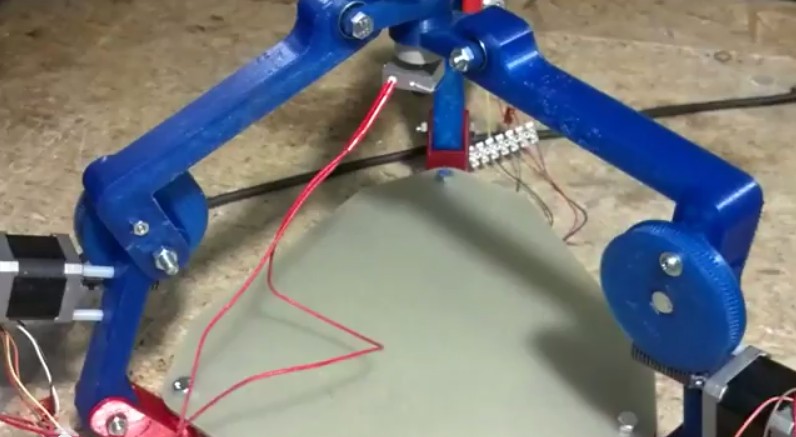
I figured I should officially weigh in on the GDR. First, I was so giddy to have someone make a derivative work. This machine is arguably simpler and more robust that GUS. I can't wait to see it print.
I suspect that the wheel will last for a very long time (years of constant printing) even if they are of PLA or ABS.
The GDR has no chance at being as fast as GUS but it is more precise. I suspect that there is some backlash from the worm drive but the combination of moving slow and gravity should keep the play from being an issue. If you wanted to push the speed then you just need a light torsion spring or something like it to keep the wheel always loaded in the same direction.
The GDR setup is also nonlinear so it will require an inverse trig function per axis per move. I really think this is a nonissue (math is cheap) but I thought it should be mentioned.
GUS's arms are substantially over-engineered but from my early experiments I discovered that the torsional stability is very important. For the biggest polar moment of inertia of a given amount of material, a hollow circular cross section is best. A solid square cross section is what I use because it is more printable and I am not in plastic reduction mode yet. I am curious if the GDR's thinner rectangular cross sections have enough torsional stability. My gut tells me that the GDR is on the good side of the line.
Bottomline: I am really impressed by the GDR. It is simple and slick. I hope others follow and make their own derivatives.
|
Re: Grounded Experimental Delta Printer October 28, 2013 06:41AM |
Registered: 10 years ago Posts: 1,381 |

Is the dog leg only for build envelope clearance?
Would coming off the center line of rotation further simply the math,
or even solve the nonlinear problem, or partially solve it?
What material is the build table made of?
A2
Edited 2 time(s). Last edit at 10/28/2013 06:44AM by A2.
|
Re: Grounded Experimental Delta Printer October 28, 2013 06:47AM |
Registered: 10 years ago Posts: 18 |
|
Re: Grounded Experimental Delta Printer October 28, 2013 01:28PM |
Registered: 10 years ago Posts: 56 |
Sweet! That’s my bot. I will try to answer everyone’s questions.
Worm Gears:
The worm gears are printed in PLA for now, possibly nylon later. I am pleased with the lifespan of them so far. Even after slipping the worm several times from driving too far in the wrong direction, I haven’t seen any damage. I think lube will be important.
Build Table:
The main structure is corian with a sheet of FR4 fiberglass on top. A little hairspray and pla and abs stick to the FR4 nicely.
Dogleg:
It was for clearance. I just take the hypotenuse as the length of the segment.
I am still working on getting the inverse trig calculations implemented in the marlin firmware. I will post an update when I make some progress.
|
Re: Grounded Experimental Delta Printer October 28, 2013 05:24PM |
Registered: 10 years ago Posts: 145 |
|
Re: Grounded Experimental Delta Printer November 05, 2013 10:25AM |
Registered: 10 years ago Posts: 56 |
I believe I have most of the kinks worked out of the firmware. Right now I am working on getting all of the movment calibrated. Appears to be decent challenge.
Here are a few test videos:
http://www.youtube.com/watch?v=C_L6mChi0hc
http://www.youtube.com/watch?v=ZdIECk7XLHw
and some code:
If anyone sees something I missed, let me know
Jon @ Solidus Labs
Edited 1 time(s). Last edit at 11/05/2013 11:04AM by Solidus Labs.
Here are a few test videos:
http://www.youtube.com/watch?v=C_L6mChi0hc
http://www.youtube.com/watch?v=ZdIECk7XLHw
and some code:
double La_1;
double La_2;
double La_3;
double Da_1;
double Da_2;
double Da_3;
double Ra_1;
double Ra_2;
double Ra_3;

Ra_1=sqrt(sq(cartesian[X_AXIS]-V1_X)+ sq(cartesian[Y_AXIS]-V1_Y));
Ra_2=sqrt(sq(cartesian[X_AXIS]-V2_X)+ sq(cartesian[Y_AXIS]-V2_Y));
Ra_3=sqrt(sq(cartesian[X_AXIS]-V3_X)+ sq(cartesian[Y_AXIS]-V3_Y));

La_1=sq(Ra_1-Nx+Sx)+sq(cartesian[Z_AXIS]-Sv+Nv1);
La_2=sq(Ra_2-Nx+Sx)+sq(cartesian[Z_AXIS]-Sv+Nv2);
La_3=sq(Ra_3-Nx+Sx)+sq(cartesian[Z_AXIS]-Sv+Nv3);

Da_1=((sqL1L2-La_1)/theta_CEND);
Da_2=((sqL1L2-La_2)/theta_CEND);
Da_3=((sqL1L2-La_3)/theta_CEND);

if (Da_1 <-1 || Da_1 > 1)
{
    Da_1=floor(Da_1);
    SERIAL_ECHOPGM("Arm Limit X\n");
}
if (Da_2 <-1 || Da_2 > 1)
{
    Da_2=floor(Da_2);
    SERIAL_ECHOPGM("Arm Limit Y\n");
}
if (Da_3 <-1 || Da_3 > 1)
{
    Da_3=floor(Da_3);
    SERIAL_ECHOPGM("Arm Limit Z\n");
}
delta[X_AXIS]= acos(Da_1)*rad2ang;
delta[Y_AXIS]= acos(Da_2)*rad2ang;
delta[Z_AXIS]= acos(Da_3)*rad2ang;
If anyone sees something I missed, let me know
Jon @ Solidus Labs
Edited 1 time(s). Last edit at 11/05/2013 11:04AM by Solidus Labs.
|
Re: Grounded Experimental Delta Printer November 05, 2013 11:07AM |
Registered: 10 years ago Posts: 1,381 |
Yoo-hoo!
Looking forward to your validation print!
Please add notes to your code so I can learn from your work!
Tks!
A2
Edited 1 time(s). Last edit at 11/05/2013 11:08AM by A2.
Looking forward to your validation print!
Please add notes to your code so I can learn from your work!
Tks!
A2
Quote
Solidus Labs
I believe I have most of the kinks worked out of the firmware. Right now I am working on getting all of the movment calibrated. Appears to be decent challenge.
Here are a few test videos:
http://www.youtube.com/watch?v=_qVeYwdC59g
http://www.youtube.com/watch?v=ZdIECk7XLHw
and some code:
double La_1;
double La_2;
double La_3;
double Da_1;
double Da_2;
double Da_3;
double Ra_1;
double Ra_2;
double Ra_3;

Ra_1=sqrt(sq(cartesian[X_AXIS]-V1_X)+ sq(cartesian[Y_AXIS]-V1_Y));
Ra_2=sqrt(sq(cartesian[X_AXIS]-V2_X)+ sq(cartesian[Y_AXIS]-V2_Y));
Ra_3=sqrt(sq(cartesian[X_AXIS]-V3_X)+ sq(cartesian[Y_AXIS]-V3_Y));

La_1=sq(Ra_1-Nx+Sx)+sq(cartesian[Z_AXIS]-Sv+Nv1);
La_2=sq(Ra_2-Nx+Sx)+sq(cartesian[Z_AXIS]-Sv+Nv2);
La_3=sq(Ra_3-Nx+Sx)+sq(cartesian[Z_AXIS]-Sv+Nv3);

Da_1=((sqL1L2-La_1)/theta_CEND);
Da_2=((sqL1L2-La_2)/theta_CEND);
Da_3=((sqL1L2-La_3)/theta_CEND);

if (Da_1 <-1 || Da_1 > 1)
{
    Da_1=floor(Da_1);
    SERIAL_ECHOPGM("Arm Limit X\n");
}
if (Da_2 <-1 || Da_2 > 1)
{
    Da_2=floor(Da_2);
    SERIAL_ECHOPGM("Arm Limit Y\n");
}
if (Da_3 <-1 || Da_3 > 1)
{
    Da_3=floor(Da_3);
    SERIAL_ECHOPGM("Arm Limit Z\n");
}
delta[X_AXIS]= acos(Da_1)*rad2ang;
delta[Y_AXIS]= acos(Da_2)*rad2ang;
delta[Z_AXIS]= acos(Da_3)*rad2ang;
If anyone sees something I missed, let me know
Jon @ Solidus Labs
Edited 1 time(s). Last edit at 11/05/2013 11:08AM by A2.
|
Re: Grounded Experimental Delta Printer November 05, 2013 01:17PM |
Registered: 10 years ago Posts: 26 |
Re: GDR (the worm gear drive version) designed by Jon @ Solidus Labs.
That looks good! Couple of comments / questions:
1. Do you think it will move as fast as the GED? Or is the worm gear limited in speed in comparison? If it is slower, what is the advantage?
2. Where do you get the metal worm drive gear? That part is /not/ 3d printed, correct? What does it cost?
[www.linistepper.com] Open source stepper motor drivers.
|
Re: Grounded Experimental Delta Printer November 05, 2013 01:27PM |
Registered: 10 years ago Posts: 26 |
Quote
nicholas.seward
... I have yet to release the gear arm version. Should be within the month.
Just so you know (like there could be any confusion! LOL) I'm really looking forward to trying to print one of these. It's actually sort of tied in to my own little project for a "SkyCam" robot in that they are both using cables instead of the more traditional gears or belts:
[www.thingiverse.com]
I really think the idea of "block and tackle" or other uses of "cables" with stepper motors is interesting. Very low mass, very fast, very cheap.
[www.linistepper.com] Open source stepper motor drivers.
|
Re: Grounded Experimental Delta Printer November 05, 2013 01:35PM |
Registered: 10 years ago Posts: 979 |
@JamesNewton: For reference GUS can move in excess of 1000mm/s for a long straight-line move. However, I wouldn't even dream of printing any faster than around 200mm/s. Jon will have to chime in on the speed of the GDR. I would imagine that his top speed is much much lower but as long as you can reach 60mm/s then you can be a Mendel replacement. I think the advantage here is that it is easier to build, and easier to maintain. The GDR also has higher resolution but I doubt that will be noticeable by most users. Great job Jon!
|
Re: Grounded Experimental Delta Printer November 05, 2013 02:06PM |
Registered: 10 years ago Posts: 100 |
@Jon - Nice looking setup in the video. Very clean!
Watching it brought up some questions in my mind:
I was wondering if you considered mounting the motors lower on the arm and pointed up to reduce the moving inertia?
That might also make it easier to put in a smaller gear for a lower ratio and faster moves.
Have you considered a counterweight extending outside on the top arm?
A fairly linear force spring could also be used. I could not tell if you already had a spring counterbalance.
That would reduce the load on the worm gear to practically nothing. You might want to have a little loading for anti-backlash.
|
Re: Grounded Experimental Delta Printer November 06, 2013 09:58AM |
Registered: 10 years ago Posts: 56 |
Quote
JamesNewton
Re: GDR (the worm gear drive version) designed by Jon @ Solidus Labs.
That looks good! Couple of comments / questions:
1. Do you think it will move as fast as the GED? Or is the worm gear limited in speed in comparison? If it is slower, what is the advantage?
2. Where do you get the metal worm drive gear? That part is /not/ 3d printed, correct? What does it cost?
1. I agree with Nicholas, it will not be as fast as GED but I have tested fast movemnts up to 300mm/s. I am not using a proper power supply so i expect the performance to increase.
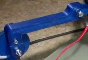
2. The worm wheel is 3d printer but the worm is just 1/2-10 lead screw. I usually get stock at about 10-20$ per meter.
Quote
see3d
Watching it brought up some questions in my mind:
I was wondering if you considered mounting the motors lower on the arm and pointed up to reduce the moving inertia?
That might also make it easier to put in a smaller gear for a lower ratio and faster moves.
I did consider moving the motors to the bottom joint but that would restrict your z height, the upper arms could never go above parallel to the print surface.
I think a spring would be a better idea than a counterweight to keep the inertia down. The weight of the print head should keep the worm gear nicely loaded but maybe adding a light spring could counteract some high inertia movements.Quote
see3d
Have you considered a counterweight extending outside on the top arm?
A fairly linear force spring could also be used. I could not tell if you already had a spring counterbalance.
That would reduce the load on the worm gear to practically nothing. You might want to have a little loading for anti-backlash.
|
Re: Grounded Experimental Delta Printer November 06, 2013 11:44AM |
Registered: 10 years ago Posts: 100 |
Quote
Solidus Labs
Quote
see3d
Watching it brought up some questions in my mind:
I was wondering if you considered mounting the motors lower on the arm and pointed up to reduce the moving inertia?
That might also make it easier to put in a smaller gear for a lower ratio and faster moves.
I did consider moving the motors to the bottom joint but that would restrict your z height, the upper arms could never go above parallel to the print surface.
I guess we are not on the same page here. How does rotating the motor 90 degrees clockwise restrict the Z?

|
Re: Grounded Experimental Delta Printer November 06, 2013 12:47PM |
Registered: 10 years ago Posts: 56 |
Quote
see3d
Quote
Solidus Labs
I guess we are not on the same page here. How does rotating the motor 90 degrees clockwise restrict the Z?
Sorry, it must have been too early when I misread your question. I see what you are saying now. The only reason I have the motor in its current position is because it was easy to mount. I agree, I think if you were trying to reduce the inertia and improve the speeds, you would want to shrink the worm gear and rotate the motor to make it closer to the arm. Otherwise since the motor is almost square, rotating the motor would put the motor in almost the same spot and shrinking the worm gear would move the motor up higher on the arm making inertia worse.
|
Re: Grounded Experimental Delta Printer November 06, 2013 02:00PM |
Registered: 10 years ago Posts: 26 |
Quote
Solidus Labs
2. The worm wheel is 3d printer but the worm is just 1/2-10 lead screw. I usually get stock at about 10-20$ per meter.
So the lead screw is attached to the motor shaft with a coupler? Thats... pretty cool! And 300mm/s is more than fast enough. Pretty darn neat.
Edited 1 time(s). Last edit at 11/06/2013 02:02PM by JamesNewton.
[www.linistepper.com] Open source stepper motor drivers.
|
Re: Grounded Experimental Delta Printer November 06, 2013 09:22PM |
Registered: 10 years ago Posts: 56 |
|
Re: Grounded Experimental Delta Printer November 06, 2013 10:35PM |
Registered: 10 years ago Posts: 1,381 |
|
Re: Grounded Experimental Delta Printer November 07, 2013 06:05PM |
Registered: 15 years ago Posts: 401 |
|
Re: Grounded Experimental Delta Printer November 07, 2013 06:31PM |
Registered: 10 years ago Posts: 1,381 |
|
Re: Grounded Experimental Delta Printer November 07, 2013 06:38PM |
Registered: 10 years ago Posts: 979 |
@A2: I think we are getting our terminology mixed up a bit. The worm drive results in a non-linear graph of stepper rotation vs actuated distance. (The non-linear response from this worm drive setup is inherent.) What (I think) Annirak is saying is the non-linearity problem that GUS kinda (I have some solutions if I just had time to test them.) has right now is from the string routing and this doesn't apply to the GDR? So what he is say is that the GDR code can't fix the non-linearity from the string routing.
|
Re: Grounded Experimental Delta Printer November 07, 2013 06:45PM |
Registered: 10 years ago Posts: 1,381 |
|
Re: Grounded Experimental Delta Printer November 08, 2013 04:15AM |
Registered: 15 years ago Posts: 401 |


Sorry, only registered users may post in this forum.