|
Re: Grounded Experimental Delta Printer September 05, 2013 03:03AM |
Registered: 15 years ago Posts: 401 |
I thought I doodled the inverse kinematics up at the start of this thread.
[forums.reprap.org]
They need a little updating for the new design.
Nicholas.Seward used essentially the same math, but with some simplifications. I don't think that some of those simplifications still apply (e.g. shoulder joints are no longer cosited in the x-y plane.
This is where it gets different from the previous kinematics I posted. That length is actually the control variable. Let's call the inside-length of arm A LIa, and the outside length of arm A LOa.
We already know that LIa + LOa is constant, so we'll just control LIa, since it is proportional to la, derived above.
So, finally, the control variables are:
LIa = fc(la-gc)/sc
LIb = fc(lb-gc)/sc
LIc = fc(lc-gc)/sc
where:
sc is the proportionality constant between the movement of the arms and the string
gc is the constant separation between the centres of the gears.
fc is the force multiplication constant of the block & tackle arrangement
That should do it.
An important note: If this isn't already obvious, the torque division between the threads and the arm ends should be a power of two in order to simplify the math. Similarly, that requirement can be removed by making them an integral multiple of the length and using an equivalent block & tackle force multiplier.
To be perfectly clear, if dt is the distance between the gear centre and a thread and da is the distance between the gear centre and the arm end, then da/dt should be an integer. This is even better if da/dt is a power of 2.
[forums.reprap.org]
They need a little updating for the new design.
Nicholas.Seward used essentially the same math, but with some simplifications. I don't think that some of those simplifications still apply (e.g. shoulder joints are no longer cosited in the x-y plane.
Quote
Annirak
You have three input variables: the three angles of the elbow joints, Aa, Ab, Ac. You have three outputs: x,y,z. We need to go the opposite direction.
There are ten givens.
The three base vectors. These are the offsets between the origin and the centre of the horizontal shoulder joint.
Ba =
Bb =
Bc =
The horizontal offset between the horizontal shoulder joint and the vertical shoulder joint; positive if the vertical joint is more central than the horizontal one, negative otherwise.
sx
The length between the nozzle's central axis and the attachment point of the arm.
nx
The height of each arm's nozzle bearing above the nozzle.
nva,nvb,nvc
The scalar lengths of the two arm segments
l1, l2
Note that I am assuming that Ba,Bb,Bc are at the centre of the horizontal shoulder joint's axis, but at the height of the vertical shoulder joint's axis. With that out of the way, here's the math:
Let P be the position vector of the nozzle. P =
Let Ha,Hb,Hc be the vector between each Bx and the nozzle.
Ha = P-Ba
Hb = P-Bb
Hc = P-Bc
(9 subtractions)
Let ra,rb,rc be the cylindrical, radial distance from each, respective shoulder joint's horizontal axis to the nozzle
ra = sqrt(Ha_x^2 + Ha_y^2)
rb = sqrt(Hb_x^2 + Hb_y^2)
rc = sqrt(Hc_x^2 + Hc_y^2)
(6 multiply, 3 add, 3 sqrt)
Where Ha_x is the x-component of Ha, Ha_y is the y-component of Ha, etc.
Let la,lb,lc be the length of each, respective arm from the vertical shoulder to the wrist joint.
la = sqrt( (ra-sx-nx)^2 + (Ha_z + nva)^2 )
lb = sqrt( (rb-sx-nx)^2 + (Hb_z + nvb)^2 )
lc = sqrt( (rc-sx-nx)^2 + (Hc_z + nvc)^2 )
(6 multiply, 6 add, 3 subtract)
This is where it gets different from the previous kinematics I posted. That length is actually the control variable. Let's call the inside-length of arm A LIa, and the outside length of arm A LOa.
We already know that LIa + LOa is constant, so we'll just control LIa, since it is proportional to la, derived above.
So, finally, the control variables are:
LIa = fc(la-gc)/sc
LIb = fc(lb-gc)/sc
LIc = fc(lc-gc)/sc
where:
sc is the proportionality constant between the movement of the arms and the string
gc is the constant separation between the centres of the gears.
fc is the force multiplication constant of the block & tackle arrangement
That should do it.
An important note: If this isn't already obvious, the torque division between the threads and the arm ends should be a power of two in order to simplify the math. Similarly, that requirement can be removed by making them an integral multiple of the length and using an equivalent block & tackle force multiplier.
To be perfectly clear, if dt is the distance between the gear centre and a thread and da is the distance between the gear centre and the arm end, then da/dt should be an integer. This is even better if da/dt is a power of 2.
|
Re: Grounded Experimental Delta Printer September 05, 2013 04:01AM |
Registered: 10 years ago Posts: 979 |
A few notes:
I like simplicity so I have done a few things in my design to simplify the math. What Annirak has written above will cover any generic Simpson with a concentric extruder. (Off axis extruders aren't that bad but let's not confuse the issue.)
For the current iteration...
The distance from the shoulder axis to the humorous connection is equal to the distance from the extruder axis to the forearm connection.
sx=-nx
All the forearms connect at the same plane
nva=nvb=nvc=nv
You can pretend that the shoulders are lower by the z distance from the tip of the nozzle to the forearm connection plane.
Ba_z'=Ba_z-nv
Bb_z'=Bb_z-nv
Bc_z'=Bc_z-nv
Ha' = P-Ba'
Hb' = P-Bb'
Hc' = P-Bc'
That leaves you with...
la = len(Ha')= sqrt( (Ha_x')^2 + (Ha_y')^2 + (Ha_z')^2)
lb = len(Hb')= sqrt( (Hb_x')^2 + (Hb_y')^2 + (Hb_z')^2)
lc = len(Hc')= sqrt( (Hc_x')^2 + (Hc_y')^2 + (Hc_z')^2)
Given that Ba', Bb', and Bc' are all constants I get a total of 15 add, 9 multiply, and 3 sqrt. That is a bit of an improvement.
The Annirak Drive or the Proportional Gear Joint Drive both make the relative rotation of one of the steppers proportional to la, lb, or lc.
My plan is for all of this to be programmatically solved for after calibration. Calibration will consist of pushing a few buttons on the screen to get the nozzle to a position indicated by a picture on the screen. (But if you can't wait, the math is above and I have a rough gcode preprocessor on thingiverse.)
Not that you can't fit this in firmware but I personally do all the inverse kinematics with a gcode preprocessor. The reason for this is that is I am already planning a monolithic software program for Simpson and Wally. (Calibrate, run, slice, etc all from one program.) This program will make the gcode preprocessing invisible to a user and it will make it easy for me to adapt to crazy new designs that I have. The firmware that I use is vanilla Repetier. This also has the benefit letting Simpson and Wally share the same firmware. (One downside is that the calibration data is stored on the host. However, one could modify the firmware to store calibration data or you could put it on a flash drive. I imagine that most people don't typically move a 3D printer from computer to computer.)
|
Re: Grounded Experimental Delta Printer September 05, 2013 02:39PM |
Registered: 12 years ago Posts: 85 |
|
Re: Grounded Experimental Delta Printer September 06, 2013 03:43AM |
Registered: 15 years ago Posts: 401 |
I'm being pedantic.
La = gc + lw * ka / kp
where
La is the total arm length,
gc is the constant distance between gear centres,
lw is the length of wire that the stepper moves
ka is the mechanical disadvantage of the arm (these arms are third-class levers)
kp is the aggregate mechanical advantage of the pulleys
The real difference here is gc.
Not quite. I mean, it's close enough to make little difference, but I think it's an important distinction. The PGJD has an additional term:Quote
nicholas.seward
The Annirak Drive or the Proportional Gear Joint Drive both make the relative rotation of one of the steppers proportional to la, lb, or lc.
La = gc + lw * ka / kp
where
La is the total arm length,
gc is the constant distance between gear centres,
lw is the length of wire that the stepper moves
ka is the mechanical disadvantage of the arm (these arms are third-class levers)
kp is the aggregate mechanical advantage of the pulleys
The real difference here is gc.
|
Re: Grounded Experimental Delta Printer September 06, 2013 07:15PM |
Registered: 10 years ago Posts: 23 |
nicholas.seward Wrote:
I don't know programing, but there's a thing called Parallella that look interesting :
[www.parallella.org]
Edited 1 time(s). Last edit at 09/06/2013 07:17PM by Buytaert.
Quote
General engineering wisdom is to use one or more of the following techniques.
*Increase mass: This lowers the natural frequencies and reduces the amplitude of vibrations.
*Increase damping: This can remove vibrational modes altogether and will reduce the amplitude of those remaining.
*Passively Isolate: This is really just a specialized form of increasing mass and adding damping.
*Actively Isolate: As far as I know, no one has come up with a cost effective way to use an active control system to mitigate vibrations in a production machine. However, this has the potential to allowing a light, low friction machine to do unusual things like mill metal. However, however, the processing power needed to run a system like this would be outrageous along with the fact that reaction time needs to be a fraction of the period of the oscillation that you are mitigating. Assuming the hardware existed, the software would still have to be written. Hopefully, this will be an option someday.
As you can imagine that using any of the first three ways will reduce speed and/or increase motion control costs.
I don't know programing, but there's a thing called Parallella that look interesting :
[www.parallella.org]
Edited 1 time(s). Last edit at 09/06/2013 07:17PM by Buytaert.
|
Re: Grounded Experimental Delta Printer September 07, 2013 03:41AM |
Registered: 12 years ago Posts: 85 |
|
Re: Grounded Experimental Delta Printer September 07, 2013 08:11AM |
Registered: 15 years ago Posts: 401 |
I have a couple of those ordered. They certainly have the processing power, but the other part of the question is whether they can handle the latency. How fast do you have to respond, and is that even possible?Quote
Buytaert
I don't know programing, but there's a thing called Parallella that look interesting :
[www.parallella.org]
|
Re: Grounded Experimental Delta Printer September 07, 2013 01:41PM |
Registered: 12 years ago Posts: 85 |
If we are talking about responding to oscillation, I think the better first focus is on milling techniques that minimize it?
The negative of a lightweight head for milling is high oscillation potential. The positive is high speed. Perhaps using that high speed, you can mill in a pattern that reduces oscillation as a filter for the incoming/upcoming path. Then your counterweight algorithm starts by responding to a smoothed version of the inverse(?) state of the oscillation minimization algorithm, but X steps ahead within the filtered path due to its heavier weight/slower movement. Attach an accelerometer to the head, the counterweight and perhaps the bed and use the differentials to weight the positioning queues of the counterweight algorithm or to add real-time feedback as 'jitter' to the smoothed counterweight algorithm. After adjustments are applied, the jitter algorithm measures telemetry again to 'score' the results of its last move, use that to apply weights, and recalculate the base algorithm applied to the upcoming buffer.
I see every direct movement from point A to B as a frame, where a new frame is triggered by the head changing directions. Buffer N frames ahead, move the counterweight first, move head, apply jitter within the frame for active correction, and constantly recalculate the 'base' of the next few upcoming frames according to the jitter and feedback from the jitter.
head: buffered gcode (X steps behind real-time)
apply inverse of jitter smoothing filter to the upcoming buffer, re-apply to weight the full upcoming buffer
move
repeat
counterbalance: inverse gcode for N steps ahead of the head (more 'realtime' than the head but still buffered)
apply smoothing filter to upcoming N steps
measure/update jitter weights
apply jitter weighting
move
measure/update jitter weights
repeat
Look for trigger events in the upcoming gcode stream and apply markers that also weight or reset scoring in the algorithms:
- sudden direction changes
- lifting and moving X distance
I think you are 'successful' when you can align the frames of the gcode of the head/counterbalance, and graph the difference/offset to the original gcode over time for the same frames. On a waveform, the offsets should resemble the oscillations your machine/movement produces. If we can get this far, we have a platform that someone can work with and be inspired to experiment with different scoring and pathing algorithms on.
Could this be done with just two RAMPS-style boards and an Android/Pi feedback controller that managed the gcode buffer algorithm and fed the RAMPS?
Edited 1 time(s). Last edit at 09/07/2013 01:54PM by jason.fisher.
|
Re: Grounded Experimental Delta Printer September 11, 2013 07:15AM |
Registered: 10 years ago Posts: 979 |
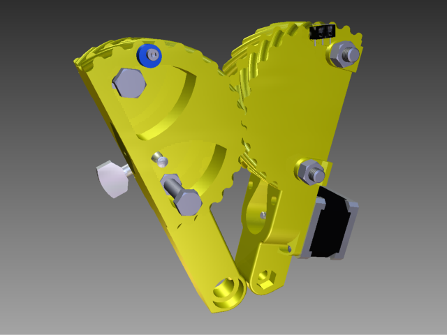
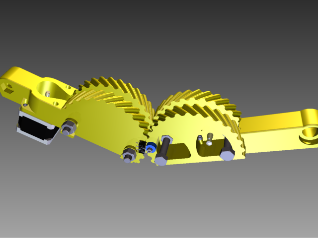
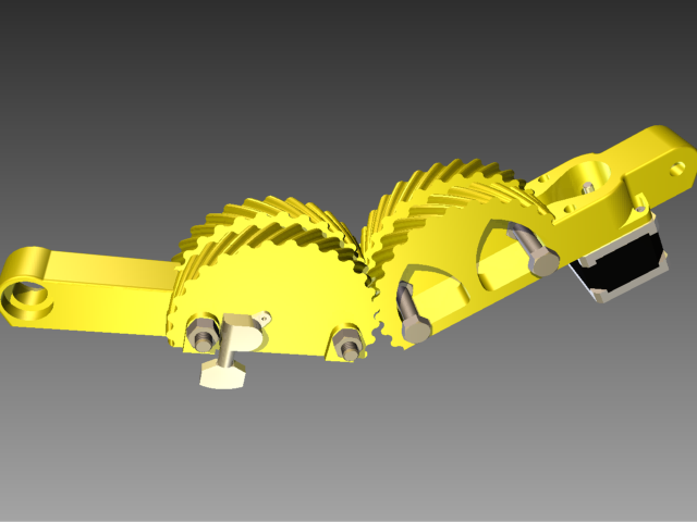
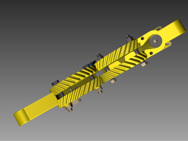
Here are the new arms. I will be printing them today.
I am super happy with the design. They don't look like igloos or boats (much) and I got my extra gear width (40mm from side to side) and my finger access. There is a place to hook the spring, insert the tuning peg, mount the limit switch, and mount a eccentric stop for limit switch adjustment. They are very printable. Any teeth (near the bottom) that could (unlikely) get messed up will never be engaged. Let me know if you guys see anything obvious that I missed.
Edited 1 time(s). Last edit at 09/11/2013 07:16AM by nicholas.seward.
I am super happy with the design. They don't look like igloos or boats (much) and I got my extra gear width (40mm from side to side) and my finger access. There is a place to hook the spring, insert the tuning peg, mount the limit switch, and mount a eccentric stop for limit switch adjustment. They are very printable. Any teeth (near the bottom) that could (unlikely) get messed up will never be engaged. Let me know if you guys see anything obvious that I missed.


Edited 1 time(s). Last edit at 09/11/2013 07:16AM by nicholas.seward.
|
Re: Grounded Experimental Delta Printer September 11, 2013 08:17AM |
Registered: 15 years ago Posts: 401 |
There's one thing that's been bugging me since the start of the gear-based design. I'm not sure we can fix it without breaking the simplicity of the math.
The two pairs of mounts have an asymmetric range of motion. The outer bolts get much closer together than the inner bolts. The inner bolts get much further apart than the outer bolts. Unless my physics are horrendously wrong, what this works out to, in practice, is that you can exert much more torque near the closed position of the arm than you can at the open position.
What I would suggest is rotating the bolts so that they are spaced equally at 90deg. It will give a much more consistent torque curve. This will put the two sets of pulley bolts at a 45 degree angle from the arm's baseline. It might take a bit of a redesign to accomodate the outer bolt, which will need to be mounted in what is now empty space.
I'll have to do the math (I'll take a crack at that when I'm off work in a few hours), but I think it may be more complex. Of course, a second look at it may reveal that the math is identical. We shall see.
|
Re: Grounded Experimental Delta Printer September 11, 2013 12:39PM |
Registered: 11 years ago Posts: 10 |
|
Re: Grounded Experimental Delta Printer September 11, 2013 01:04PM |
Registered: 10 years ago Posts: 18 |
|
Re: Grounded Experimental Delta Printer September 11, 2013 01:11PM |
Registered: 11 years ago Posts: 10 |
|
Re: Grounded Experimental Delta Printer September 11, 2013 01:47PM |
Registered: 10 years ago Posts: 979 |
@Annirak: So with a Wally-like arm drive you get near constant driving torque. With a PGDJ (Proportional Gear Drive Joint) you get a constant driving force on a line of action through the arm ends.
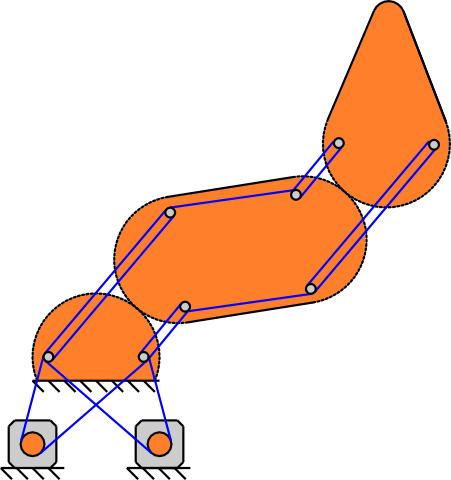
Breaking the proportionality of a GDJ (Gear Drive Joint) could be advantageous. This is my basic idea for a one arm SCARA. The steppers would be stationary and would drive the arm in a way that is roughly analogous to a hbot. (Don't pay attention to my string placement. I just slapped some lines on the diagram to give context.)
@bluscape: I think I am out of beta test slots for Wally and Simpson. However, I haven't asked for money yet so I am bound to have a few openings in the near future. Give me your email at http://conceptforge.org/. All offers for beta slots go through that mailing list. (A Kickstarter is roughly scheduled for mid-December.)
Edited 1 time(s). Last edit at 09/11/2013 01:47PM by nicholas.seward.
Breaking the proportionality of a GDJ (Gear Drive Joint) could be advantageous. This is my basic idea for a one arm SCARA. The steppers would be stationary and would drive the arm in a way that is roughly analogous to a hbot. (Don't pay attention to my string placement. I just slapped some lines on the diagram to give context.)

@bluscape: I think I am out of beta test slots for Wally and Simpson. However, I haven't asked for money yet so I am bound to have a few openings in the near future. Give me your email at http://conceptforge.org/. All offers for beta slots go through that mailing list. (A Kickstarter is roughly scheduled for mid-December.)
Edited 1 time(s). Last edit at 09/11/2013 01:47PM by nicholas.seward.
|
Re: Grounded Experimental Delta Printer September 11, 2013 02:00PM |
Registered: 10 years ago Posts: 145 |
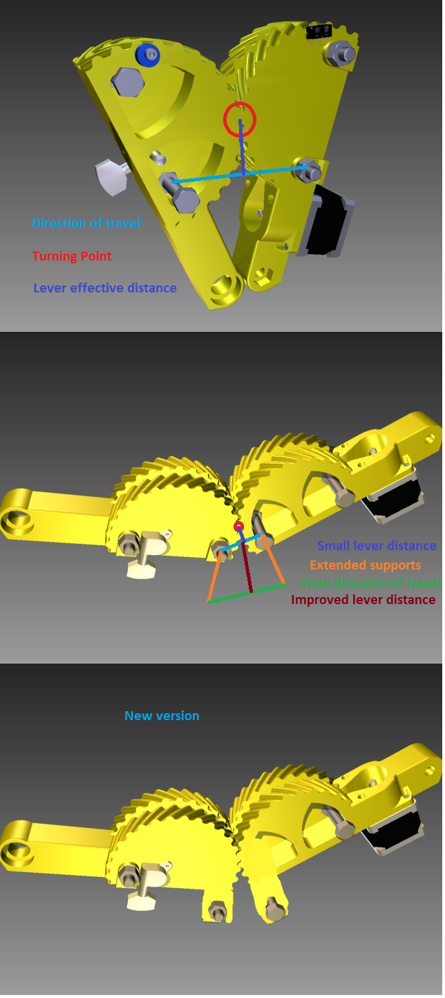
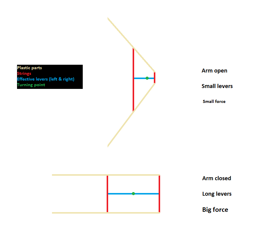
They way the arm is structured make increasingly difficult to turn the arm out of position, I mean, the force needed increases as you try to overcome the motor force because, by design, (intended or not) the distance of the effective lever increases as you try to close the arm.
Besides that, even when the force may not be the best attainable, It may still be more than enough.

No, I'm wrong.
The symmetry of the design make it work ok, as the length of the string is constant. If the outer bolts are placed in another position as drawn, they will separate more quickly than the inner bolts can get closer, inducing slack to the string.
The issue here is that, by the "disposable knife design" the inner bolts cannot get closer, due to the extended mounting points, while inthe other hand, the outer bolts can get very close as there are no extensions on their side.
So, if anyone would like to increase the torque, the mounting point of both bolts shoul be moved symmetrically, to maintain a constant length of string.
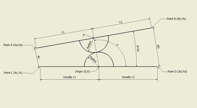
Please see this diagram:

L1 and L2 have to be equal so AC and BD add to a constant number.
|
Re: Grounded Experimental Delta Printer September 11, 2013 02:06PM |
Registered: 10 years ago Posts: 145 |
nicholas.seward Wrote:
-------------------------------------------------------
> @Annirak: So with a Wally-like arm drive you get
> near constant driving torque. With a PGDJ
> (Proportional Gear Drive Joint) you get a constant
> driving force on a line of action through the arm
> ends.
Well, you said it better than me. I remember that was the whole issue that I tried to solve with the new arm design. (in fact, that is not an issue on the original Annirak drive, as it also has constant force but not constant torque.)
|
Re: Grounded Experimental Delta Printer September 11, 2013 05:33PM |
Registered: 10 years ago Posts: 979 |
You can actually go crazy with the design if you want to. L1/L2 needs to equal n/m where n and m are both positive integers. The ratio of the string wraps at AC vs BD will need to be m/n. This will guarantee a constant string length.
On a side note: you can see from the limit switch on the arms that I don't let them go past 140ish degrees. My test show that you get the constant force promised except for arm positions past 160-170 degrees. This lets me realize 90% of the theoretical range without getting into trouble.
On a side note: you can see from the limit switch on the arms that I don't let them go past 140ish degrees. My test show that you get the constant force promised except for arm positions past 160-170 degrees. This lets me realize 90% of the theoretical range without getting into trouble.
|
Re: Grounded Experimental Delta Printer September 11, 2013 05:48PM |
Registered: 15 years ago Posts: 401 |
Please correct me if I'm wrong.
EDIT: Turns out I'm wrong.
I've still got to get some decent geometry software together so that you can see what I'm talking about, but here's my attempt at a description. For simplicity, I've ignored block/tackle setups. All they do is change the tension anyway.
There are two lengths that are important: d1 is the distance from the center of a gear to the string attachment point. d2 is the distance from the center of a gear to the end of the arm.
In the basic case, there is one angle. a is the angle between the line drawn from the center of the gear to the outer attachment point and the line drawn from the center of one gear to the center of the other.
Given a tension, t, at the strings, we're looking for the force F at the arm end. Since the arms only extend and contract, F is parallel to the line between the gear centers.
F = f2 cos(90-a)
where f2 is the force at distance d2.
f2 = f1 * d1 / d2
where f1 is the force at distance d1
f1 = t cos(90-a)
So, putting the whole thing together, you end up with
F = t * (d1/d2) * cos^2(90-a)
I have probably used an awkward definition of a; remember that it starts at 90 (arm contracted) and decreases to 0 (arm extended). This starts with high torque, but drops off the closer you get to 180.
I suggest rotating the attachment points by some angle b, so that the inside points are closer together when the arm is closed. I suggest 45 deg as an initial stab at it. I checked the math, and I think that the proportionality stays intact. (Someone please check that for me!)
Here, the math is slightly different.
As before,
F = f2 cos(90-a)
where f2 is the force at distance d2.
f2 = f1 * d1 / d2
where f1 is the force at distance d1
But f1 is different.
f1 = t cos(a+b-90)
so,
F = t cos(a+b-90)*cos(90-a)
This orientation maintains more torque earlier in the curve, but has (slightly) a lower peak.
Edited 2 time(s). Last edit at 09/13/2013 03:40AM by Annirak.
EDIT: Turns out I'm wrong.
There are two lengths that are important: d1 is the distance from the center of a gear to the string attachment point. d2 is the distance from the center of a gear to the end of the arm.
In the basic case, there is one angle. a is the angle between the line drawn from the center of the gear to the outer attachment point and the line drawn from the center of one gear to the center of the other.
Given a tension, t, at the strings, we're looking for the force F at the arm end. Since the arms only extend and contract, F is parallel to the line between the gear centers.
F = f2 cos(90-a)
where f2 is the force at distance d2.
f2 = f1 * d1 / d2
where f1 is the force at distance d1
f1 = t cos(90-a)
So, putting the whole thing together, you end up with
F = t * (d1/d2) * cos^2(90-a)
I have probably used an awkward definition of a; remember that it starts at 90 (arm contracted) and decreases to 0 (arm extended). This starts with high torque, but drops off the closer you get to 180.
I suggest rotating the attachment points by some angle b, so that the inside points are closer together when the arm is closed. I suggest 45 deg as an initial stab at it. I checked the math, and I think that the proportionality stays intact. (Someone please check that for me!)
Here, the math is slightly different.
As before,
F = f2 cos(90-a)
where f2 is the force at distance d2.
f2 = f1 * d1 / d2
where f1 is the force at distance d1
But f1 is different.
f1 = t cos(a+b-90)
so,
F = t cos(a+b-90)*cos(90-a)
This orientation maintains more torque earlier in the curve, but has (slightly) a lower peak.
Edited 2 time(s). Last edit at 09/13/2013 03:40AM by Annirak.
|
Re: Grounded Experimental Delta Printer September 12, 2013 02:51PM |
Registered: 10 years ago Posts: 979 |
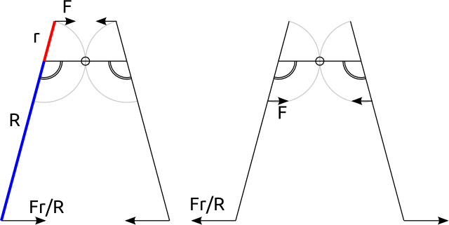
I have yet to verify Annirak's math but I felt it would be valuable to post a free body diagram of the nonrotated version. First, the drive pulley can support a tension differential F. This differential is what really moves the part so here are the two extremes.
Edited 2 time(s). Last edit at 09/12/2013 02:52PM by nicholas.seward.

Edited 2 time(s). Last edit at 09/12/2013 02:52PM by nicholas.seward.
|
Re: Grounded Experimental Delta Printer September 12, 2013 04:57PM |
Registered: 10 years ago Posts: 145 |
Hello Nicholas,
I believe the in your diagram the real levers are not r and R but the components of those distances that are parallel to the line that goes from the center of the line formed by the 2 force application points (center of the upper string) to the turning point. So, when the arm extends, that distance decreases, as does the torque at the turning point and then the force at the end of the arm, that by the way decreases as R increases.
So in theory, it should be easy to flex the arm in the extended position, but it would be increasingly difficult, as the lever would increase again. So, probably it will work as a way of auto-protection against unwanted flexing, probably springy.
And in the other side, closing the extended arm would requiere more force than closing an already-semi-closed arm (like in the second diagram). So, in less words, any movement is requieres less force the closer is the efective distance of the arm. Plase see the nex simplified diagram:
Well, you have the real device, you can experiment in the real world, but anyway, I believe it will work very fine.
I believe the in your diagram the real levers are not r and R but the components of those distances that are parallel to the line that goes from the center of the line formed by the 2 force application points (center of the upper string) to the turning point. So, when the arm extends, that distance decreases, as does the torque at the turning point and then the force at the end of the arm, that by the way decreases as R increases.
So in theory, it should be easy to flex the arm in the extended position, but it would be increasingly difficult, as the lever would increase again. So, probably it will work as a way of auto-protection against unwanted flexing, probably springy.
And in the other side, closing the extended arm would requiere more force than closing an already-semi-closed arm (like in the second diagram). So, in less words, any movement is requieres less force the closer is the efective distance of the arm. Plase see the nex simplified diagram:

Well, you have the real device, you can experiment in the real world, but anyway, I believe it will work very fine.
|
Re: Grounded Experimental Delta Printer September 12, 2013 05:09PM |
Registered: 10 years ago Posts: 979 |
|
Re: Grounded Experimental Delta Printer September 12, 2013 07:14PM |
Registered: 10 years ago Posts: 145 |
|
Re: Grounded Experimental Delta Printer September 13, 2013 03:35AM |
Registered: 15 years ago Posts: 401 |
|
Re: Grounded Experimental Delta Printer September 13, 2013 08:44AM |
Registered: 10 years ago Posts: 979 |
|
Re: Grounded Experimental Delta Printer September 16, 2013 01:31AM |
Registered: 10 years ago Posts: 979 |
|
Re: Grounded Experimental Delta Printer September 17, 2013 03:48AM |
Registered: 10 years ago Posts: 979 |
HE PRINTS!!!!!!!!!!!!!!!!!!!!!!!!!!!!!!
I think the infill was printing at 180mm/s. (I used some really old gcode and you can't just read it to find out the speed because it is in a weird coordinate system.) I will be doing more testing. This was just the first print I ever tried. (I used the speed up function in Repetier. There is no way I would have attempted this fast without a speed slider.)
I think the infill was printing at 180mm/s. (I used some really old gcode and you can't just read it to find out the speed because it is in a weird coordinate system.) I will be doing more testing. This was just the first print I ever tried. (I used the speed up function in Repetier. There is no way I would have attempted this fast without a speed slider.)
|
Re: Grounded Experimental Delta Printer September 17, 2013 05:29AM |
Registered: 15 years ago Posts: 401 |
That print looks pretty good!
I have to have a black-hat moment:
Can you ramp it up any more? Or did you hit a step-rate limit?
I have to have a black-hat moment:

Can you ramp it up any more? Or did you hit a step-rate limit?
|
Re: Grounded Experimental Delta Printer September 17, 2013 05:34AM |
Registered: 10 years ago Posts: 18 |
|
Re: Grounded Experimental Delta Printer September 17, 2013 09:34AM |
Registered: 10 years ago Posts: 979 |
@Annirak: The slider only went to 300%. From the hum of the steppers compared to when I did straight-line speed test, I would estimate that I could go up to 600mm/s before the stepper's start skipping. There is no way my filament drive could do that. My 24V power supply would be capable of heating that much plastic.
@TBog: Slic3r time is measured in minutes. Coordinated transformation and line segmentizing routine is measured in seconds.
@TBog: Slic3r time is measured in minutes. Coordinated transformation and line segmentizing routine is measured in seconds.
|
Re: Grounded Experimental Delta Printer September 17, 2013 10:46AM |
Registered: 10 years ago Posts: 100 |


Sorry, only registered users may post in this forum.