New arm design for Simpson style printer.
Posted by Guizmo
|
New arm design for Simpson style printer. August 07, 2013 06:44PM |
Registered: 10 years ago Posts: 145 |
Hello to everybody,
I'm new to this forum, and except for 2 or 3 posts made on the Nicholas Seward Simpson thread, this will be my first real contribution.
I certainly think Nicholas' design is brilliant and I feel inspired to improve it, although there is not much you can do. Annirak drive is great and I have to confess that I couldn't understand it at first, until I realized that with Annirak geometry you do not control an angle anymore, but a distance, thus, eliminating many non linearity problems. That's a great design!
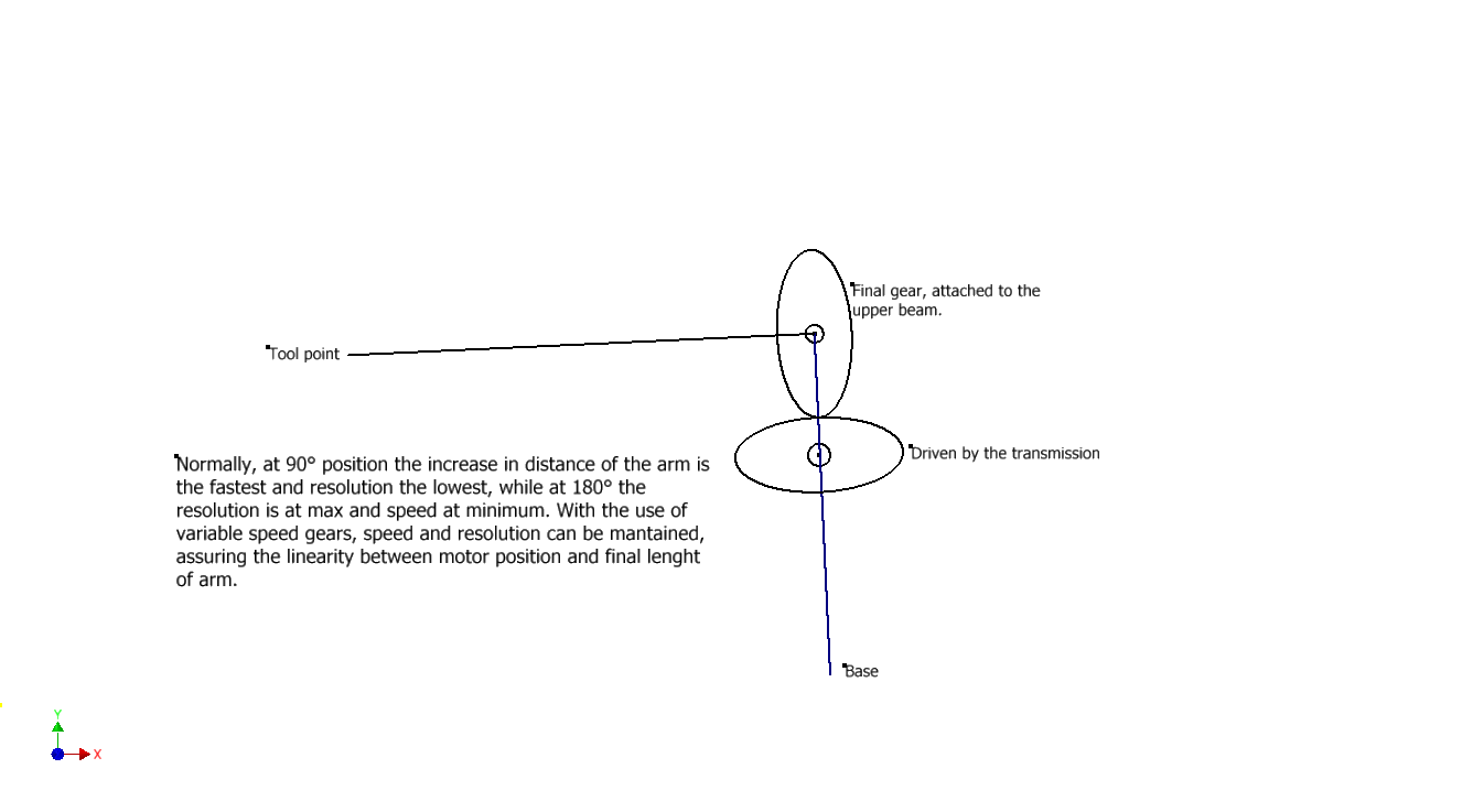
Then I thought: what is the downside of it? Well, now the non linearity gets swaped to the force, so you can apply less force (or generate more torque to turn the arm) the closer to 180 deg upper and lower arm are, and more force the closer to 90 deg they are(simplifying, I understand there are more things to consider). That really is not a downside, considering the printer doesn't need too much force and that there are 3 arms that very seldomly all will be close to 180 deg. position.
But...I wanted to design something different, closer to the original design of Simpson, by using a rotation driven mechanism and not the Annirak drive (which is great), just for the sake of it.
My idea, at this point, considers using gears to increase torque and translate the mechanical power from the motor to the driven axis. Problem is the non linearity (which N. Seward warned me about with something like: going away from Annirak drive will increase the complexity of the firmware, which is true), but I have an idea to solve that issue:
Using non circular gears at the last reduction step, I mean, gears that can have a variable torque/speed around and can be designed to compensate for the non linearity, working in fact like the Annirak drive but with gears, so I would expect to use the same firmware.
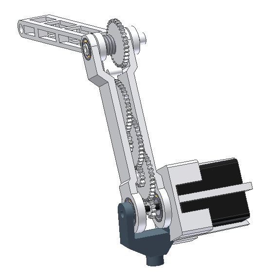
I attached a [very unfinished] image of the design and a sketch of the non circular gears.
What do you think? Of course, all of the gears should to be printed, getting closer to the dream of a completely printed machine. Oh, and the gears may not need to be elliptical. I have to calculate, but probably some excentric circular gears are all I need.
Ahh, backlash. I know that is the main issue with gears, but I am considering preloading the transmission with a rotating spring. I know that this is very likely to work as the arm needs to turn much less that 180 deg. The spring will make the gears touch only on one side of the theet, unless the motor is too quick and the spring couldn't react. I hope I can use it.
Ps: This is just a concept. Details of sizes, positions, bearings and more have to be carrefuly designed.
I'm new to this forum, and except for 2 or 3 posts made on the Nicholas Seward Simpson thread, this will be my first real contribution.
I certainly think Nicholas' design is brilliant and I feel inspired to improve it, although there is not much you can do. Annirak drive is great and I have to confess that I couldn't understand it at first, until I realized that with Annirak geometry you do not control an angle anymore, but a distance, thus, eliminating many non linearity problems. That's a great design!
Then I thought: what is the downside of it? Well, now the non linearity gets swaped to the force, so you can apply less force (or generate more torque to turn the arm) the closer to 180 deg upper and lower arm are, and more force the closer to 90 deg they are(simplifying, I understand there are more things to consider). That really is not a downside, considering the printer doesn't need too much force and that there are 3 arms that very seldomly all will be close to 180 deg. position.
But...I wanted to design something different, closer to the original design of Simpson, by using a rotation driven mechanism and not the Annirak drive (which is great), just for the sake of it.
My idea, at this point, considers using gears to increase torque and translate the mechanical power from the motor to the driven axis. Problem is the non linearity (which N. Seward warned me about with something like: going away from Annirak drive will increase the complexity of the firmware, which is true), but I have an idea to solve that issue:
Using non circular gears at the last reduction step, I mean, gears that can have a variable torque/speed around and can be designed to compensate for the non linearity, working in fact like the Annirak drive but with gears, so I would expect to use the same firmware.
I attached a [very unfinished] image of the design and a sketch of the non circular gears.
What do you think? Of course, all of the gears should to be printed, getting closer to the dream of a completely printed machine. Oh, and the gears may not need to be elliptical. I have to calculate, but probably some excentric circular gears are all I need.
Ahh, backlash. I know that is the main issue with gears, but I am considering preloading the transmission with a rotating spring. I know that this is very likely to work as the arm needs to turn much less that 180 deg. The spring will make the gears touch only on one side of the theet, unless the motor is too quick and the spring couldn't react. I hope I can use it.
Ps: This is just a concept. Details of sizes, positions, bearings and more have to be carrefuly designed.
|
Re: New arm design for Simpson style printer. August 07, 2013 07:02PM |
Registered: 10 years ago Posts: 979 |
How about replacing your oval gears with a Double Lamina Compliant Joint? In principle, a DLCJ should be able to replace any gear pair as long as you limit the rotation. That is not a problem with this design. This will get rid of all your backlash without a spring.
BTW, I hate you a little bit now. I am just about to drive myself crazy. It is all I can do not to design a DLCJ that has the properties of an Annirak Drive.
BTW, I hate you a little bit now. I am just about to drive myself crazy. It is all I can do not to design a DLCJ that has the properties of an Annirak Drive.
|
Re: New arm design for Simpson style printer. August 08, 2013 10:44AM |
Registered: 10 years ago Posts: 145 |
 .
.
|
Re: New arm design for Simpson style printer. August 08, 2013 11:14AM |
Registered: 10 years ago Posts: 145 |
Ok, now I know. I found the Wally thread and I understand the principle. Problem is, that would eliminate the backlash for the last pair of gears, but not for the pairs remaining, that by the way, have to turn more than 360 deg. Anyway, I think DLCJ are good and will try to incorporate them.
I really would like to get rid of that spring. Another idea to eliminate backlash is to use 2 gear trains, one for turning one way and viceversa. Problem is those would be a lot of gears. I have to think more.
I really would like to get rid of that spring. Another idea to eliminate backlash is to use 2 gear trains, one for turning one way and viceversa. Problem is those would be a lot of gears. I have to think more.
|
Re: New arm design for Simpson style printer. August 08, 2013 12:37PM |
Registered: 10 years ago Posts: 979 |
I like the gear train idea. I like it so much that I have tried it in the past. My findings were that the backlash is almost impossible to mitigate and the friction gets pretty unreasonable.
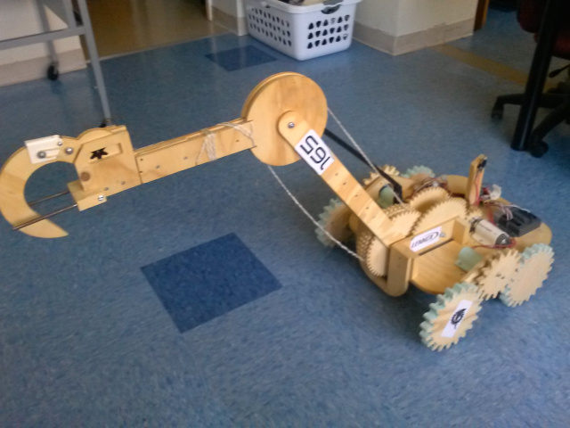
I am a coach for a high school robotics team and we have learned that if you can do something with string instead of gears that is preferable.
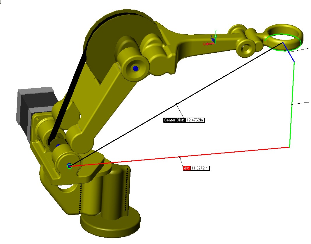
Here you can see one of our robots. You can see that both motors sit on the base plate and we run string up to the elbow to drive it. I would suggest something similar for you. Have a small drive pulley and a large elbow pulley that is then connected to your noncircular DLCJ. I am drawing ovals for now but it will probably need to be something else entirely.
You are not limited to 360 degrees. The drive pulley can have the string wrapped around it multiple times. You can also fix the string to both pulleys so you are using just string tensions to drive your arm and don't have to rely on friction.
Edited 2 time(s). Last edit at 08/08/2013 12:41PM by nicholas.seward.
I am a coach for a high school robotics team and we have learned that if you can do something with string instead of gears that is preferable.

Here you can see one of our robots. You can see that both motors sit on the base plate and we run string up to the elbow to drive it. I would suggest something similar for you. Have a small drive pulley and a large elbow pulley that is then connected to your noncircular DLCJ. I am drawing ovals for now but it will probably need to be something else entirely.

You are not limited to 360 degrees. The drive pulley can have the string wrapped around it multiple times. You can also fix the string to both pulleys so you are using just string tensions to drive your arm and don't have to rely on friction.
Edited 2 time(s). Last edit at 08/08/2013 12:41PM by nicholas.seward.
|
Re: New arm design for Simpson style printer. August 08, 2013 03:52PM |
Registered: 10 years ago Posts: 145 |
|
Re: New arm design for Simpson style printer. August 08, 2013 08:49PM |
Registered: 10 years ago Posts: 979 |
I banged out some math real quick. I will have to revisit it to verify that I am not blowing smoke but here is what I think the gear ratio needs to be with respect to the angle that the arms make with each other.
I roughed out one way this could manifest itself.
Edited 3 time(s). Last edit at 08/08/2013 08:52PM by nicholas.seward.
I roughed out one way this could manifest itself.

Edited 3 time(s). Last edit at 08/08/2013 08:52PM by nicholas.seward.
|
Re: New arm design for Simpson style printer. August 09, 2013 01:33AM |
Registered: 10 years ago Posts: 979 |

|
Re: New arm design for Simpson style printer. August 09, 2013 09:54AM |
Registered: 10 years ago Posts: 1,381 |

Guizmo, Nicholas Seward:
I like the combination of the zero back lash of the Double Lamina Compliant Joint (DLCJ) bearing/joint, and the non linear toothless elliptical gear or cam correction as it affords weight, and part count reduction, moreover it works with the Simpson firm ware without further modifications!
I believe I have a solution (or a starting point for discussion) that incorporates both the DLCJ bearing/joint, and the elliptical gear/cam, please see attached blueprints.
Comments/Notes/Questions:
I'm using wide control arms/linkages to help increase rigidity (side-to-side sway), and I have eliminated the tie rods that connect adjacent DLCJ bearings. In addition, I added DLCJ bearings to the upper shoulder pivot (stepper motor axis), and to the wrist joint (end effector).
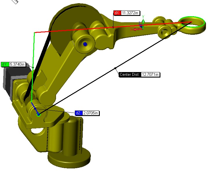
For reference, the DLCJ bearings are 1 inch wide (not shown), the DLCJ bearings center to center distance is 2.5 inches, and with an over all width of 3.75 inches. That's worst case, I have not taken advantage of all the surface area for tethering/binding.
The elbow pivot was given enough clearance for a 4 inch diameter pulley, for a 4:1 ratio from the stepper motor pulley. For reference, I have drawn in a 2 inch diameter timing pulley in the forearm joint.
The arms are 6 inches long measured from the distal pivot of the arm, to the furthest DLCJ pivot, and the elliptical toothless gears are for reference only. The longest part is 6 inches.
To adjust the timing belt tension the upper arm needs to be constructed of two parts (not shown). I'm considering guides of some flavor, plus dual turnbuckles or jack-screws.
Can you utilize the DLCJ bearing on the pivotal base/pedestal (vertical axis of rotation)?
Can the Simpson firmware be used in it's current configuration without modifications for the power train that I have drawn?
Is the elliptical gear or cam profile scalable, or does the profile need to be recalculated for a given arm length?
What plastic material will be used most often with this design? I would like to get a rough idea of what the wall thickness should be. I'm also thinking of shelling the part, and adding ribs in critical areas, instead of using 20% infilling. Will the shrink rate and warping be acceptable with no infilling, or does the infilling help prevent warping?
I appreciate your feedback, and I'm looking forward to a geometric solution.
A2
Edited 2 time(s). Last edit at 08/10/2013 01:43AM by A2.
Attachments:
open | download - ScreenHunter_07 Aug. 09 04.47.jpg (28.5 KB)
open | download - ScreenHunter_09 Aug. 09 04.51.jpg (46.6 KB)
open | download - ScreenHunter_10 Aug. 09 04.53.jpg (33 KB)
open | download - ScreenHunter_12 Aug. 09 06.53.jpg (57 KB)
open | download - ScreenHunter_13 Aug. 09 06.54.jpg (49.2 KB)
open | download - ScreenHunter_14 Aug. 09 06.55.jpg (61.5 KB)
open | download - ScreenHunter_15 Aug. 09 06.59.jpg (27.5 KB)
|
Re: New arm design for Simpson style printer. August 09, 2013 04:00PM |
Registered: 10 years ago Posts: 145 |
nicholas.seward Wrote:
-------------------------------------------------------
>
>
> Here is a better visualization. Each movement
> consists of the red cam rotating 15 degrees and
> the arm ends moving 1 inch away from each other.
Hey Nicholas!
Now I'm sure, very sure...
... you are kinda crazy! Lol
Well, good job, now i'm hating you a little bit, haha. You are fast, fast. I'm struggling with the math and you have already simulated. I supposed you are not married, right?
Anyway, I figured out some properties of the sistem and I found that the solution gets very complicated when the arms are not of equal lenght. I ended up with something similar to your solution that is on the graph:
With less words, the solution is the derivate of the equation that describes the change of lenght versus angle, and the other "gear" is just calculated to mantain the center to center distance, right?
By the way, how do you attach an image to be able to see it, without using services like Photobucket or so?
Edited 1 time(s). Last edit at 08/09/2013 05:05PM by Guizmo.
-------------------------------------------------------
>
>
> Here is a better visualization. Each movement
> consists of the red cam rotating 15 degrees and
> the arm ends moving 1 inch away from each other.
Hey Nicholas!
Now I'm sure, very sure...
... you are kinda crazy! Lol
Well, good job, now i'm hating you a little bit, haha. You are fast, fast. I'm struggling with the math and you have already simulated. I supposed you are not married, right?
Anyway, I figured out some properties of the sistem and I found that the solution gets very complicated when the arms are not of equal lenght. I ended up with something similar to your solution that is on the graph:


With less words, the solution is the derivate of the equation that describes the change of lenght versus angle, and the other "gear" is just calculated to mantain the center to center distance, right?
By the way, how do you attach an image to be able to see it, without using services like Photobucket or so?
Edited 1 time(s). Last edit at 08/09/2013 05:05PM by Guizmo.
|
Re: New arm design for Simpson style printer. August 09, 2013 04:23PM |
Registered: 10 years ago Posts: 979 |
I am married to the coolest woman in the world. We do have a dedicated date night.
To show your attached image you have to go back after you do your initial post. Right click on your attached image and do a "copy url" and then go back to edit mode and use that in an image tag.
Beautiful graph of your cam profiles. Mine and yours look like they are from the same family so I guess we are on the right track.
Here is what I have for the math. I think it agrees with what you have. I flipped a sign above.
I wish I had time to prototype this but I don't. It is all up to you.
Edited 1 time(s). Last edit at 08/09/2013 04:25PM by nicholas.seward.
|
Re: New arm design for Simpson style printer. August 09, 2013 04:53PM |
Registered: 10 years ago Posts: 145 |
A2 Wrote:
-------------------------------------------------------
> Guizmo, Nicholas Seward:
>
> I like the combination of the zero back lash of
> the Double Lamina Compliant Joint (DLCJ)
> bearing/joint, and the non linear toothless
> elliptical gear or cam correction as it affords
> weight, and part count reduction, moreover it
> works with the Simpson firm ware without further
> modifications!
>
> I believe I have a solution (or a starting point
> for discussion) that incorporates both the DLCJ
> bearing/joint, and the elliptical gear/cam, please
> see attached blueprints.
>
>
> Comments/Notes/Questions:
>
> I'm using wide control arms/linkages to help
> increase rigidity (side-to-side sway), and I have
> eliminated the tie rods that connect adjacent DLCJ
> bearings. In addition, I added DLCJ bearings to
> the upper shoulder pivot (stepper motor axis), and
> to the wrist joint (end effector).
>
> For reference, the DLCJ bearings are 1 inch wide
> (not shown), the DLCJ bearings center to center
> distance is 2.5 inches, and with an over all width
> of 3.75 inches. That's worst case, I have not
> taken advantage of all the surface area for
> tethering/binding.
>
> The elbow pivot was given enough clearance for a 4
> inch diameter pulley, for a 4:1 ratio from the
> stepper motor pulley. For reference, I have drawn
> in a 2 inch diameter timing pulley in the forearm
> joint.
>
> The arms are 6 inches long measured from the
> distal pivot of the arm, to the furthest DLCJ
> pivot, and the elliptical toothless gears are for
> reference only. The longest part is 6 inches.
>
> To adjust the timing belt tension the upper arm
> needs to be constructed of two parts (not shown).
> I'm considering guides of some flavor, plus dual
> turnbuckles or jack-screws.
>
> Can you utilize the DLCJ bearing on the pivotal
> base/pedestal (vertical axis of rotation)?
>
> Can the Simpson firmware be used in it's current
> configuration without modifications for the power
> train that I have drawn?
>
> Is the elliptical gear or cam profile scalable, or
> does the profile need to be recalculated for a
> given arm length?
>
> What plastic material will be used most often with
> this design? I would like to get a rough idea of
> what the wall thickness should be. I'm also
> thinking of shelling the part, and adding ribs in
> critical areas, instead of using 20% infilling.
> Will the shrink rate and warping be acceptable
> with no infilling, or does the infilling help
> prevent warping?
>
> I appreciate your feedback, and I'm looking
> forward to a geometric solution.
>
> A2
Hello A2!
I'm glad you're interested in this design, as I also believe part reduction is a very good goal for any reprap, and specially for an already good design like Simpson (which I also believe is the most reprap-able machine at this time).
I have a few comments on your design:
For what I see, you are trying to use the DLCJ as a replacement to bearings, which is good. I imagine the first joint (closer to the motor) will work like a knee, and that is a brilliant idea, because the motor mount now can be in the same axis of rotation and is simplified a lot. But the driven joint wouldn't work in that configuration,because the center of rotation is located on the center of the first arm end, so, that is the position the second "cam" has to be, and that's all, I belive it could work fine [Note: Not true, the center of rotation moves along the line of simmetry and its distance from the contact point tends to infinity as the angle betwen arms is closer to zero] . I draw a mockup:
Please note that the centers of rotation are of the "more fixed" side of the DLCJ, so you have to measure the distances correctly. (Please correct me if I'm wrong) [I'm wrong, anyway, I believe something useful can be obtained from A2's idea of DLCJ instead of bearings. Let's make it work]
Regarding the lenght of arms, that is important. Well, it is important that both are the same lenght, because if they are different, the cams have to be different too. Anyway, it doesn't matter the lenght nor the size of the cams, the only thing important about the cams is that they mantain the ratio they are designed to mantain (which is variable). So, yes, the cams are scalable.
Regarding firmware and plastic I don't know. Can you believe I don't have a 3d printer? That is why I'm so interested in this design to be cheap and reliable. I wan t one!!!
Edit: Guys, I'm getting really excited!!
Edited 3 time(s). Last edit at 08/09/2013 06:01PM by Guizmo.
-------------------------------------------------------
> Guizmo, Nicholas Seward:
>
> I like the combination of the zero back lash of
> the Double Lamina Compliant Joint (DLCJ)
> bearing/joint, and the non linear toothless
> elliptical gear or cam correction as it affords
> weight, and part count reduction, moreover it
> works with the Simpson firm ware without further
> modifications!
>
> I believe I have a solution (or a starting point
> for discussion) that incorporates both the DLCJ
> bearing/joint, and the elliptical gear/cam, please
> see attached blueprints.
>
>
> Comments/Notes/Questions:
>
> I'm using wide control arms/linkages to help
> increase rigidity (side-to-side sway), and I have
> eliminated the tie rods that connect adjacent DLCJ
> bearings. In addition, I added DLCJ bearings to
> the upper shoulder pivot (stepper motor axis), and
> to the wrist joint (end effector).
>
> For reference, the DLCJ bearings are 1 inch wide
> (not shown), the DLCJ bearings center to center
> distance is 2.5 inches, and with an over all width
> of 3.75 inches. That's worst case, I have not
> taken advantage of all the surface area for
> tethering/binding.
>
> The elbow pivot was given enough clearance for a 4
> inch diameter pulley, for a 4:1 ratio from the
> stepper motor pulley. For reference, I have drawn
> in a 2 inch diameter timing pulley in the forearm
> joint.
>
> The arms are 6 inches long measured from the
> distal pivot of the arm, to the furthest DLCJ
> pivot, and the elliptical toothless gears are for
> reference only. The longest part is 6 inches.
>
> To adjust the timing belt tension the upper arm
> needs to be constructed of two parts (not shown).
> I'm considering guides of some flavor, plus dual
> turnbuckles or jack-screws.
>
> Can you utilize the DLCJ bearing on the pivotal
> base/pedestal (vertical axis of rotation)?
>
> Can the Simpson firmware be used in it's current
> configuration without modifications for the power
> train that I have drawn?
>
> Is the elliptical gear or cam profile scalable, or
> does the profile need to be recalculated for a
> given arm length?
>
> What plastic material will be used most often with
> this design? I would like to get a rough idea of
> what the wall thickness should be. I'm also
> thinking of shelling the part, and adding ribs in
> critical areas, instead of using 20% infilling.
> Will the shrink rate and warping be acceptable
> with no infilling, or does the infilling help
> prevent warping?
>
> I appreciate your feedback, and I'm looking
> forward to a geometric solution.
>
> A2
Hello A2!
I'm glad you're interested in this design, as I also believe part reduction is a very good goal for any reprap, and specially for an already good design like Simpson (which I also believe is the most reprap-able machine at this time).
I have a few comments on your design:
For what I see, you are trying to use the DLCJ as a replacement to bearings, which is good. I imagine the first joint (closer to the motor) will work like a knee, and that is a brilliant idea, because the motor mount now can be in the same axis of rotation and is simplified a lot. But the driven joint wouldn't work in that configuration,


Regarding the lenght of arms, that is important. Well, it is important that both are the same lenght, because if they are different, the cams have to be different too. Anyway, it doesn't matter the lenght nor the size of the cams, the only thing important about the cams is that they mantain the ratio they are designed to mantain (which is variable). So, yes, the cams are scalable.
Regarding firmware and plastic I don't know. Can you believe I don't have a 3d printer? That is why I'm so interested in this design to be cheap and reliable. I wan t one!!!
Edit: Guys, I'm getting really excited!!
Edited 3 time(s). Last edit at 08/09/2013 06:01PM by Guizmo.
|
Re: New arm design for Simpson style printer. August 09, 2013 05:56PM |
Registered: 10 years ago Posts: 145 |
|
Re: New arm design for Simpson style printer. August 09, 2013 06:56PM |
Registered: 10 years ago Posts: 145 |
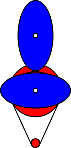
I believe we can design a hybrid between the DLCJ and the non circular gears, infact, it would be a DLCJ with variable ratio, allowing us to eliminate the bearings and at the same time working like the Annirak drive. Probably something like this:
Red line represents a spring and blue line represents fishing line that can be shortened to turn the joint.
Although I'm not very sure we need that "disposable knife"shape. Probably a simple more round shape will work, it has to be calculated.
Funny, but it looks more like the original Annirak drive now. I hope this can work. Less bearings sounds good to me.
|
Re: New arm design for Simpson style printer. August 09, 2013 07:01PM |
Registered: 10 years ago Posts: 979 |
|
Re: New arm design for Simpson style printer. August 09, 2013 07:08PM |
Registered: 10 years ago Posts: 979 |

|
Re: New arm design for Simpson style printer. August 10, 2013 12:40PM |
Registered: 10 years ago Posts: 3 |
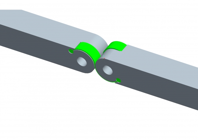
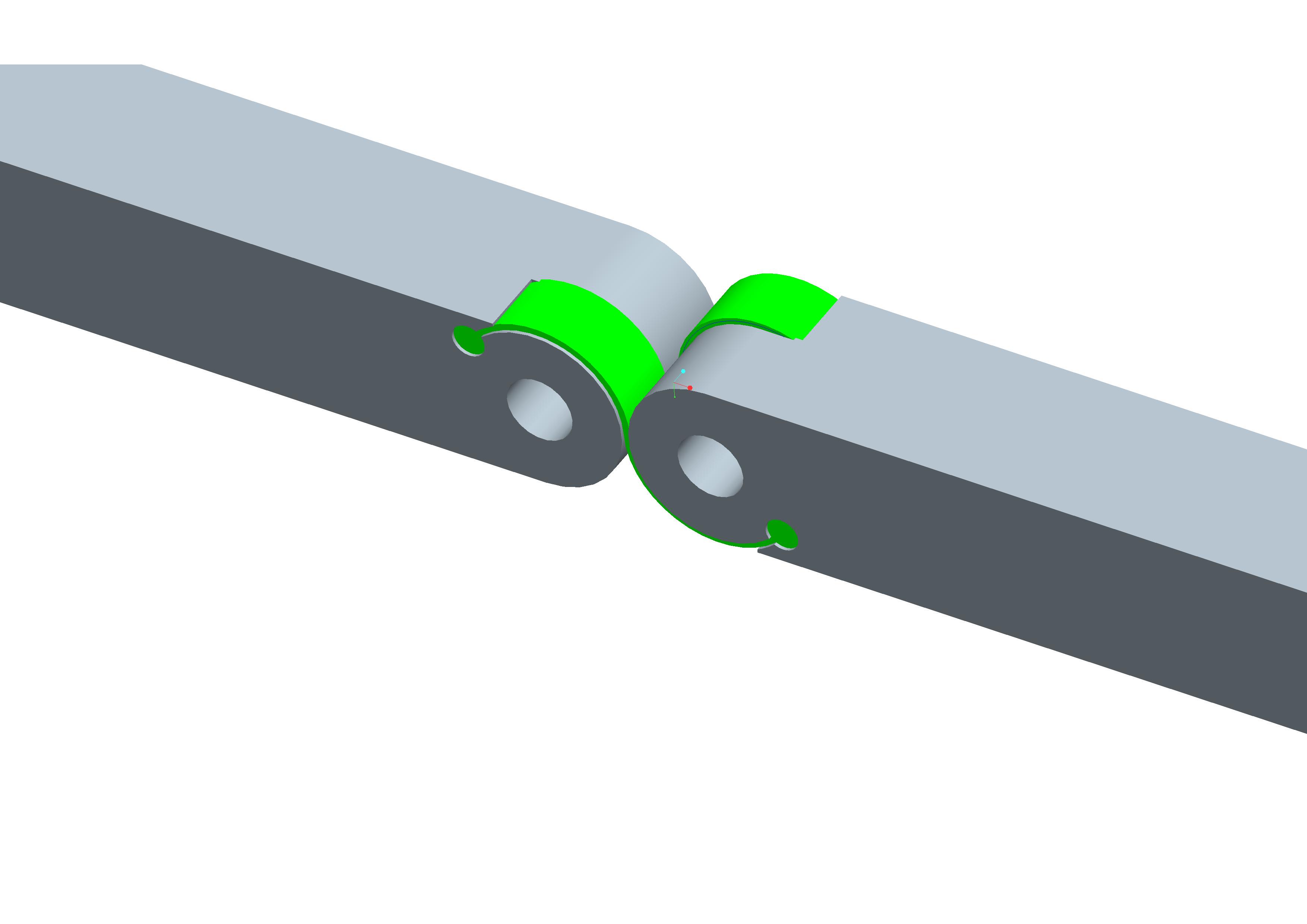
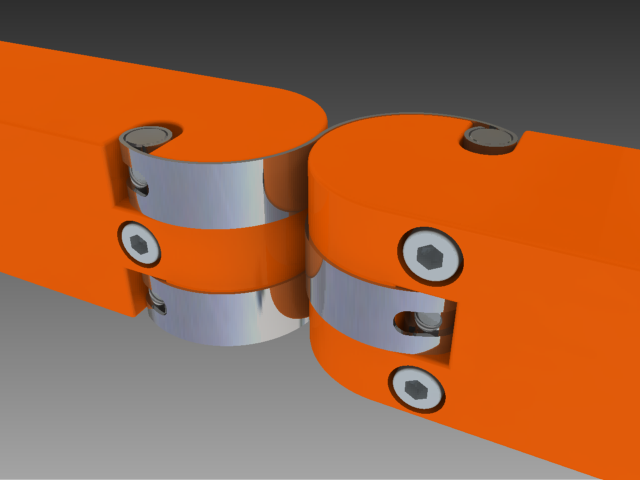
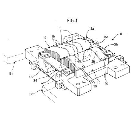
To get rid of the spring you could also replace the strings of the DLCJ with flexible blades , I have used such kind of self deploying articulations in the past
[www.casimages.com]]
[www.casimages.com]]

|
Re: New arm design for Simpson style printer. August 10, 2013 05:04PM |
Registered: 10 years ago Posts: 1,381 |
|
Re: New arm design for Simpson style printer. August 10, 2013 06:52PM |
Registered: 10 years ago Posts: 979 |

Here is how I would do the blades. You need 3 so you can balance the tension. I did some super quick sourcing and I could get the raw material for each individual blade for 25 cents. (You will need to make a stamp to cut out the slots on the end and you will have to form the ends. We could probably get a spring shop to make these for us.) With 608 bearings costing 25 cents this is not an immediately a winner.
Options: You could stick with the strings like I did on Wally. You could also use some other type of film or fabric. Nylon strapping comes to mind. That would take the cost down to pennies per strap. Could we print the straps in nylon?
Notes: A well tensioned setup like I have in the rendering should have very little axial play and would therefore be a good bearing replacement. I think I will play with the nylon straps (printed or woven) for the VRDLCJ. (Variable Ratio Double Lamina Compliant Joint) Of course, that will be months from now. I hope someone else can test this first.
My wife and I kept on trying to pronounce VRDLCJ. We kept saying Virgil. I propose we call it a Virgil Joint.
@A2: I have never heard about Rolamite bearings. Thanks so much for bringing them to my attention.
Edited 1 time(s). Last edit at 08/10/2013 06:52PM by nicholas.seward.
|
Re: New arm design for Simpson style printer. August 10, 2013 09:07PM |
Registered: 10 years ago Posts: 1,381 |
Nice looking render, and solution Nicholas!
There is a name for this style of frictionless joint, but the name escapes me.
Nylon Zip ties have been successfully 3D printed, and would be a natural first choice, as it's some thing a 3D printer can replicate.
I like the idea of using thin steel shim stock for the ribbon.
Thin shim stock can typically be cut with a pair of scissors, or with a hand punch.
A2
|
Re: New arm design for Simpson style printer. August 10, 2013 09:36PM |
Registered: 10 years ago Posts: 979 |
|
Re: New arm design for Simpson style printer. August 10, 2013 10:06PM |
Registered: 10 years ago Posts: 1,381 |
Double lamina compliant joint (DLCJ).
I believe that the hinge that you and Nicope have drawn up has another name, and I'm unable to find a picture to help my memory.
This joint is often assumed to be related to the rolamite bearing. But because there is no box or sliding action it is different. I thought of it when I saw the DLCJ joint constructed with thread on Wally, and I was curious if it was related. I've also seen instrumentation with this style of joint (metal ribbons), it's slippery
A2
|
Re: New arm design for Simpson style printer. August 10, 2013 10:26PM |
Registered: 10 years ago Posts: 1,381 |

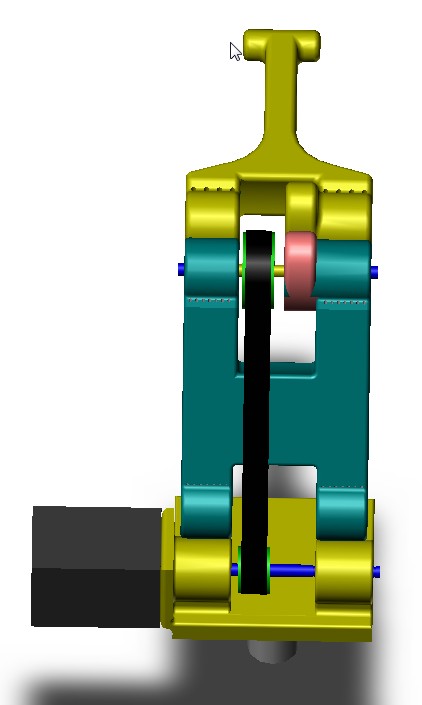
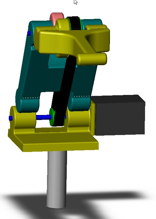
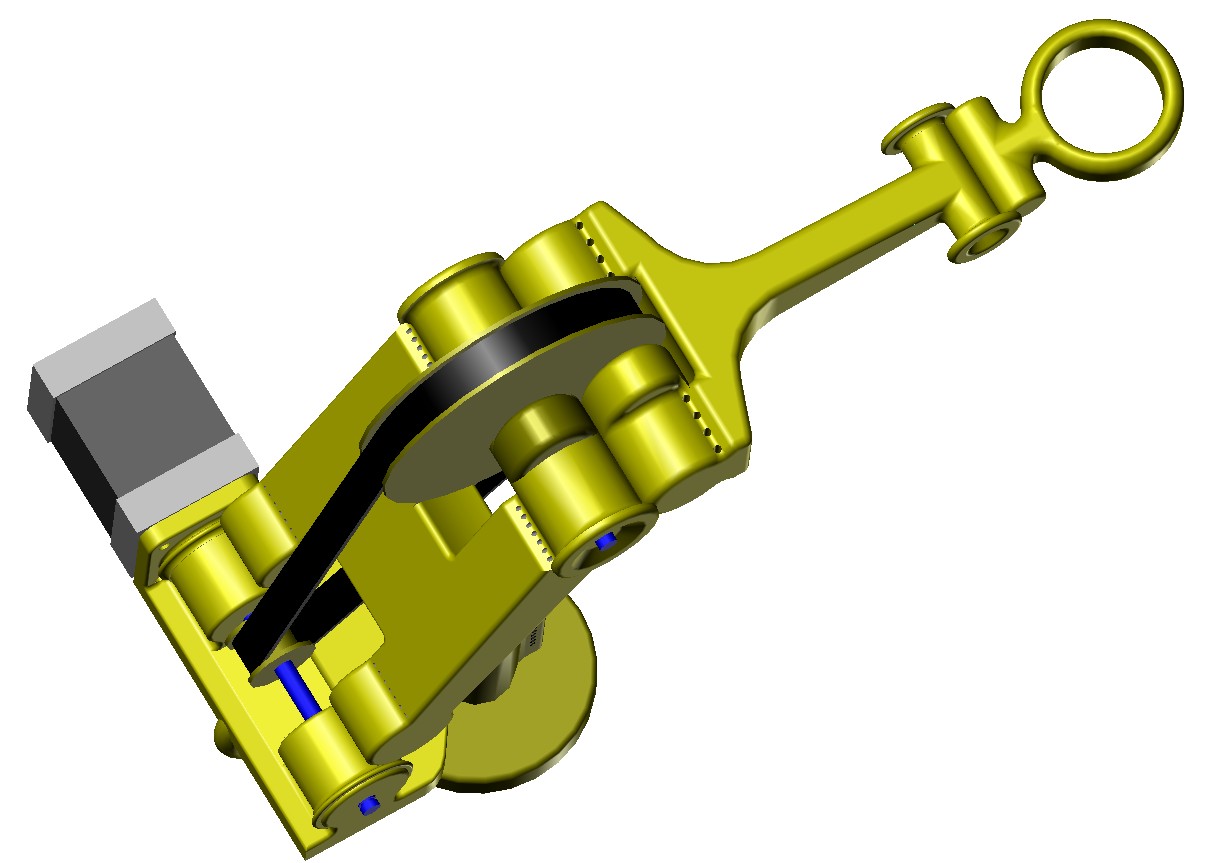
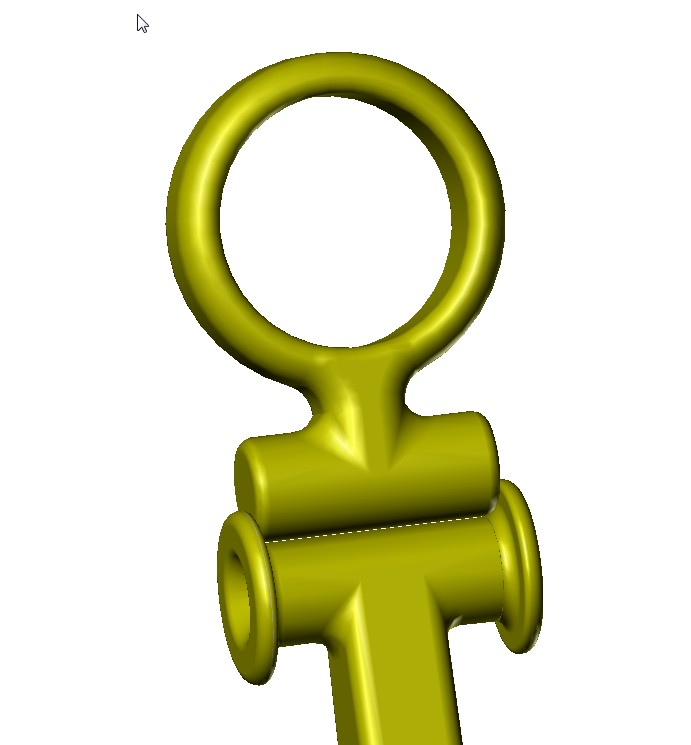
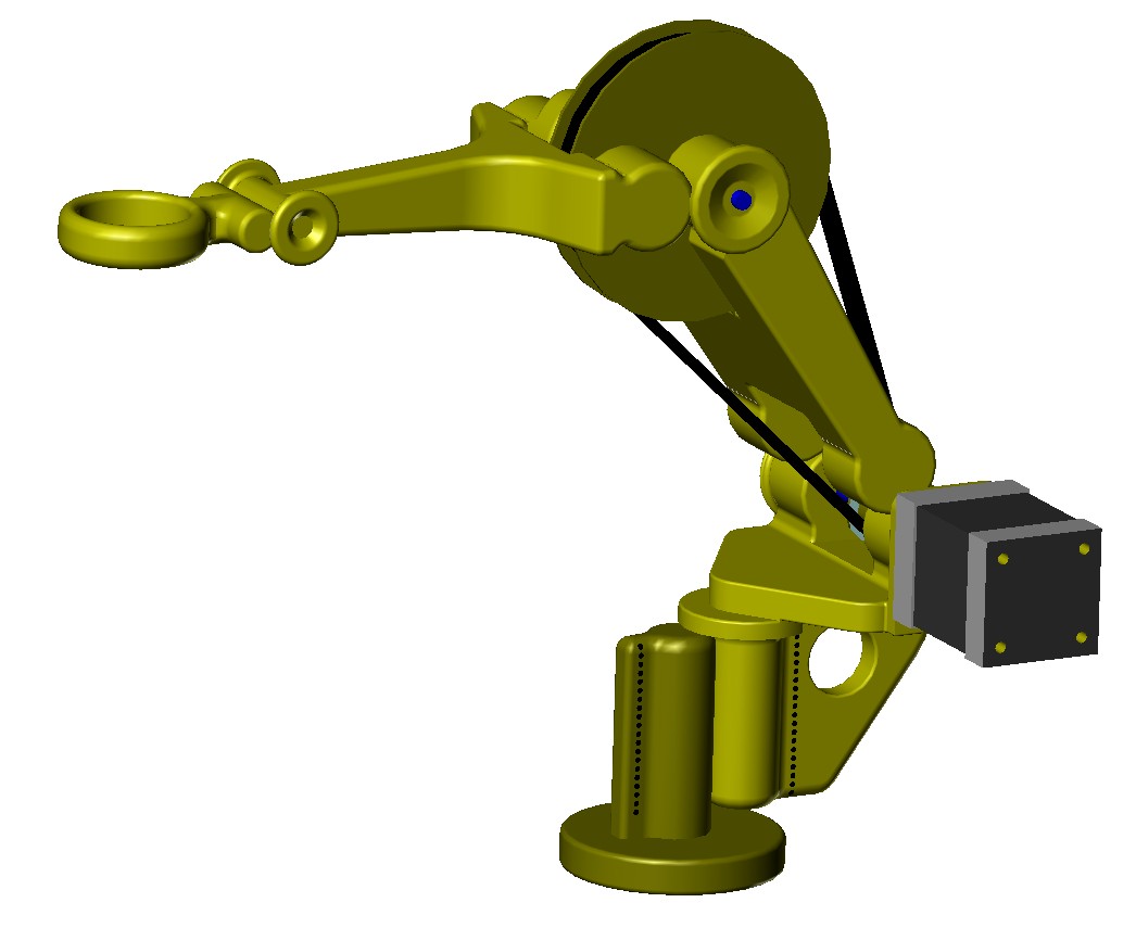
All components that are dark yellow can be printed, (see attached images). It appears that the hardware part count will be low.
I'm designing this robot to fit on existing reprap beds, this will allow the smaller 3D printers to breed larger 3D printers. I'm going to limit the max part size to 6 inches x 4 inches x 4 inches, moreover it's cheaper to mail a smaller lighter package of parts to your friends
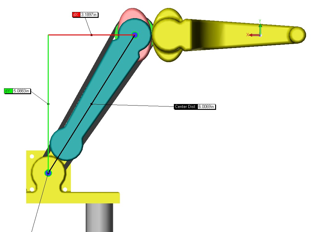
Location of the cam utilizing equal length arms:
As design considerations go for this project, the cam location, and profile is very important, as so many other components have to be designed around it's function, location, size, and geometry.
Because of the design limitation of a maximum component length of 6 inches, I would like to keep the present location of the cams as I have drawn if it's reasonable to do so? I envision what I have drawn will work, but I don't know how to calculate the cam profile to validate my idea, this is because I don't know what exactly is being solved, and I do not recognize the maths. I'm going to continue improving the design that I have started until a solution is made clear to me.
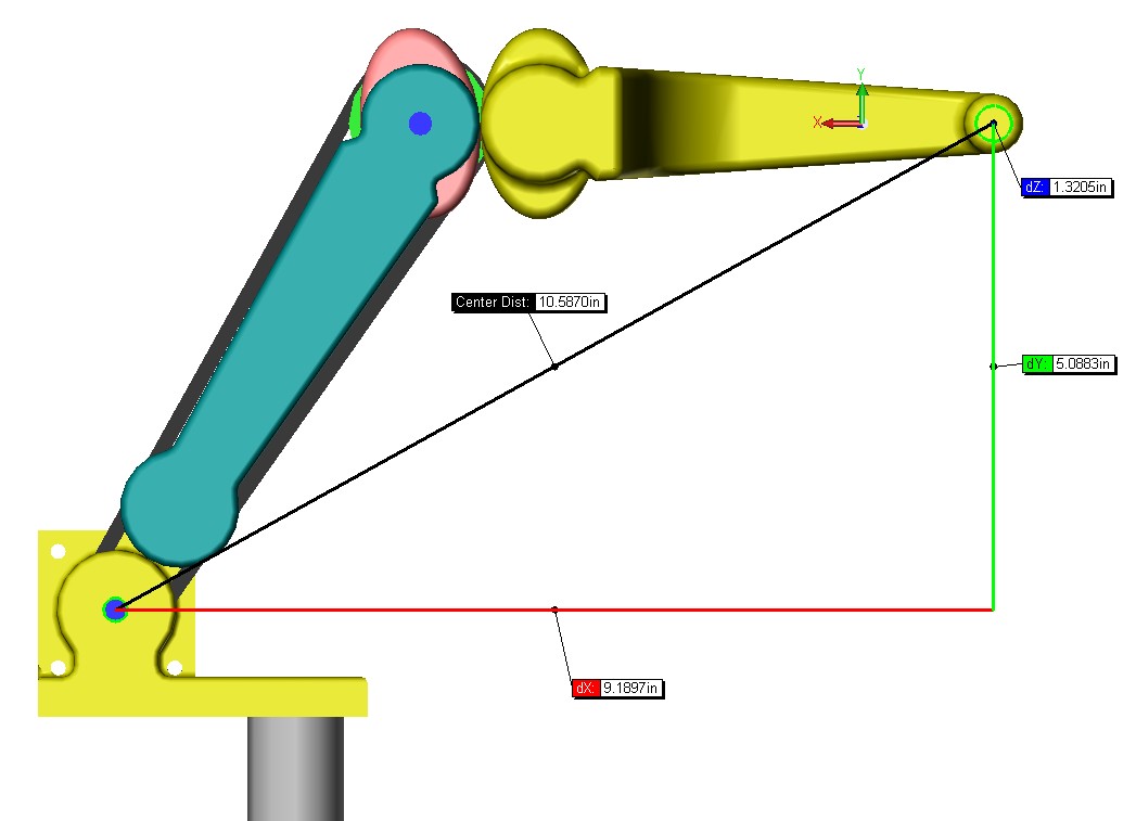
Advantages of locating the driven cam between the DLCJ elbow pivot are:
(see attached images)
1 Arm structure is more rigid, as less material is removed from the upper arm distal end to accommodate the driving cam, and timing pulley.
2 Allows you to mount the bearing and shaft for the timing pulley, and driver cam inside of the DLCJ pivot cylindrical geometry, offering more strength, rigidity, and a more compact solution.
3 A smaller reprap 3D printer can print all the plastic parts.
4 Low part count.
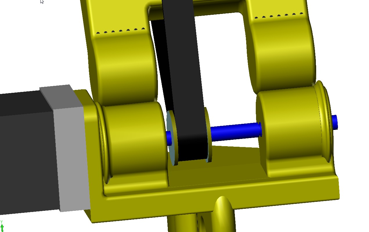
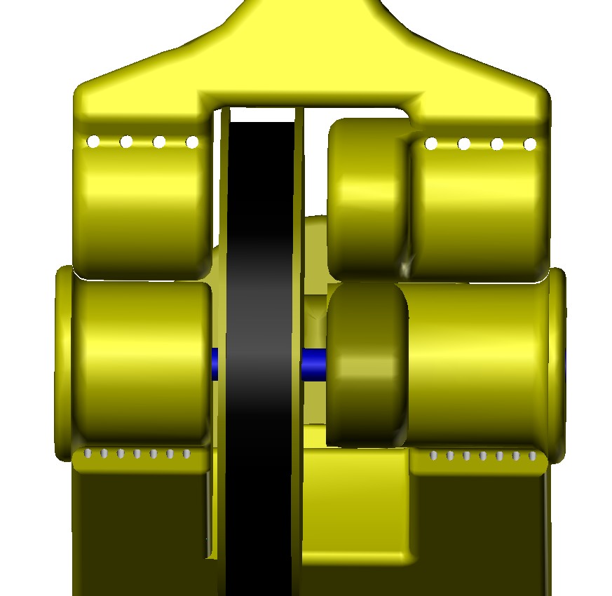
Joint guides were added:
(see attached images)
I have added “joint guides” to the arm, just in case there are issues with the thread that I can't foresee, at minimum the guides will make aligning the thread holes easier.
I hope the guides are more for curb appeal than function
The guides are designed like a raceway for bearings. I think if I design the fit to be 1:1, the thread thickness will maintain a separation between the rolling surface and the guide. If the sidewalls are rubbing, I can either sand the radius down, or redesign the part. Nylon would be a good material to use, for most mating, and moving surfaces. if you didn't want the whole part to be printed of Nylon, you could print a small pad or button of Nylon and selectively choose the location.
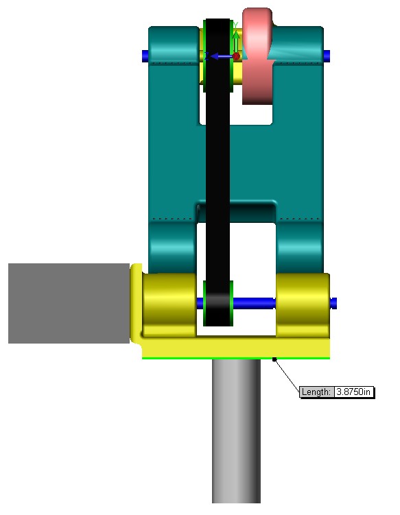
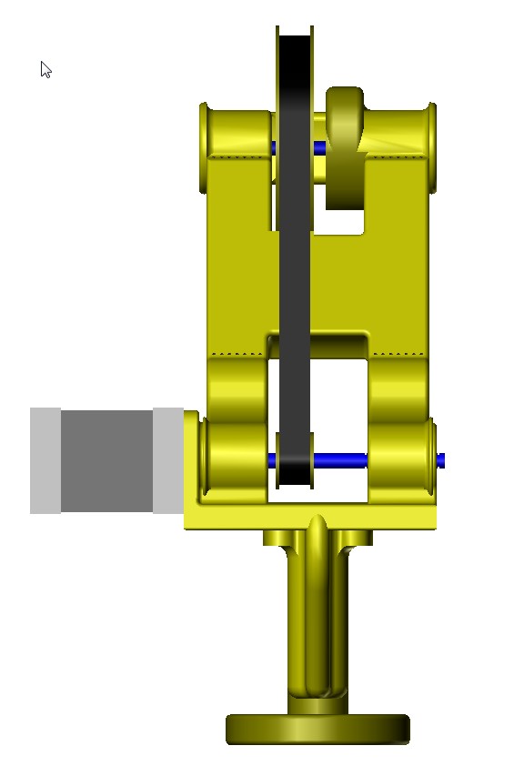
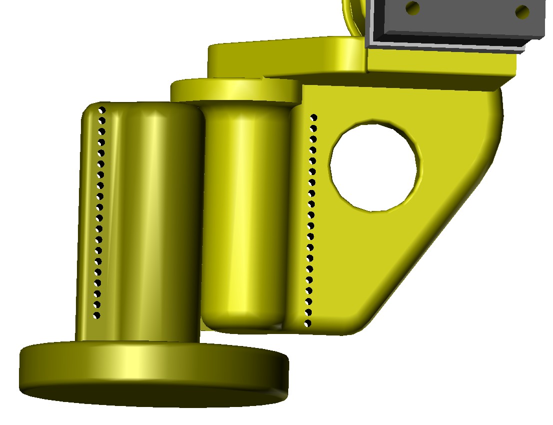
Pedestal/base pivot (vertical axis) DLCJ joint/bearing:
(see attached images)
A DLCJ bearing/pivot is integrated into the pedestal/base.
A support shelf with a fillet was added to restrict downward axial movement.
Any downward movement will force the fillet to push the base pivot shaft away from the opposing joint, and increase the tension on the threads.
I envision three methods to lash the DLCJ bearing/pivot:
1 Two counter rotating wraps, which start on either end of the pivot shaft.
2 One continuous wrap from the top to the bottom of the pivot shaft.
3 Two continuous counter rotating wraps from the top to the bottom of the pivot shaft.
Driven from the top/elbow:
This design eliminates the return spring, but reintroduces optical homing or micro switch. So turning the robot off will not automatically reset the homing location as it does with the original Simpson design. Can the Simpson firmware work with a homing switch like an optical switch/relay?
Timing belt tension, means for adjustment, and replacement:
To maintain tension on the timing belt I will design the upper arm to slide inside of the lower half, with a means to lock the two halves in place.
Tolerance stack up error of the total arm length, firmware issue?:
Should I subtract the thickness of the thread from the length of the arm? The thread thickness will push the arms away from each other, thus increasing the over all length/reach of the robot arms.
There are 3 DLCJ joints, if the thread diameter is .013 inch, (3*.013 = .039 inch or 1 mm)
1 mm of stack up error in the length of the arm, is that acceptable, easy to compensate with software?
Thank you for your valued feed back, and I look forward to a solution to the location of the cam, and of it's profile.
A2
Edited 3 time(s). Last edit at 08/11/2013 12:15AM by A2.
Attachments:
open | download - ScreenHunter_39 Aug. 10 19.52.jpg (90.6 KB)
open | download - ScreenHunter_40 Aug. 10 20.13.jpg (92.6 KB)
open | download - ScreenHunter_41 Aug. 10 20.13.jpg (30.4 KB)
open | download - ScreenHunter_42 Aug. 10 20.14.jpg (80.5 KB)
open | download - ScreenHunter_43 Aug. 10 20.15.jpg (64.6 KB)
open | download - ScreenHunter_44 Aug. 10 20.15.jpg (39.6 KB)
open | download - ScreenHunter_45 Aug. 10 20.16.jpg (62.9 KB)
open | download - ScreenHunter_46 Aug. 10 20.17.jpg (77.4 KB)
open | download - ScreenHunter_47 Aug. 10 22.19.jpg (58.8 KB)
|
Re: New arm design for Simpson style printer. August 11, 2013 04:47AM |
Registered: 10 years ago Posts: 979 |
First, I think a complete DLCJ solution for Simpson would be great. It would allow the removal of all the bearings and M8 bolts.
Microswitch homing would be good. I don't use custom firmware yet. Generic firmware will be able to home to the microswitches. (I do the coordinate transformation in software for now. Not that it can't go into firmware. Not all my designs can fit in firmware so I am developing a unified tool-chain that will work for anything I do.)
A well designed DLCJ will not have the string pushing the arms apart. The string drum should be smaller than the contact drum. This keeps the string from getting repetitively crushed. This also allows the string tension to more directly pull the two sides together. See my video below.
Guides are a good idea. I am playing with the idea of a segmented (cut outs for the string to sit in) herringbone gear to prevent axial shift and to provide some rotational alignment during assembly.
I am not sure what you mean by the different wrapping methods that you mentioned. I would suggest 1 repeated figure-8 pattern from top to bottom.
Drum roll............
I covered a few pages of paper with math and did some iterative programming to find a proportional drive solution. I always love it when complex math leads to a simple solution. This is such an elegant solution that I am considering it for my beta run. I will have to see.
Edited 1 time(s). Last edit at 08/11/2013 04:49AM by nicholas.seward.
Microswitch homing would be good. I don't use custom firmware yet. Generic firmware will be able to home to the microswitches. (I do the coordinate transformation in software for now. Not that it can't go into firmware. Not all my designs can fit in firmware so I am developing a unified tool-chain that will work for anything I do.)
A well designed DLCJ will not have the string pushing the arms apart. The string drum should be smaller than the contact drum. This keeps the string from getting repetitively crushed. This also allows the string tension to more directly pull the two sides together. See my video below.
Guides are a good idea. I am playing with the idea of a segmented (cut outs for the string to sit in) herringbone gear to prevent axial shift and to provide some rotational alignment during assembly.
I am not sure what you mean by the different wrapping methods that you mentioned. I would suggest 1 repeated figure-8 pattern from top to bottom.
Drum roll............

I covered a few pages of paper with math and did some iterative programming to find a proportional drive solution. I always love it when complex math leads to a simple solution. This is such an elegant solution that I am considering it for my beta run. I will have to see.
Edited 1 time(s). Last edit at 08/11/2013 04:49AM by nicholas.seward.
|
Re: New arm design for Simpson style printer. August 11, 2013 06:53AM |
Registered: 10 years ago Posts: 3 |
Well, after a quick research the thing I was thinking about is very different from my memory, and there are patents on it...
I like the way you're going, and I hope some day you will have the time to show us your math, it's amazing to me how quick you are
I like the way you're going, and I hope some day you will have the time to show us your math, it's amazing to me how quick you are
|
Re: New arm design for Simpson style printer. August 11, 2013 09:04PM |
Registered: 10 years ago Posts: 14 |
On the VRDLCJ image there, are the main arcs circular?
Also, I'm curious how you'd drive this. A line across the tip (as Guizmo draws) would let you extend the arm, but how would you contract it? A closed belt comes to mind, but I'm having a hard time identifying a fixed perimeter path for the belt. Perhaps a well placed evolute to keep tension as the joint rolls?
Edited 1 time(s). Last edit at 08/11/2013 09:17PM by Shawn.Walker.
|
Re: New arm design for Simpson style printer. August 11, 2013 09:40PM |
Registered: 10 years ago Posts: 979 |
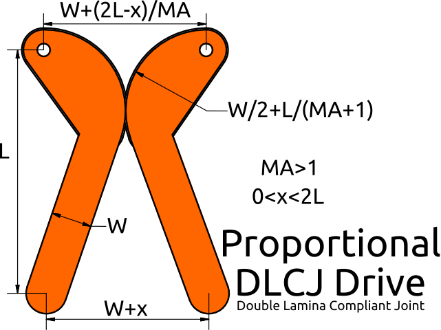
All the arcs are circular on the Proportion DLCJ Drive. It is a one-way drive. (Simpson just needs to extend the arm. Gravity will do the work to contract.) You drive it by a block and tackle between the holes I have put in the picture. It is possible to do a two-way drive without fanciness. I am working on a mathematically equivalent linkage that will be able to demonstrate the two-way drive.
Edited 1 time(s). Last edit at 08/12/2013 11:32AM by nicholas.seward.
Edited 1 time(s). Last edit at 08/12/2013 11:32AM by nicholas.seward.
|
Re: New arm design for Simpson style printer. August 12, 2013 03:50PM |
Registered: 10 years ago Posts: 1,381 |

@Nicholas Seward,
Nice looking pair of robot arms!
Tks for the explanation, and for stating that the cam form is circular, so your goal is to calculate a radius.
Roughly to my unaided eye, it looks like the radius of the cam is 20% to 30% of the length of the arm. I have estimated that the cam radius for my 6 inch arms to be 1.5 inches. I'm going with 1.5 inches until I understand the math. Because your arms are using the block and tackle, and the two holes, and a few of your input values are unknown to me, I'm unsure of where I should take my measurements.
I'm wondering if a fixed percentage of any arm length (center to center), could work.?
Edit 1:
Are you are free wheeling the stepper motor, when the arms of the Simpson with springs (block and tackle) lift up? If you are free wheeling, does the timing belt pulley driven arm (like what I have drawn) necessitate reverting back a small portion of the original code, (i.e. uncommenting the original code)?
Edit 2:
Added a picture of a chunky looking arm, it's less than 6 inches long. A 3 inch diameter timing belt pulley is show.
A2
Edited 5 time(s). Last edit at 08/12/2013 04:41PM by A2.
|
Re: New arm design for Simpson style printer. August 12, 2013 04:03PM |
Registered: 10 years ago Posts: 979 |
Any radius will do. It all depends on how bulky you want the arms. You can technically make your arms half circles. Use the equations I listed above to design around a mechanical advantage (MA). I did not draw it in but the arm ends and the arc center are all in a straight line. I am currently working on a Herringbone style arm that can easily be driven two ways. I hope to post soon.
|
Re: New arm design for Simpson style printer. August 12, 2013 05:20PM |
Registered: 10 years ago Posts: 979 |

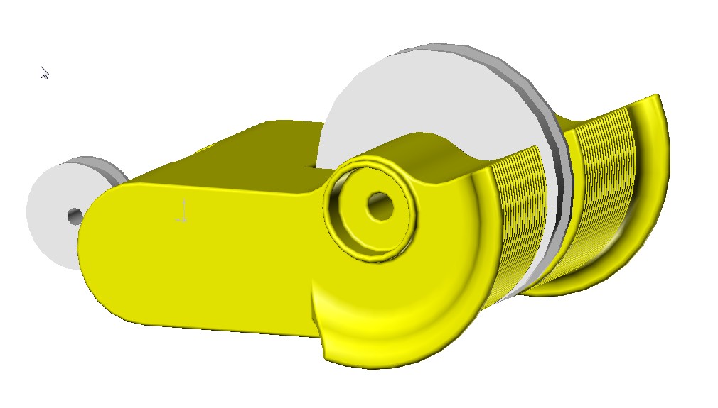
Okay, this should simplify the design quite a bit.
1) Pick any gear size that works for your design.
2) Place two holes along the arm's axis an equal distance from the gear's center. These will be used for your two sided drive. (The sum of the distances between the top holes and the bottom holes is a constant making it perfect for a closed circuit.)
I used herringbone gears for axial and rotational alignment. I offset the herringbone gears from side to side by 1/2 of a tooth. This allows you to use the same part for both sides of the design. You could use string or nylon tip ties to hold this together. It would be easy to add tension from the back of the arm. Additionally, this looks very printable. I made the helical angle 45 degrees to aid in the printability.
Edited 2 time(s). Last edit at 08/12/2013 09:07PM by nicholas.seward.

Sorry, only registered users may post in this forum.