New arm design for Simpson style printer.
Posted by Guizmo
|
Re: New arm design for Simpson style printer. September 18, 2013 09:27PM |
Registered: 10 years ago Posts: 31 |
Very interesting rope info. I always use the flake method for dealing with my vacuum cleaner cord, but I never knew to call it that. Sometimes I wind line around palm and elbow crossing over midway to make a figure 8, but there's a limit to how long a line you can do that with before it slides free of your elbow!
Using bushings with a spinning nail doesn't get you off for free. Any play in the bushings and any bend in the nail will cause erratic positioning in certain joint angle ranges.
Sliding around a bolt as Nicholas is doing avoids these problems very well. Even if the bolt is not truly round, the distortion in position will be small, and will occur repeatably as a function of joint angle, so it could be calibrated away if necessary.
But you do have to use very slippery line to be able to pull it around more than one turn! If the slippery coating wears off, you'll just have to replace the line oftener.
So it might be important that it's easily re-strung.
|
Re: New arm design for Simpson style printer. September 19, 2013 02:39AM |
Registered: 10 years ago Posts: 1,381 |

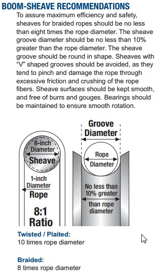
The adjacent article to the bending radius describes how to design a pulley (sheave) for braided line.
The diameter of the pulley is 8 times the rope diameter, and is mated to a round grove in the pulley. So the minimum bend radius is not what we are after, it's the diameter of the pulley.
Dia of pulley/bolt/nail, etc: 0.02” inch x 8 = 0.16” inch (4.0 mm).
A2
Edited 1 time(s). Last edit at 09/19/2013 02:42AM by A2.
|
Re: New arm design for Simpson style printer. September 22, 2013 06:28PM |
Registered: 10 years ago Posts: 1,381 |
@Nichloas, and beta testing team:
I'm interested in learning more about Simpsons performance/specifications/capabilities, etc, and a few more ideas.
Orientation bolt-pulley:
It looks like both Simpson No1 and No2 have reversed the pulley (bolt) orientation, and now have the line wrapping around the threaded portion of the M8 bolt vs. the smooth section of the shank, is this correct? I assume this was done to correct the line jumping problem?
If true, this would allow the use of a shorter bolt, and the diameter of the bolt could be reduced to 0.16” inch (4.0 mm). Advantages would be: increased mechanical advantage, weight savings, cheaper hardware, and eliminate the head of the bolt sticking out from the joint area.
Creep/Hysteresis:
A constant loading of 20 lbs on a tensioned cantilevered pulley could creep over time? If the structure is weakened over time from creep, and/or repeated flexing, some amount of hysteresis (lag) will be introduced when the system reverses direction. Or is the force on the cantilevered bolt not displacing the bolt-pulley?
It also looks like you added some material to the outside perimeter of the bolt-pulley hole, was that for alignment purposes or for strength?
If creep is a concern, in the user manual you can suggest to back off the tension when not in use to prevent creep deformation.
Creep (cold flow) test:
You can accelerate and test creep deformation in an oven. In general, 160F to 180F is a typical temperature range to begin testing plastics with. I guess if it's made of PLA it will melt.. lol
Creep (cold flow deformation)
[en.wikipedia.org])
Creep test video:
[www.youtube.com]
Repeatability A, B, C, axis test:
What is the repeatability of the A, B, and C axis over time +-0.0001” inch?,+-0.001” inch? +-0.010” inch?
Place a dial indicator inline with each arm. Then run a routine that move the arm in a triangular pattern.
Run the routine for 72 hours, and periodically take a recording.
What is the longest print time, and highest chamber temperature?
It would be nice to have a digital dial indicator with mini USB output, and a strip chart recorder to do the lab/techie recording work automatically for you.
Plywood CNC kit repeatability testing.
[www.youtube.com]
Dial indicator optical mouse encoder hack:
This might have other uses!
[www.youtube.com]
[www.youtube.com]
[www.youtube.com]
[www.youtube.com]
Microswitch location:
The microswitch can be located on the lower shoulder pivot near the platform base (vertical axis pivot). This would clean up the looks of it a little, as less wiring would be exposed, and this would reduce the part count.
The microswitch could be hidden within a pocket in the lower shoulder pivot. A molded in detent on the upper arm could impinge on the microswitch to activate it.
Repeatability limit swith/Hall effect sensor test:
This video shows an example of how to test the repeatability of an end stop switch.
G0704 Home/limit proximity switch repeatability test
[www.youtube.com]
A2
Edited 2 time(s). Last edit at 09/22/2013 09:25PM by A2.
I'm interested in learning more about Simpsons performance/specifications/capabilities, etc, and a few more ideas.
Orientation bolt-pulley:
It looks like both Simpson No1 and No2 have reversed the pulley (bolt) orientation, and now have the line wrapping around the threaded portion of the M8 bolt vs. the smooth section of the shank, is this correct? I assume this was done to correct the line jumping problem?
If true, this would allow the use of a shorter bolt, and the diameter of the bolt could be reduced to 0.16” inch (4.0 mm). Advantages would be: increased mechanical advantage, weight savings, cheaper hardware, and eliminate the head of the bolt sticking out from the joint area.
Creep/Hysteresis:
A constant loading of 20 lbs on a tensioned cantilevered pulley could creep over time? If the structure is weakened over time from creep, and/or repeated flexing, some amount of hysteresis (lag) will be introduced when the system reverses direction. Or is the force on the cantilevered bolt not displacing the bolt-pulley?
It also looks like you added some material to the outside perimeter of the bolt-pulley hole, was that for alignment purposes or for strength?
If creep is a concern, in the user manual you can suggest to back off the tension when not in use to prevent creep deformation.
Creep (cold flow) test:
You can accelerate and test creep deformation in an oven. In general, 160F to 180F is a typical temperature range to begin testing plastics with. I guess if it's made of PLA it will melt.. lol
Creep (cold flow deformation)
[en.wikipedia.org])
Creep test video:
[www.youtube.com]

Repeatability A, B, C, axis test:
What is the repeatability of the A, B, and C axis over time +-0.0001” inch?,+-0.001” inch? +-0.010” inch?
Place a dial indicator inline with each arm. Then run a routine that move the arm in a triangular pattern.
Run the routine for 72 hours, and periodically take a recording.
What is the longest print time, and highest chamber temperature?
It would be nice to have a digital dial indicator with mini USB output, and a strip chart recorder to do the lab/techie recording work automatically for you.
Plywood CNC kit repeatability testing.
[www.youtube.com]
Dial indicator optical mouse encoder hack:
This might have other uses!
[www.youtube.com]
[www.youtube.com]
[www.youtube.com]
[www.youtube.com]

Microswitch location:
The microswitch can be located on the lower shoulder pivot near the platform base (vertical axis pivot). This would clean up the looks of it a little, as less wiring would be exposed, and this would reduce the part count.
The microswitch could be hidden within a pocket in the lower shoulder pivot. A molded in detent on the upper arm could impinge on the microswitch to activate it.
Repeatability limit swith/Hall effect sensor test:
This video shows an example of how to test the repeatability of an end stop switch.
G0704 Home/limit proximity switch repeatability test
[www.youtube.com]
A2
Edited 2 time(s). Last edit at 09/22/2013 09:25PM by A2.
|
Re: New arm design for Simpson style printer. September 23, 2013 10:16AM |
Registered: 11 years ago Posts: 58 |
@DaveGadgeteer: re-stringing isn't that difficult; I've done it twice on each arm, now, and it gets easier with practice. With the current pulley design I think it's a lot easier to drop the motor out of the arm, set up the initial wraps and then re-install; it's only four M3 screws and having the access to the pulley is very handy. However, the current pulley and arm are something of a compromise; early testing showed that the smaller-diameter pulley didn't track well, and the one we're now running is just as big as can possibly fit in the opening. A new pulley is in the works, based on another filament-drive machine we saw at Maker Faire.
@A2: I can respond to some of those questions/observations based on the few days of testing we've had so far.
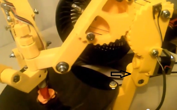
The Spectra line always runs across the smooth part of the M8 bolts. When they're installed in the arms, there is a nylon lock-nut threaded backwards onto the bolt (with the nylon insert towards the bolt head) and another one right-way around to hold it on the outside of the arm. That isn't visible in the snapshot you took from the video, but I can take a picture later to show the detail. Having the head outside the arm is a feature, not a bug; it makes stringing the arms much easier. I'm not sure how to explain that without you being able to see it for yourself, but perhaps I can put together a video of the stringing process (though my video skills are weak at best).
The Spectra crosses the bolts very near the attachment point, so the torque against the attachment point to the arm is minimal. The holes are sized to have a tight fit on the nylon locknuts; it takes a bit of fiddling to get the bolts into position, and they're extremely solid once the second nut is tightened down. The extra boss on the outside gives the arm enough thickness that the outside nut is tight with at most a thread showing. And even on my arms, which were printed using another machine that had a fussy extruder and was laying down quite a few layers with too little filament, the bolts are solid. That said, releasing the tension on the arms if the machine is going to be parked for a long time is certainly a good idea. That's a good idea for guitars, too, and luckily we have a guitar tuning machine, which makes it easy
I'm not sure that we care a great deal about repeatability a continuous 72 hour test; I have yet to see a print take that long. Obviously we *do* care about repeatability for the sake of calibration and bed leveling. I think that one of the lessons we've already learned is a need for some kind of auto-leveling capability, either a mechanical probe as some of the three-tower deltas use, or something perhaps a little different; Nicholas has some ideas there.
The current endstops have a couple of flaws. I found them difficult to adjust; the trick is to rotate an eccentric cylinder that's held by an M3 screw so that it actuates the microswitch at the appropriate moment. But of course tightening the screw makes the cylinder want to move I ended up gluing one adjuster in place because it was so finicky, though that wasn't so bad because that arm became my reference, and the others were adjusted to match it. I can't quite work out in my head whether the geometry at the shoulder joint would be better or worse; visualizing things like that has always been difficult for me, I need to hold something in my hands. It looks as though it would be easier to design an endstop with a screw adjustment at that position, but it would also put the endstop and switch more in harm's way for accidental contact with other things on the table nearby. As it is, it's too easy to snag the lever on the switch when working around the machine. Unfortunately this design needs adjustability and can't use Wally's simple mechanical stops.
@A2: I can respond to some of those questions/observations based on the few days of testing we've had so far.
The Spectra line always runs across the smooth part of the M8 bolts. When they're installed in the arms, there is a nylon lock-nut threaded backwards onto the bolt (with the nylon insert towards the bolt head) and another one right-way around to hold it on the outside of the arm. That isn't visible in the snapshot you took from the video, but I can take a picture later to show the detail. Having the head outside the arm is a feature, not a bug; it makes stringing the arms much easier. I'm not sure how to explain that without you being able to see it for yourself, but perhaps I can put together a video of the stringing process (though my video skills are weak at best).
The Spectra crosses the bolts very near the attachment point, so the torque against the attachment point to the arm is minimal. The holes are sized to have a tight fit on the nylon locknuts; it takes a bit of fiddling to get the bolts into position, and they're extremely solid once the second nut is tightened down. The extra boss on the outside gives the arm enough thickness that the outside nut is tight with at most a thread showing. And even on my arms, which were printed using another machine that had a fussy extruder and was laying down quite a few layers with too little filament, the bolts are solid. That said, releasing the tension on the arms if the machine is going to be parked for a long time is certainly a good idea. That's a good idea for guitars, too, and luckily we have a guitar tuning machine, which makes it easy
I'm not sure that we care a great deal about repeatability a continuous 72 hour test; I have yet to see a print take that long. Obviously we *do* care about repeatability for the sake of calibration and bed leveling. I think that one of the lessons we've already learned is a need for some kind of auto-leveling capability, either a mechanical probe as some of the three-tower deltas use, or something perhaps a little different; Nicholas has some ideas there.
The current endstops have a couple of flaws. I found them difficult to adjust; the trick is to rotate an eccentric cylinder that's held by an M3 screw so that it actuates the microswitch at the appropriate moment. But of course tightening the screw makes the cylinder want to move
I ended up gluing one adjuster in place because it was so finicky, though that wasn't so bad because that arm became my reference, and the others were adjusted to match it. I can't quite work out in my head whether the geometry at the shoulder joint would be better or worse; visualizing things like that has always been difficult for me, I need to hold something in my hands. It looks as though it would be easier to design an endstop with a screw adjustment at that position, but it would also put the endstop and switch more in harm's way for accidental contact with other things on the table nearby. As it is, it's too easy to snag the lever on the switch when working around the machine. Unfortunately this design needs adjustability and can't use Wally's simple mechanical stops.
|
Re: New arm design for Simpson style printer. October 06, 2013 02:07AM |
Registered: 10 years ago Posts: 31 |
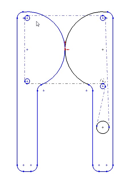
I don't know precisely how the Simpson is strung, so perhaps this analysis needs to be updated. Let me know.
What I wanted to investigate was what the effect would be if the string were run over pulleys instead of just sliding on the bolts.
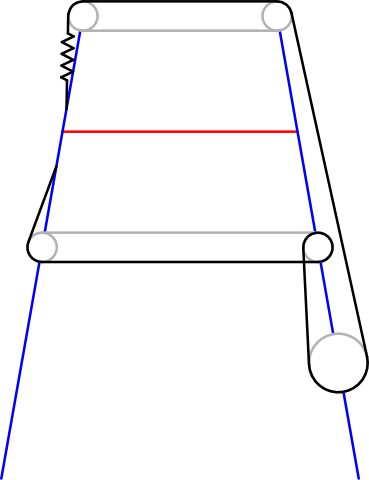
This geometric mock-up lets you change the pulley sizes and all the dimensions, and then look at the total string length as the elbow angle alpha is varied.
One thing I learned is that the string length is not constant in this arrangement unless the string ends terminate on the same arm as the motor. When the pulley diameter is small, like the bolt diameter, the error is small but not zero. So the spring and the guitar peg have to be on the motor's arm.
This design has the string in red, and assumes that whenever the string seems to touch a pulley a second or third time, there are really 2 or 3 pulleys on the same axle.
The X1 assumes the string just passes from the motor arm to the other and is terminated there. X2 has it go around the pulley on the second arm and return to be terminated at the first. X3 crosses a third time, and X4 a fourth (mechanical advantage of 4). The termination locations were chosen to be unaffected by the normal range of angles, and are not (and don't need to be) realistic.
To view and play with the model, use this link: (It runs in your browser, using javascript or optionally java.)
[www.geogebratube.org]
BTW, GeoGebra is a wonderful tool, and it's free. I was unable to do this work in Mathematica (too complicated), but it was dead simple in GeoGebra, which I'd never even heard of before. GeoGebra includes Reduce, a serious computer package for symbolic algebra and calculus. A 3D version is in beta.
Dave
What I wanted to investigate was what the effect would be if the string were run over pulleys instead of just sliding on the bolts.
This geometric mock-up lets you change the pulley sizes and all the dimensions, and then look at the total string length as the elbow angle alpha is varied.
One thing I learned is that the string length is not constant in this arrangement unless the string ends terminate on the same arm as the motor. When the pulley diameter is small, like the bolt diameter, the error is small but not zero. So the spring and the guitar peg have to be on the motor's arm.
This design has the string in red, and assumes that whenever the string seems to touch a pulley a second or third time, there are really 2 or 3 pulleys on the same axle.
The X1 assumes the string just passes from the motor arm to the other and is terminated there. X2 has it go around the pulley on the second arm and return to be terminated at the first. X3 crosses a third time, and X4 a fourth (mechanical advantage of 4). The termination locations were chosen to be unaffected by the normal range of angles, and are not (and don't need to be) realistic.
To view and play with the model, use this link: (It runs in your browser, using javascript or optionally java.)
[www.geogebratube.org]
BTW, GeoGebra is a wonderful tool, and it's free. I was unable to do this work in Mathematica (too complicated), but it was dead simple in GeoGebra, which I'd never even heard of before. GeoGebra includes Reduce, a serious computer package for symbolic algebra and calculus. A 3D version is in beta.
Dave
|
Re: New arm design for Simpson style printer. October 06, 2013 03:53PM |
Registered: 10 years ago Posts: 979 |
@DaveGadgeteer: That is super sweet! The only thing that I do different is that the string wraps counter-clockwise around the bottom two bolts. I vaguely remember doing the math back when I went for the slave arm mounting of the tuner. I honestly can't remember if the length was constant or not. (Knowing myself, I would allow myself to do that mounting even if there is a small deviation in string length as long as the spring can buffer it.) I will re-look at it to make sure. Everything can be squeezed onto the motor arm but it will make stringing just a bit harder.
Thanks again for a great tool!
Edited 1 time(s). Last edit at 10/06/2013 06:05PM by nicholas.seward.
Thanks again for a great tool!
Edited 1 time(s). Last edit at 10/06/2013 06:05PM by nicholas.seward.
|
Re: New arm design for Simpson style printer. October 06, 2013 04:10PM |
Registered: 10 years ago Posts: 979 |
@DaveGadgeteer: I just looked at it again and all my memories on the subject came flooding back. With the clock-wise wrapping change on the bottom bolt you will have a constant string length. However, there is one catch. You will destroy the proportionality of the drive unit. Meaning, the distance the arm ends are apart is not a simple proportional function of the drive pulley's rotation. (This is for the tuning peg being on the slave arm. Everything is perfect with everything on the motor arm.) However, however, for 8mm bolts it is a small effect and it gets reduced further based on the number of wraps you do.
|
Re: New arm design for Simpson style printer. October 07, 2013 10:15AM |
Registered: 10 years ago Posts: 14 |
|
Re: New arm design for Simpson style printer. October 07, 2013 11:53AM |
Registered: 10 years ago Posts: 979 |

|
Re: New arm design for Simpson style printer. October 08, 2013 09:43PM |
Registered: 10 years ago Posts: 1,381 |


Routing:
You could add two additional pins to the lower pulley/pivots as a workaround to the 1.5 wrap.
Or:
I like the idea of small ceramic pulleys riding steel shafts.
Ceramic fishing eyes might be a cheap option in bulk.
Note: there is an OD grove on the ceramic fishing guides that the metal snaps into.
The line would run in this grove.
I don't understand the use of the spring, or it's placement in the system.
A close up picture of the spring and the tensioner would help.
A few pics to generate ideas.
A2
Edited 3 time(s). Last edit at 10/08/2013 09:53PM by A2.
Attachments:
open | download - ScreenHunter_159 Oct. 08 21.32.jpg (12.3 KB)
open | download - ScreenHunter_160 Oct. 08 21.33.jpg (11.4 KB)
open | download - ScreenHunter_161 Oct. 08 21.33.jpg (10.3 KB)
open | download - ScreenHunter_162 Oct. 08 21.33.jpg (10 KB)
open | download - ScreenHunter_163 Oct. 08 21.34.jpg (31 KB)
open | download - ScreenHunter_164 Oct. 08 21.34.jpg (26.8 KB)
|
Re: New arm design for Simpson style printer. October 09, 2013 07:51AM |
Registered: 10 years ago Posts: 1,381 |

Routing:
Shift the lower pulley down an amount equal to it's diameter.
This arrangement is equivalent to the upper pulley mechanical advantage.
Eliminates the 1.5 wrap, and associated issues.
A2
Edited 1 time(s). Last edit at 10/09/2013 07:51AM by A2.
|
Re: New arm design for Simpson style printer. October 09, 2013 08:46AM |
Registered: 15 years ago Posts: 401 |
@A2,
How hard is it, in software, to compensate for the behaviour you are trying to eliminate? If it's easy to compensate, just roll it into the inverse kinematics.
The overriding principle of designing new geometries of 3D printer is: pick the best geometry to fit [insert goal here]. If this doesn't match cartesian geometry, compensate in software. This is no different.
While the solution you propose looks good for a single wrap, it will cause problems for more than one wrap. Simpson contains an optional force multiplier: the block/tackle arrangement.
For an integral number of wraps, the total length of the cable on one side is: n*(c + 2d) where n is the number of wraps, c is the circumference of the pulleys, and d is the separation between pulley centres.
For a wrapping scheme that includes a half-wrap, the total length of the cable on one side is: n*(2*pi*r + 2d) + d + 2ra, where n is the number of complete wraps, r is the radius of the pulley, d is the separation between pulley centres, and a is the angle between the arm and the line that is drawn through two pulleys on opposite arms.
A key point here is that the sum of the lengths of both the top and bottom strings never changes. As Nick has mentioned before, the more wraps you do, the less the 2ra term matters.
However, for the pedantic among us, here's what you need to calculate the angle of the arm with respect to the active region of the string (the line between the two pulleys).
a = arccos(dg-d/(2r))
dg is the separation between the two gear centres. d is the separation between the pulleys. r is the distance from the gear centre to a pulley.
If a is calculated for the bottom pulley, -a is the value for the top pulley.
While this could be fixed with an integral number of wraps, it's not horrible.
|
Re: New arm design for Simpson style printer. October 09, 2013 10:12AM |
Registered: 10 years ago Posts: 1,381 |
With the bottom pulley offset the line length is equal on both sides of the equation.
You can add loops to the offset pulley just as Nicholas has in his schematic. If you apply loops equally to both the top and bottom pulleys the line remains equal in length.
I'm not understanding how a loop corrects for non-linearity. Please point me to a scholarly paper that will help me understand the magic of loops
Test:
If loops make a significant contribution to correcting non-linearity, then this can be quantified with a dial test indicator, and/or measure a test part.
I have not seen the software and the associated maths, I would like to see a snippet of the code in question with an explanation of what I'm looking at.
Question:
What is the maximum included angle between adjacent arms when fully extended?
Maybe a beta tester can measure this.
A2
|
Re: New arm design for Simpson style printer. October 09, 2013 10:26AM |
Registered: 10 years ago Posts: 979 |
Real quick: The non-linearity is destroyed because the amount of string in contact with the bolts change for the first and last interface. (routing artifacts) All the intermediate interfaces have a constant amount of string. (180 degrees) The question is how big is the change in the routing artifacts vs the change in the overall length of string (for one side). As you can see, the routing artifacts will not grow larger as you loop more times. Theoretically, we just have to loop an infinite number of time. :-) (or we can put the tuner and the spring back on the motor arm but that is hard to do in an elegant way.)
length of string on one side=n*(2*pi*r + 2d) + d + 2ra
As n increases the 2ra term become less significant.
Edited 1 time(s). Last edit at 10/09/2013 11:54AM by nicholas.seward.
length of string on one side=n*(2*pi*r + 2d) + d + 2ra
As n increases the 2ra term become less significant.
Edited 1 time(s). Last edit at 10/09/2013 11:54AM by nicholas.seward.
|
Re: New arm design for Simpson style printer. October 09, 2013 11:24AM |
Registered: 11 years ago Posts: 58 |
A2 Wrote:
> Question:
> What is the maximum included angle between
> adjacent arms when fully extended?
> Maybe a beta tester can measure this.
If you mean the angle between two halves of the same arm, they can happily go straight (running right over the endstop switch) if you ask them to. You should not do that, however
|
Re: New arm design for Simpson style printer. October 09, 2013 11:43AM |
Registered: 15 years ago Posts: 401 |
A2 Wrote:
-------------------------------------------------------
> I'm not understanding how a loop corrects for
> non-linearity. Please point me to a scholarly
> paper that will help me understand the magic of
> loops
The magic of loops:
But seriously, it's a geometry question. As long as you perform complete loops, the total engagement of the cable on any pulley remains equal. With the half-loops, the engagement length changes with arm angle, per the formula I provided. If you can disprove my formula, I'm happy to take another look at it.
|
Re: New arm design for Simpson style printer. October 09, 2013 01:46PM |
Registered: 10 years ago Posts: 1,381 |

“As long as you perform complete loops, the total engagement of the cable on any pulley remains equal. With the half-loops, the engagement length changes with arm angle, per the formula I provided.”
Problem:
The inability to wrap a whole (integer) number of loops around a pulley (e.g. 2 loops).
Instead you can only achieve a fractional number of loops around a pulley (e.g. 1.5 loops).
The string coming off of the stepper motor drum is at 90 degrees to the pulley.
Solution:
To obtain whole number of loops around the pulley, add another pulley to reroute the string into a position that is inline to the direction that you want to pull in. This allows the start, and end location of the loops to be located at the same position on the pulley.
A2
Edited 1 time(s). Last edit at 10/09/2013 01:46PM by A2.
|
Re: New arm design for Simpson style printer. October 09, 2013 02:46PM |
Registered: 15 years ago Posts: 401 |
@A2: it took me a bit to figure out what was bothering me about your suggestions of additional or asymmetric pulleys. Here it is: the simplicity of the Simpson geometry comes from symmetry. As soon as you break the symmetry, the math falls apart and gets really complex. Your latest suggestion is asymmetric. Because of this, it's much more complex to work out the kinematics. If you think n*(2*pi*r + 2d) + d + 2ra is bad, I wouldn't recommend trying offset pulleys.
|
Re: New arm design for Simpson style printer. October 09, 2013 06:03PM |
Registered: 10 years ago Posts: 979 |
Okay, here comes a "thank goodness for the forum" and a "face palm" moment all wrapped in one.
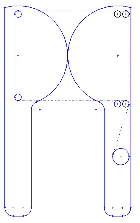
So my assumption was that after calibrating the min and max actuated distance of each arm using the simplified equations that assume the bolts have r=0 that I would be so close that I wouldn't have to worry about the bolt diameter.
As you can see from the graph that I was off as much as .4mm. While 400 microns isn't a whole lot it should still be accounted for. You can see on the graph that when I go to 2.5 wraps like I plan to do it should bring the max error down to 230 microns. However, math is cheap. I will now start adjusting for the bolt diameter. (If you are wondering why I even thought it was okay to exclude that term in the first place, it is because great care will have to be taken to make sure I get this second order adjustment right. It would be all too easy to have a flipped sign and never know it.)
I will also revisit putting the tuning peg and the spring on the motor arm. In that case, the length of string in contact with a bolt on each side will be a constant.
Edited 2 time(s). Last edit at 10/09/2013 06:04PM by nicholas.seward.
So my assumption was that after calibrating the min and max actuated distance of each arm using the simplified equations that assume the bolts have r=0 that I would be so close that I wouldn't have to worry about the bolt diameter.

As you can see from the graph that I was off as much as .4mm. While 400 microns isn't a whole lot it should still be accounted for. You can see on the graph that when I go to 2.5 wraps like I plan to do it should bring the max error down to 230 microns. However, math is cheap. I will now start adjusting for the bolt diameter. (If you are wondering why I even thought it was okay to exclude that term in the first place, it is because great care will have to be taken to make sure I get this second order adjustment right. It would be all too easy to have a flipped sign and never know it.)
I will also revisit putting the tuning peg and the spring on the motor arm. In that case, the length of string in contact with a bolt on each side will be a constant.
Edited 2 time(s). Last edit at 10/09/2013 06:04PM by nicholas.seward.
|
Re: New arm design for Simpson style printer. October 09, 2013 10:51PM |
Registered: 10 years ago Posts: 1,381 |

I don't want any error
So I'll keep at it.
Idea:
Center the drum between the two symmetrical pulley systems, and tangential to the string coming off of the pulleys. This arrangement allows for magic loops
The tensioner is located opposite the drum on the opposing arm, but could be located on, or within the drum.
Smallest O.D. of the pulley = Dia 0.02” x 8 = 0.16” (4.0 mm).
A2
Edited 1 time(s). Last edit at 10/09/2013 10:52PM by A2.
|
Re: New arm design for Simpson style printer. October 09, 2013 11:12PM |
Registered: 10 years ago Posts: 979 |
@A2: This arrangement is equivalent to how GUS Simpson is currently strung which deviates from the proportional response we want due to the varying amount of string in contact with a bolt on each side of the system.
So there isn't really any error. If we put the tuner on the slave arm, we have to put an adjustment term in the equations as Annirak shows above to adjust for the amount of string in contact with the bolts on each side. If we put the tuner on the motor arm, we have a perfect proportional response. The question is where to put the tuner and the spring on the motor arm.
So there isn't really any error. If we put the tuner on the slave arm, we have to put an adjustment term in the equations as Annirak shows above to adjust for the amount of string in contact with the bolts on each side. If we put the tuner on the motor arm, we have a perfect proportional response. The question is where to put the tuner and the spring on the motor arm.
|
Re: New arm design for Simpson style printer. October 09, 2013 11:29PM |
Registered: 10 years ago Posts: 1,381 |

“If we put the tuner on the motor arm, we have a perfect proportional response. The question is where to put the tuner and the spring on the motor arm.”
Fantastic!
OK, I'll integrate the tuner into the drum, give me a few minutes to work out a mechanism j/k
What is the spring for, safety, or some thing else?
What is the maximum OD of the drum allowed before we loose all our torque?
How long is the drum?
I believe that the shaft OD of a NEMA 17 is .200 inch?
Any other dimensions I need please post.
A2
Edited 1 time(s). Last edit at 10/09/2013 11:29PM by A2.
|
Re: New arm design for Simpson style printer. October 10, 2013 12:03AM |
Registered: 10 years ago Posts: 979 |
@A2:
What is the spring for, safety, or some thing else?
The spring is designed so that as the imperfect gears roll across each other and there are minute changes in total string length that the tension doesn't wildly vary or worse yet cause binding. Currently, I use the tuner to extend the spring until it almost touches the M8 bolt. I designed it so that the spring puts 3.5+lbf of tension into the string at that point. That doesn't sound like much tension but multiply that by each string that goes between the two sides and you get around 20lbf pushing the gears together. (Without a spring I suspect the force between the sides would vary between 0 and 100lbf.)
What is the maximum OD of the drum allowed before we loose all our torque?
Any OD will do. The steppers (60oz-in rated holding torque) I use can safely produce 40oz-in over the whole operational range. That combined with the number of wraps that you do, max design acceleration, hub mass, arm mass, usuable print volume, and whatever else I can think of will help determine the size of the pulley. I am personally going to go with a 15mm pulley with 2-3 wraps. (In that case, the steppers are about 8 times more powerful than they need to be if we had frictionless bolts. For reference, the steppers are currently about 3 times more powerful than they need to be with frictionless bolts but are right on the edge when you operate in a dusty environment like the NY Maker Faire.)
How long is the drum?
Long enough to store the length of the string that can be transferred from one side of this system to the other side plus a health margin.
I believe that the shaft OD of a NEMA 17 is .200 inch?
The first couple of NEMA17 spec sheets I looked at specify the shaft OD as 5mm nominal and 5.000mm-4.988mm actual. Which is very close to .2" but not close enough to call it the same thing.
Any other dimensions I need please post.
Dimensions aren't really important. The beauty of Simpson and the PGDJ is that it isn't one particular thing. It is a whole family of things. We just have to line out basic geometry and the best practices and the individual bot builders will pick values that will work for their particular project.
Edited 1 time(s). Last edit at 10/10/2013 12:05AM by nicholas.seward.
|
Re: New arm design for Simpson style printer. October 10, 2013 12:05AM |
Registered: 10 years ago Posts: 1,381 |

Idea:
Use a split drum, i.e. two drums mounted onto the shaft of the stepper motor.
This will allow you to adjust the tension at the drum by counter rotating one or both of the drums, then lock the drum down with a set screw to maintain tension.
Place a spanner wrench into the face of the drum and apply tension, then lock the drum down with a set screw.
With this system you can use one continuous string or two.
Are you using steppers with flats on the shaft?
A2
Edited 1 time(s). Last edit at 10/10/2013 12:05AM by A2.
|
Re: New arm design for Simpson style printer. October 10, 2013 12:10AM |
Registered: 10 years ago Posts: 979 |
@A2: The split drum would work if you used a torsion spring but the design for such a drum doesn't jump immediately to my mind. The single extension spring is a pretty cheap easy solution.
Most NEMA17 steppers have a flat. Mine also have flats.
This is what I believe to be the most common configuration for RepRap steppers.
Most NEMA17 steppers have a flat. Mine also have flats.
This is what I believe to be the most common configuration for RepRap steppers.

|
Re: New arm design for Simpson style printer. October 10, 2013 12:32AM |
Registered: 10 years ago Posts: 1,381 |

Spring:
I understand the gear binding issue and the need for the spring.
I have not seen a picture of the spring, it's placement in the system, or it in action, and can not comment on the virtues of a torsion vs. a coil spring relative to the use of a split drum tensioner, or how the difference between the two spring types rule out my design suggestion.
Is the dual independent drum tensioner idea dead, alive, or do you need more info, I don't understand what issue you are addressing.
A2
Edited 1 time(s). Last edit at 10/10/2013 12:33AM by A2.
|
Re: New arm design for Simpson style printer. October 10, 2013 01:06AM |
Registered: 10 years ago Posts: 979 |

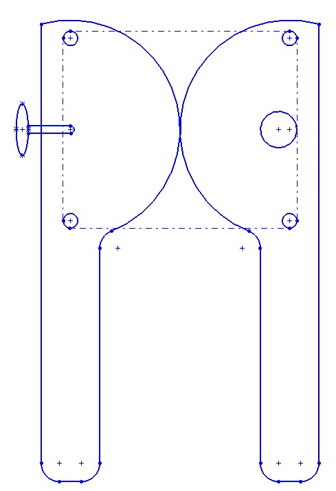
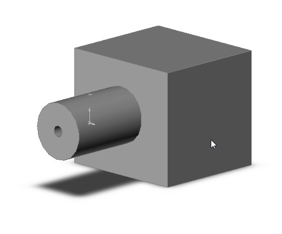
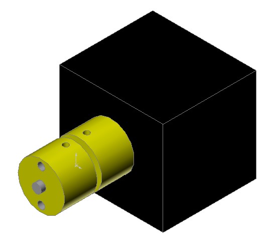
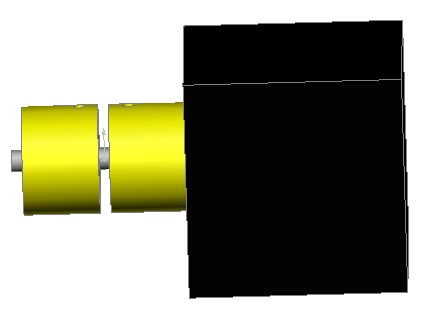
This isn't a high res image or the perfect angle but it should help a little bit for people like me that need to visualize. You can see a hint of the spring in through the gothic arch like opening in the upper right of the image.
@A2: There is nothing wrong with the dual drum tensioner. Before you design it I have to ask what end purpose does it serve? Does it take slack out of the system? (Like the guitar tuning peg.) Does it provide a near constant string tension? (Like the spring.) Does it do both?
To do both you would need a torsion spring and a ratchet in the split drum. You would need some way to adjust the spring tension to the optimal torque while you take the slack out of the spring. That is not a problem just design.
It goes without saying that you could do the ratchet or the spring by itself in the split drum design.
What I don't think will work is having neither a ratchet or a torsion spring in the drum. (or their equivalents) In that situation, you will be able to remove the slack in the system for just small periods of time but won't be able to produce a predictable maintainable force in the string.
Note: I have fallen in love with the tuners. It allows me to detension the system quickly and retension right before I run the machine. I am sure this will extend the life of the string just like it does for archery bows and for violin bows. Additionally, I find myself continually adjusting the tension. Whatever mechanism we use for tension adjustment, it has to be quick and easy.
For the record: I know how to put everything on the motor arm. I should make a drawing if I can find the time. The problem is clutter and the ease of restringing. IMHO the number 1 thing that will hurt GUS Simpson is going to be the time and focus it takes to restring an arm. (If I have to do harder math in the software to make restringing easier then I will do harder math.) It gets much easier after you have done it 6-9 times but I doubt most people will want to stick with it that long. The tuner and the spring on the slave arm as I have shown above makes for a cleaner routing that is easier to understand. Even if you have a split drum, (I am interested in this idea.) you still have to tie the two ends off which boils down to practically the same problem as where do I put the tuner and the spring.
|
Re: New arm design for Simpson style printer. October 10, 2013 02:30AM |
Registered: 10 years ago Posts: 31 |
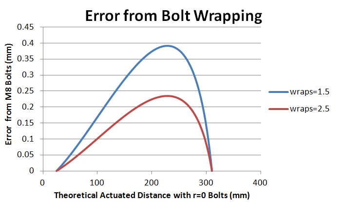
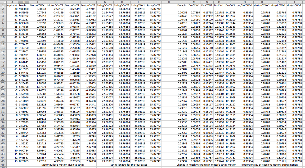
I cleaned up my GeoGebra model and collected data in a spreadsheet for proportionality and string length variation over a fairly large range of elbow angles.
There's a screen shot attached. And the spreadsheet in Excel form. And I'll post the GeoGebra working model as before, and am attaching its file here for those who have installed (free) GeoGebra and would like to modify and exercise the model.
The website working model is at
[www.geogebratube.org]
It was tedious getting it cleaned up, and the model machinery seems needlessly complex, because there seems to be no reliable tangent line segment, so I have to use hidden lines that are tangent except in rare cases of roundoff error, cross them with perpendicular lines, define the intersection point (which is now reliably existing), then put my visible segments between those points. So there are a lot of extra names corresponding to hidden lines. (This is only relevant for those of you who are going to modify the model.)
It's also more complicated because the lower pulleys are handling both cases, CW (bluish string shows in places) and CCW (red strings, my original model). The CW model is lovely, and works perfectly for all multipliers. Clever, Nick!!
(Explanation to others: It's the wraps to the anchor points that vary with angle, and have to be compensated by appropriate geometry.)
There's one limitation built into this model. It assumes the pulleys are larger than the motor pulley, so that the Opening string that goes to the upper pulleys is deflected as it passes the lower pulley. It's easy to change this, but trickier to make it adapt conditionally, and since I wasn't interested in that case (I was wondering about using nice pulleys instead of sliding on bolts) I didn't worry about it.
Other than that, all distances and diameters are adjustable with sliders.
|
Re: New arm design for Simpson style printer. October 10, 2013 02:40AM |
Registered: 10 years ago Posts: 31 |
It's a pity that the proportionality (dm/dr) suffers on the CWx1 model (as shown in spreadsheet).
But as long as you take an even multiplier, either CW or CCW on the lower pulleys works fine, string lengths are constant and proportionality is great.
So, moving the tuner to the motor arm does have a payoff that's probably worth the mess/trouble.
I forgot about the proportionality failure in my previous message, was just looking for constant string length.
Dave
|
Re: New arm design for Simpson style printer. October 10, 2013 03:52AM |
Registered: 10 years ago Posts: 1,381 |


Guitar tuner:
“If we put the tuner on the motor arm, we have a perfect proportional response.”
I need some clarity again
By integrating the tensioner (guitar tuner) into the dual drum the nonlinearity error of 400 to 230 microns (.016” to .009”) is eliminated, is this correct? Or are you saying mount the guitar tuner on the same arm as the stepper motor will eliminate the nonlinearity. I think I miss read what you meant earlier.
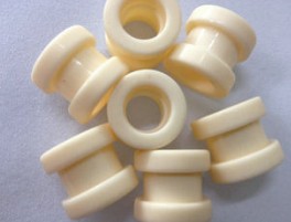
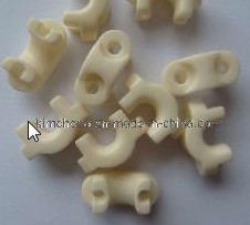
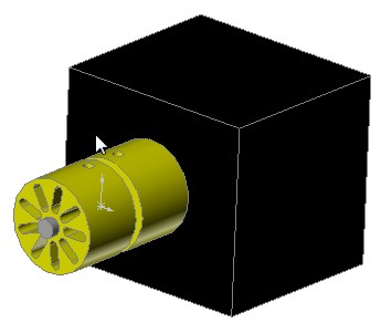
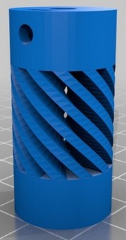
Dual drum purpose:
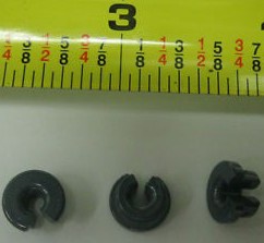
To eliminate the nonlinearity, and to take the slack out of the system; it's a replacement to the guitar tuner. Possibly a spring like buffer could also be integrated into the drum without increasing the vitamin count if a semi-resilient material was used, with a fluted core, see attached pictures.
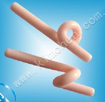
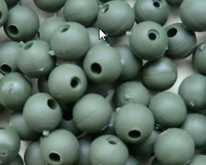
Rubber shock beads (spring):
Another trick is to loop the string through a resilient bead, this acts as a spring. Providing there is room for the bead to move back and forth between two pulleys it will work as a spring absorbing shock. Add additional beads to increase the amount of stretch.
Street appeal:
For me restringing the arms is a non issue. But friends have said that the string is a bit confusing in their mind. Making the math work is probably the way to go for the average consumer.
A2
Edited 1 time(s). Last edit at 10/10/2013 03:54AM by A2.


Sorry, only registered users may post in this forum.