New arm design for Simpson style printer.
Posted by Guizmo
|
Re: New arm design for Simpson style printer. August 16, 2013 03:11PM |
Registered: 12 years ago Posts: 85 |
|
Re: New arm design for Simpson style printer. August 16, 2013 03:48PM |
Registered: 10 years ago Posts: 145 |
|
Re: New arm design for Simpson style printer. August 16, 2013 03:59PM |
Registered: 11 years ago Posts: 979 |
For a standard Simpson it is potentially bad. It could possibly destroy the hot end and a few plastic pieces. However, if you turned gravity around the failure would be no big deal. For a 1 arm SCARA design that Quentin Harley and I are contemplating, the failure would also be no big deal. When I get this going I will try to get an estimate for the cycles to failure. I can then give a recommendation as to how often you need to change out strings.
|
Re: New arm design for Simpson style printer. August 16, 2013 05:41PM |
Registered: 11 years ago Posts: 58 |
Thinking about the guitar tuning machines - they're designed for two things, to be able to adjust the string tension very precisely, and to hold the tension without any kind of mechanical lock. We don't need either characteristic: if there's a spring on the other end, all we need is to get some extension of the spring, and we can use a mechanical lock. Release the lock to adjust the tension, observe the spring for the right extension, then lock it down again. It probably wouldn't even be necessary to have mechanical advantage to put 5 lbs tension on the string, though it might be nicer on your hands 
I can think of a couple of ways to implement that. Something that looks more like a violin tuning peg could work along with the locking bar you already have (shortened, because only one side of the string will be locked, the other will go to the spring). Or a lever that allowed you to pull the loose string until it was taut, then hold the string, and move the lever a little further with a screw to add the extra tension. Or probably ten other things, none of which require tuning machines. . .
I can think of a couple of ways to implement that. Something that looks more like a violin tuning peg could work along with the locking bar you already have (shortened, because only one side of the string will be locked, the other will go to the spring). Or a lever that allowed you to pull the loose string until it was taut, then hold the string, and move the lever a little further with a screw to add the extra tension. Or probably ten other things, none of which require tuning machines. . .
|
Re: New arm design for Simpson style printer. August 16, 2013 06:43PM |
Registered: 11 years ago Posts: 979 |
|
Re: New arm design for Simpson style printer. August 16, 2013 06:58PM |
Registered: 10 years ago Posts: 14 |
A ratcheted crank/knob, maybe based on something like [www.thingiverse.com] would be printable (albeit, I'd think you'd want ABS and not PLA), and could serve a similar purpose, especially with a spring to grant additional elasticity to the pulley.
I suppose it really depends on your goal. A mass manufactured tuning peg is likely to be cheaper, more reliable, and slightly easier to use. Plastic could be made lighter, could possibly be integrated into the printed arm, and isn't a vitamin.
Edit: Or maybe do a ratchet the other way around: put the teeth on the outside (a shaped hole integrated into the design of the arm), and print the flexing part of the ratchet on a peg in ABS that can be stuck into the hole. Once tensioned, the tension should be enough to keep the tuning "peg" from moving too much.
Edited 7 time(s). Last edit at 08/16/2013 07:16PM by Shawn.Walker.
|
Re: New arm design for Simpson style printer. August 16, 2013 07:22PM |
Registered: 11 years ago Posts: 979 |
|
Re: New arm design for Simpson style printer. August 16, 2013 08:19PM |
Registered: 10 years ago Posts: 14 |
[www.mcmaster.com] :
Or maybe an L-shaped hex key. These are pretty cheap, too, and you can get them anywhere. [www.mcmaster.com] :
Edit: Unless I'm mistaken, there's no significant need for this shaft to be completely round -- it's not intended to move often.
Edited 5 time(s). Last edit at 08/16/2013 08:36PM by Shawn.Walker.

Or maybe an L-shaped hex key. These are pretty cheap, too, and you can get them anywhere. [www.mcmaster.com] :

Edit: Unless I'm mistaken, there's no significant need for this shaft to be completely round -- it's not intended to move often.
Edited 5 time(s). Last edit at 08/16/2013 08:36PM by Shawn.Walker.
|
Re: New arm design for Simpson style printer. August 16, 2013 08:21PM |
Registered: 11 years ago Posts: 58 |
Like this? [www.ebay.com]
|
Re: New arm design for Simpson style printer. August 16, 2013 08:26PM |
Registered: 10 years ago Posts: 14 |
|
Re: New arm design for Simpson style printer. August 16, 2013 08:52PM |
Registered: 11 years ago Posts: 58 |
Hmm, you're right - that doesn't look like the right picture, it's obviously zinc plated and the auction is for stainless. But I've bought socket head bolts from those folks before, and all of the longer M3 ones have only partial threading. I'll email them and ask.
Edit: Yep, that's a dead end, all their M3 bolts are fully threaded.
Edited 1 time(s). Last edit at 08/16/2013 09:21PM by owens.
Edit: Yep, that's a dead end, all their M3 bolts are fully threaded.
Edited 1 time(s). Last edit at 08/16/2013 09:21PM by owens.
|
Re: New arm design for Simpson style printer. August 17, 2013 12:52AM |
Admin Registered: 13 years ago Posts: 730 |
|
Re: New arm design for Simpson style printer. August 17, 2013 02:18AM |
Registered: 11 years ago Posts: 979 |
|
Re: New arm design for Simpson style printer. August 17, 2013 09:43AM |
Registered: 10 years ago Posts: 1,381 |
@Nicholas,
Zip tie looks OK, but I don't like the idea of tugging against the device to tighten it.
A SHCS, and nut with a hole through the head of the screw.
Turn the screw to take up the slack, then lock it down with the nut.
I like the SHCS because I can easily adjust it if I felt it needed inspecting.
An eccentric cam.
A leaf spring, low profile, light weight, high force.
You could also attach the string to a cam, which would push on a coil spring to increase the rate of force.
A2
|
Re: New arm design for Simpson style printer. August 17, 2013 11:36AM |
Registered: 10 years ago Posts: 23 |
Carbon fiber string. Possible ?
[youtu.be]
nicholas.seward Wrote:
-------------------------------------------------------
> For a standard Simpson it is potentially bad. It
> could possibly destroy the hot end and a few
> plastic pieces. However, if you turned gravity
> around the failure would be no big deal. For a 1
> arm SCARA design that Quentin Harley and I are
> contemplating, the failure would also be no big
> deal. When I get this going I will try to get an
> estimate for the cycles to failure. I can then
> give a recommendation as to how often you need to
> change out strings.
Updated: I agreed about Kevlar braid. And sorry I seem to distracted this thread a bit.
Anyway, Kamermaker use shipping container. Maybe we can design a float raft for leveling a very scalable platform and able to print a whole building while SLS can't.
Edited 1 time(s). Last edit at 08/17/2013 02:42PM by Buytaert.
|
Re: New arm design for Simpson style printer. August 17, 2013 12:28PM |
Registered: 11 years ago Posts: 979 |
@A2: I would prefer not to drill into the head of a SHCS. Can you give me more info on how you see the leaf spring working? And the cam? I want the setup to be stupid simple.
@Buytaert: I would have to test this but I think carbon fiber is stronger than spectra but would not be as good in terms of cycles per failure. Do you have a source for a braided line that would be appropriate for a test? I have also considered Kevlar. BTW, we are looking at spear gun line for a 16 foot tall Simpson.
@Buytaert: I would have to test this but I think carbon fiber is stronger than spectra but would not be as good in terms of cycles per failure. Do you have a source for a braided line that would be appropriate for a test? I have also considered Kevlar. BTW, we are looking at spear gun line for a 16 foot tall Simpson.
|
Re: New arm design for Simpson style printer. August 17, 2013 12:46PM |
Registered: 10 years ago Posts: 1,381 |
|
Re: New arm design for Simpson style printer. August 17, 2013 02:06PM |
Registered: 10 years ago Posts: 1,381 |
@Nicholas,
I didn't think any one would consider building a Simpson this big, I was wrong
I've been designing a 9' 6” long print envelope, which requires about 16' long arms. Clues of it being constructed larger are hidden in the pictures that I posted of the bearingless Simpson
I was attracted to the Simpson platform because I could see that it could easily be scaled up in size, and it doesn't require expensive linear guides. My goal was not the length of the arm, but of the size of the part to be printed. I figured 60% of 16' = 9' 6”, which is roughly how long my part is. For big footprint parts, the cost of linear guides can prevent the project from being cost justifiable. With this inexpensive platform I can now test my ideas.
But where will you put it, and how will you level the bed, lol...?
A2
|
Re: New arm design for Simpson style printer. August 17, 2013 02:20PM |
Registered: 11 years ago Posts: 979 |
Not to derail this thread...but... the current plan is to have a platform for each shoulder that you just stake into the ground. (You can have strings that you stretch tight to get the optimal placement.) At this point you go through a calibration routine over the area that you want to print on. (I am thinking it will be a sheet of MDF laying in the grass.)
If you want to discuss a jumbo Simpson project, let's start another thread. I have definitely been spending some cycles on this. I have some hot ends being made that accept 5mm and output 1.75mm. We have also found a source for 5mm filament in any color for around $10/pound. I think the xDrive is the front runner for the drive mechanism. However, just extending the forearm past the joint to get the right leverage might also be good enough.
If you want to discuss a jumbo Simpson project, let's start another thread. I have definitely been spending some cycles on this. I have some hot ends being made that accept 5mm and output 1.75mm. We have also found a source for 5mm filament in any color for around $10/pound. I think the xDrive is the front runner for the drive mechanism. However, just extending the forearm past the joint to get the right leverage might also be good enough.
|
Re: New arm design for Simpson style printer. August 17, 2013 10:32PM |
Registered: 10 years ago Posts: 14 |
I posted this on the other thread, but I thought I would put it here as well:
I changed my mind about a dozen times, but here is my addition to the project:
[www.youtube.com]
No belts or cables and no odd shaped gears. And this can be simplified even more. You can remove the need for the springs by adding a stopped to the end of the rack gears and then putting them in a sleeve past the arm.
This means the gears would need to be longer (this could be an issue as I think about 280MMs will be the limit), and a very simple bearing could be used.
|
Re: New arm design for Simpson style printer. August 19, 2013 01:18AM |
Registered: 12 years ago Posts: 85 |
|
Re: New arm design for Simpson style printer. August 21, 2013 04:06PM |
Registered: 10 years ago Posts: 145 |
BloodBlight Wrote:
-------------------------------------------------------
> I posted this on the other thread, but I thought I
> would put it here as well:
>
> I changed my mind about a dozen times, but here is
> my addition to the project:
> [www.youtube.com]
>
> No belts or cables and no odd shaped gears. And
> this can be simplified even more. You can remove
> the need for the springs by adding a stopped to
> the end of the rack gears and then putting them in
> a sleeve past the arm.
>
> This means the gears would need to be longer (this
> could be an issue as I think about 280MMs will be
> the limit), and a very simple bearing could be
> used.
Hi,
Could you plase post some images? I have no access to youtube.
Thanks!
|
Re: New arm design for Simpson style printer. August 21, 2013 08:58PM |
Registered: 10 years ago Posts: 14 |
|
Re: New arm design for Simpson style printer. August 22, 2013 10:37AM |
Registered: 10 years ago Posts: 1,381 |


I need to hack a 3D printer together so I can make prototype bearingless Simpson's on the cheap.
3D printer part quote:
This past weekend I got a quote for the upper arm using makeXYZ.com. It was way too expensive for the scope of this project. So I redesigned the arm, and shaved off 90 cm3, and reduced the cost to $45.00, it's probably still too volumetric (fat). Everything needs to be redesigned to reduce unused volume as much as possible. I determined today that shelling is not an option (hollow), shame as there is a massive reduction of part volume. I could get the cost down to $13.00, but impossible to print. Fyi the total cost was $522, not counting electronics, the chunky arms need to slim down
I still have a lot of little details that I need to think about, and make decisions on for the given geometry that I'm working with. I'm excited to work out the varied details, and build a working bearingless Simpson model.
In fill volume cost reduction:
One idea to solve the problem of not being able to print a shelled part is to print 'strategically' placed tiny pins closely spaced, and orientated (some regions of the shelled area would have support others would not have support). Hollow parts need some way to bridge large gaps, and the pins provide that bridging support. Not having a printer I can't test this idea today, but I'm curious what the spacing would be?
The reason a pin is desirable over infill is to get a lower price quote from people who own 3D printers. It appears that the 3D print shops don't care how much material that I'm using, only the volume of the part, shelling reduces the volume thus my cost.
Electrical:
I'm still studying the electronics that work with the Repetier firmware. I like the Azteeg X3, but there are a few others in the same price range that look interesting as well. To reduce my learning curve I want to keep it simple, and the electronics integrated as much as possible. So I'm more interested in the higher end boards (I'm assuming they are easier to get setup and running? i.e. shorter learning curve.). The ARM 32 bit microcontroller appears to be the newest technology, and maybe it's easier to use? I've not run across anyone using ARM with the Repetier firmware (I don't know where to look for examples).
Jumbo Simpson:
I have about 4 pages of notes for a jumbo Simpson 3D printer, with lots of ideas on bed leveling across large spans, etc (FYI I've leveled boring mills to .0005 inch over 10 feet). I've been noodling ideas on this for the past year. But it's not a practical machine for me at this time to begin developing. What I need today is one small desktop printer, and one large printer with about a 1 meter envelope. After I make the two smaller printers, I'll be able to work on my larger product designs, and a larger printer. You should start the thread, as you're already moving it forward.
A2
Edited 3 time(s). Last edit at 08/22/2013 10:53AM by A2.
|
Re: New arm design for Simpson style printer. August 22, 2013 12:17PM |
Registered: 11 years ago Posts: 979 |
That is a shame that the fee model for 3D printing doesn't promote good design. Low infill is vastly superior to shelled parts. I personally design with the simplest part that does the job and throw the volume to the wind. I would propose that you model it the way that you think it should be and then see if you can get a community member to partner up with you on the printing.
Unless you need dual extruders, the Azteeg X1, PrintrBoard, or RAMPS should all be about as easy to use. The more expensive ones will actually add a small layer of complexity. (More possibilities for putting wires in the wrong spot and for setting to get wrong in the firmware.)
I will eventually get around to the Jumbo Simpson. We are also cranking on the a Jumbo Wally. As far as leveling goes, I plan on using software leveling at the time of use. (The Jumbo Simpson I am planning is collapsible so you can easily store it in a corner of a garage meaning leveling has to be redone for each use.) For FDM with a 1.75mm nozzle we only have to get the layer right to +/-1mm. I am sure we can do better than that.
|
Re: New arm design for Simpson style printer. August 22, 2013 03:58PM |
Registered: 10 years ago Posts: 145 |
Those on-line printing services are good, but way expensive. I think they worth the cost only in very special items, such as a silver or gold personalized ring or a very rare material like titanium. For plastic parts like we need they are not worth it. Rather bulid a restrap with wood and then build your plastic arms. Actually, building a restrap Simpson with wood may not be too dificult with the new geared joint, as you could replace the teeth with something to prevent slipage, like ruber on both sides. If you print slowly you can achieve good results.
|
Re: New arm design for Simpson style printer. August 22, 2013 07:04PM |
|
Re: New arm design for Simpson style printer. August 22, 2013 08:54PM |
Registered: 10 years ago Posts: 1,381 |


I'm building a wooden H.A.I.B. version of Simpson (made from discarded items), I started a few days ago
Today I was at the hardware store looking for a timing belt to replace the herringbone gear.
What I found potentially useful was the HEAVY duty anti slip sandpaper for steps (black, not gray).
With a little force it felt like no backlash and no axial/transverse slippage, and there's adhesive on the back side. But it made a sanding/rubbing noise, very noticeable. It cost $0.69/ft, if you buy the 4 inch wide, slice it into strips. I think I might give it a go, but I want to explore a few "free" ideas out first. I need 9 feet total so cost would be $2.70 to $5.40, depending on width, good value, but not free.
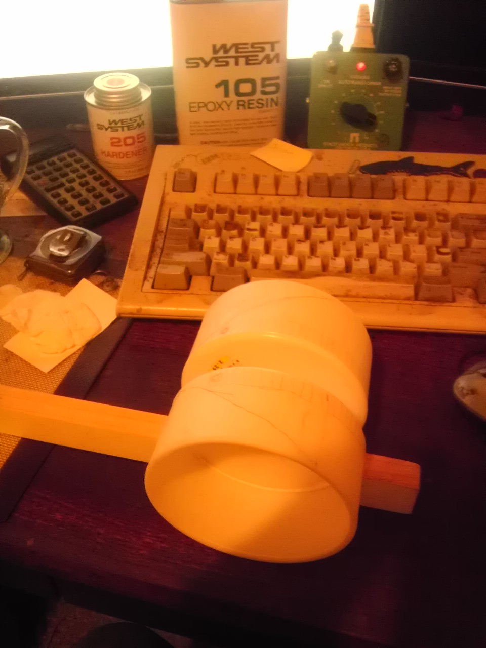
I'm using dia 4.5 inch end caps from PVC pipe, for the gear portion, and I found them in the attic of my garage. I'm going to try to slice off some of the cap to reduce weight, and improve it's looks. I'll take a close up pic so you can see the pencil schematic I've laid out.
I found some half round wood in the garage too, which should work well for the bearingless parts.
The wooden arms were found free curb side over the past couple of years.
Glass windows were found curb side last year, too big to bring into the house, and it will have to be cut to size.
I figure this will be the cheapest way for me to make a 3D printer. I'll document it as I go!
I also bought the epoxy today to glue some of the parts together, as I don't want to see it fall apart, I just want it to work well enough to make me a Simpson.
A2
The cheapest, and easiest 3D printer: hacking junk.
haib, half donkey is best
Edited 5 time(s). Last edit at 08/23/2013 01:59AM by A2.
|
Re: New arm design for Simpson style printer. August 22, 2013 11:59PM |
Registered: 10 years ago Posts: 14 |
Guizmo Wrote:
-------------------------------------------------------
> BloodBlight Wrote:
> --------------------------------------------------
> -----
> > I posted this on the other thread, but I thought
> I
> > would put it here as well:
> >
> > I changed my mind about a dozen times, but here
> is
> > my addition to the project:
> > [www.youtube.com]
> >
> > No belts or cables and no odd shaped gears.
> And
> > this can be simplified even more. You can
> remove
> > the need for the springs by adding a stopped to
> > the end of the rack gears and then putting them
> in
> > a sleeve past the arm.
> >
> > This means the gears would need to be longer
> (this
> > could be an issue as I think about 280MMs will
> be
> > the limit), and a very simple bearing could be
> > used.
>
>
> Hi,
>
> Could you plase post some images? I have no access
> to youtube.
>
> Thanks!
It was my drawing it on a some paper, sorry, I don't have any CAD drawing.
Basically you put in two rack gears mounted to hinging points on one arm with the threads facing each other. Then you place a gear on the other arm that size equals the distance of the two mount points (after taking into account the rack gears width).
As that gear spins, it moves the two points and equal distance in opposing directions.
The rack gears can be kept on the drive gear using ether springs and a bearing or by extending the gears further out and putting a sliding clip on the end.
Sorry, I bet that is clear as mud.
|
Re: New arm design for Simpson style printer. August 23, 2013 12:09AM |
Registered: 10 years ago Posts: 14 |
Shawn.Walker Wrote:
-------------------------------------------------------
> @BloodBlight: so, a completely gear-driven design?
> That could add rigidity/stability, sure. Why do
> you feel it would be "backlash free"? I would
> think switching from belts/lines to gears would
> tend to increase backlash.
Well, I am no engineer, so I could be totally wrong on this. But my understanding is there are two ways you can get backlash. One, from your belts, strings, mounts or whatever stretching. And two, but play in between gears.
In its simplest form there is are only three places that can have play. The arms themselves flexing, the bearing on the upper arm, and the gear on the motor. In theory you backlash limit would be the flex of your arms (unavoidable in any design) plus (ignoring the bearing) the play on a single gear (something that most of the other designs here also have). If these are made of metal and not printed I think you would over torque and force the stepper motor to skip before you saw any backlash.
If you want to use a belt (I don't see how that would reduce backlash), that can be done as well! I recorded a video on that as well, and it is a VERY simple design, but does require two steppers per arm (still using a single motor controller). It would be a direct drive to belt configuration with the belt looping the four points and the motors opposing each other on either arm.


Sorry, only registered users may post in this forum.