New arm design for Simpson style printer.
Posted by Guizmo
|
Re: New arm design for Simpson style printer. October 17, 2013 04:49PM |
Registered: 10 years ago Posts: 979 |
@Guizmo: Just to be clear, I have no problem with changing or evolving goals. I also have no problems with tangential posts. I don't want to come off as a forum Nazi. In fact, I think always trying to stay on point is counter to what it takes to produce new innovative designs. I just thought it would be valuable to have a discussion about what we want to accomplish.
You will have to forgive me. I am a teacher and a large portion of my time is spent teaching the engineering design process. It is my opinion that good design comes from knowing what you want to accomplish and persistence. You would think that knowing what you want to accomplish before you do anything would be obvious but most students have to be taught this. Without direction most of my students will just start doing things without out much thought of what they want to accomplish. They will then get frustrated when they don't have any success because they haven't defined what success is. All that said, I like to restate the goals (which can change) often so we know what success is when we achieve it.
For the record, I have a design in my head that is pretty close to the ideal. It gets rid of all the bearings and all the M8 hardware. I need to play with some completely printable tensioners. In the future, the string for the DLCJ's could be replaced with nylon. I don't print with nylon because of the health concerns and all my hot end mounts are in PLA. I don't know how to get rid of the string for the PGDJ or the spring. I also think we can save on having a bed by keeping the middle hollow which will allow us to print directly on any surface.
I have also thought about ways we could use a high reduction ratio planetary drive to replace the PGDJ. You could drive a the elbow or shoulder directly with that much torque. You could use techniques we are learning form the gear bearings to make it metalless. The main problem is backlash. I think we can solve the backlash problem to some extent by making the carrier springy and bent so that you have to force it to be straight. Gravity is also on our side here. (Meaning, there may be backlash but it should not matter if are always on one extreme of the backlash. However, we would have to set the acceleration to be very small so dynamic forces don't get close to the forces from gravity.)
I want to call this one "BOB Simpson". 1) I like the name Bob. 2) BOltless and Bearingless.
|
Re: New arm design for Simpson style printer. October 17, 2013 05:26PM |
Registered: 10 years ago Posts: 145 |
Well, I don't think of you as a forum nazi. I'm trying to learn as much as I can from this development and from you, so I take all those comments in a positive way. I recognize I need to learn more. Let's keep working on it.
I also have a few ideas, but to be sincere I have little spare time because I have a little girl that loves me and I can resist expending time with her . You have to be with your kids while you can!
Eventually I will post those ideas, I just have to set apart some time to do it.
BTW, I like the Bob Simpson. Now it has a name and a lastname, an indication it's getting closer to be a person
Edited 1 time(s). Last edit at 10/17/2013 05:49PM by Guizmo.
I also have a few ideas, but to be sincere I have little spare time because I have a little girl that loves me and I can resist expending time with her
. You have to be with your kids while you can!Eventually I will post those ideas, I just have to set apart some time to do it.
BTW, I like the Bob Simpson. Now it has a name and a lastname, an indication it's getting closer to be a person
Edited 1 time(s). Last edit at 10/17/2013 05:49PM by Guizmo.
|
Re: New arm design for Simpson style printer. October 17, 2013 06:08PM |
Registered: 10 years ago Posts: 86 |
Greetings from germany
You are right. My kids need me too. The youngest is 13 month old and got some new plastictoys last month. I was surprised that the thing was very stiff. IT was a Garage with two floors. 3 pieces sticked together only with plasticbolts or a tongue with a nose on it like the plasticcap for the battery in a TV remotecontrol. IT is a very long time since i hold the remote...
So i hope you have a simple idea what i was talking about.
Magicworx
P.s.: my oldest (15y) watched a movie where a new world was born and the protagonist (hero) called it planet bob. Do you really want to use bob?
|
Re: New arm design for Simpson style printer. October 17, 2013 06:12PM |
Registered: 10 years ago Posts: 979 |
|
Re: New arm design for Simpson style printer. October 17, 2013 07:07PM |
Registered: 10 years ago Posts: 145 |
|
Re: New arm design for Simpson style printer. October 18, 2013 05:33AM |
Registered: 10 years ago Posts: 86 |
Morning!
I really tried to draw but havent enough time to do it right. Hope you can See what i meant.
42 magicworx
I really tried to draw but havent enough time to do it right. Hope you can See what i meant.

42 magicworx
|
Re: New arm design for Simpson style printer. October 18, 2013 05:59AM |
Registered: 10 years ago Posts: 86 |

|
Re: New arm design for Simpson style printer. October 18, 2013 10:03AM |
Registered: 10 years ago Posts: 145 |
|
Re: New arm design for Simpson style printer. October 18, 2013 03:19PM |
Registered: 10 years ago Posts: 86 |
@guizmo: i took the picture AT work. I was lucky to find a remotecontrol for a radio. The drawing was done at my desk while I was on the phone.
My little boy should be asleep at that time, taking his nap.
My wife called me that my 10yr old daughter was at the hospital and that the poor little girl may have a broken hand. Luck is with the young. The hand wasn't broken.
Now I am home. Hopefully Christmas is coming and I try to convince my wife that "we" need a 3d printer. She love baking. Cakes and many more cookies with and without different toppings. I think she earns a master degree in baking. I am now very interested in liquids printing for her cakes. So she can print pictures on the top layer.
So Wally comes to.mind with different toolheads.
I know I need a filastruder first to produce PET filament. PET is very cheap here and is widely used with food. Its sold as water bottles and after drinking the water the bottle would be thrown away. So we got a recycling effect here. But first things first. Wally isn't officially released and I think there is much potential for improvement with the pla plastic parts.
So good day to you and good night for me
42 magicworx
|
Re: New arm design for Simpson style printer. October 19, 2013 09:33AM |
Registered: 10 years ago Posts: 4 |
nicholas.seward Wrote:
-------------------------------------------------------
> I have also thought about ways we could use a
> high
> reduction ratio planetary drive to replace
> the PGDJ. You could drive a the elbow or shoulder
> directly with that much torque. You could use
> techniques we are learning form the gear bearings
> to make it metalless. The main problem is
> backlash. I think we can solve the backlash
> problem to some extent by making the carrier
> springy and bent so that you have to force it to
> be straight. Gravity is also on our side here.
> (Meaning, there may be backlash but it should not
> matter if are always on one extreme of the
> backlash. However, we would have to set the
> acceleration to be very small so dynamic forces
> don't get close to the forces from gravity.)
>
> I want to call this one "BOB Simpson". 1) I like
> the name Bob. 2) BOltless and Bearingless.[/quote]
I suspect you could do a two-stage planetary gearbox, with a variable ratio on the second one.
I have been thinking of that almost non-stop since that last post.
Motor - Sun 1
Free - Planets 1
Transmit - Case to sun 2
Free - Planets two, non-circular
Effector limb - Case 2, non-circular with varable gear ratio which matches non-circular planetary gears, with the ratio proportional (1/sin(o)) through about 125 degrees.
Alternatively you can leave the planetary set circular and spring them
Alternatively you can use the dual-ring technique you linked to with a variable density of teeth, proportional to the angle. Possibly only 4 moving parts, but the difficulty remains backlash. Number of teeth / degree varying with sin(degree) should work.
|
Re: New arm design for Simpson style printer. October 21, 2013 02:57AM |
Registered: 10 years ago Posts: 86 |
Hi
New not perfect drawings:
Here the tongue with the nose.
I put sticks for rigity on it.
And here the holes.
Now I am working on the string tension problem for portable Wally.
So long
Magicworx
New not perfect drawings:
Here the tongue with the nose.

I put sticks for rigity on it.

And here the holes.

Now I am working on the string tension problem for portable Wally.
So long
Magicworx
|
Re: New arm design for Simpson style printer. October 23, 2013 03:59AM |
Registered: 10 years ago Posts: 1,381 |


Vitamin reduction idea:
To reduce the part count, integrate the main body of the 3d printed geared tuner into the arm.
This also eliminates a vendor, and associated S&H, and it's some thing that can be 3d printed!
You said that mounting the spring and tensioner onto the shoulder arm solves the non-linear problem, is that still an option?
Or am I not understanding some thing ?

It seems trivial to do, and I'm left wondering why it's not being done, obviously I'm not seeing the whole picture if this is not the case.
Geared String Tuner
[www.thingiverse.com]
A2
Edited 1 time(s). Last edit at 10/23/2013 04:00AM by A2.
|
Re: New arm design for Simpson style printer. October 23, 2013 04:52PM |
Registered: 10 years ago Posts: 145 |
|
Re: New arm design for Simpson style printer. October 23, 2013 05:08PM |
Registered: 10 years ago Posts: 86 |
Hi a2
I think that this is a better solution than I was thinking of.
My has only a lever that tensions the string. I wanted to put a spring somewhere but I thought that would be to difficult. I came up with three additional parts. The lever, the screw to fix the string and a plastic bearing. The lever has a hole for the screw that fixes the string. The lever will be pushed back to tension the string. If it is not enough rotate the in quarter steps to tighten the string further. The lever will then be hold by corner.
Here the way of the lever.
Because the lever isn't round it will be hold by this little corner even if its tightened. If its hold enough must be seen. But its definitely possible to integrate it into the arm.
Magicworx
Edited 1 time(s). Last edit at 10/23/2013 05:51PM by magicworx.
I think that this is a better solution than I was thinking of.
My has only a lever that tensions the string. I wanted to put a spring somewhere but I thought that would be to difficult. I came up with three additional parts. The lever, the screw to fix the string and a plastic bearing. The lever has a hole for the screw that fixes the string. The lever will be pushed back to tension the string. If it is not enough rotate the in quarter steps to tighten the string further. The lever will then be hold by corner.
Here the way of the lever.

Because the lever isn't round it will be hold by this little corner even if its tightened. If its hold enough must be seen. But its definitely possible to integrate it into the arm.
Magicworx
Edited 1 time(s). Last edit at 10/23/2013 05:51PM by magicworx.
|
Re: New arm design for Simpson style printer. October 23, 2013 11:51PM |
Registered: 10 years ago Posts: 1,381 |
@Guizmo
nicholas.seward said:
"I designed it so that the spring puts 3.5+lbf of tension into the string at that point."
~3.5 lb tension, I think a 3d printed guitar string tuner should work, less creep over time.
Material choice is always important, and if a component fails it can be replaced with a more robust one.
A2
|
Re: New arm design for Simpson style printer. October 24, 2013 12:58PM |
Registered: 10 years ago Posts: 1,381 |

Another guitar string tuner on Thingiverse
Makerlele_MK1_plus
[www.thingiverse.com]
Edited 1 time(s). Last edit at 10/24/2013 12:59PM by A2.
|
Re: New arm design for Simpson style printer. October 25, 2013 01:59PM |
Registered: 10 years ago Posts: 145 |
|
Re: New arm design for Simpson style printer. October 31, 2013 08:19PM |
Registered: 10 years ago Posts: 20 |
@nicholas.seward Hey I love the design of the simpson! I just became aware it through your interview with 3dprinting industry.
I would love to get involved if you need another engineer brain. I haven't had a chance to read every post in the thread to follow the current development of the gear design. I noticed that there was a big discussion about compensating for the bolt diameters as the arm moves though its motion because the string path changes length. A possible geometric solution for the problem would be to make the radius of the herrigbone gears change slightly to compensate for the change in the string path length. This would make the herringbone center to center distance change enough to compensate for the length change. It would also mean possible part reduction in that you no long need the compliance of the spring. Generating the curve for a variable radius herringbone is more complicated but definitely doable.
Are there any other current design challenges that are needing to be addressed? A to do list would be great.
Again I would love to help in any capacity that is needed.
Let me know,
Michael
|
Re: New arm design for Simpson style printer. October 31, 2013 10:25PM |
Registered: 10 years ago Posts: 979 |
@dexterm2003/everyone: I can't really speak for everyone but I can line out what I think are areas of need.
The basic "Simpson" geometry is proven at this point. We are just playing with variation on a theme now. What I am saying is crazy (dumb) ideas like this can never be part of the Simpson family due the different geometry of the machine. Not that we can't branch off and make new machines but for a Simpson machine we are stuck with the Simpson geometry.
What can be changed? Joints and drives are the main focus right now. We are already cooking up BOB Simpson that is going to be BOltless and Bearingless. Currently, I have a pretty clear idea of how to design everything for BOB but it will be more of a novelty then an everyday printer. To move BOB from a novelty to a serious contender we need a maintenance free DLCJ (Double Lamina Compliant Joint) or something equivalent. (I actually just got an idea. How robust is nylon? How many cycles to failure could we get out of bending a 15mmx1mm printed strip back and forth? I guess this is a function of the size of the drums used for the DLCJ. If so, then we size it to spec.)
I am undertaking BOB as more of a learning experience. It won't be a replacement for GUS it will be a platform for trying out different vitamin reducing techniques. Hopefully some of the new techniques will prove useful and will make their way into mainstream designs.
For me, the biggest weak spot and area of need is the drive. The PGDJ (Proportional Gear Drive Joint) is admittedly awesome but there are some major weaknesses. Let's consider the string routing to be a non-issue. (I think I have a method that can keep the spring and the tuner on the slave arm and will reduce the max error to around 25 microns. I think that is safely below other sources of errors. Besides, we can put the spring and the tuner on the motor arm and it is perfect.) The biggest problem is the time and concentration it takes to string an arm. That is followed by a big question mark about how long the string will last. I will put GUS through some tests as soon as I find some time to put him back together. (He was shipped back from NY assembled and escaped with just one major injury. I just haven't had any time.)
I ramble on but we either need to replace the PGDJ with something simpler or we need to refine the PGDJ. I know many will want to put actual pulleys on the joint instead of having the fishingline slide over the bolts. I think that is the wrong direction. I don't know what the final solution will be but I know I don't like the current PGDJ for a production bot.
I am sure there are other things that need to be done but that will give you something to think about. Maybe others on this forum will chime in with what they think we need to work on.
The to do list is pretty simple.
*Play around with DLCJs until we have a fairly maintenance free solution.
*Find a different drive or improve the PGDJ.
*Test how long the string will last in its current configuration.
*Improve filament drive. (I am thinking about switching from a direct pinch wheel to a much larger geared pinch wheel. I also think I need to move to 3mm filament.)
*Replace the herringbone arms with double herringbone arms. (This is just a matter of time.)
*Improve calibration routine and/or add auto-calibration. (I think we can put together an easy manual calibration routine but again I just need time.)
For the most part, the engineering challenges aren't that crazy hard. The biggest problem is time. I am pretty much committed to making BOB but he is in line behind 4 other printers (no joke, Sextupteron, Tilt-n-Twirl, StringSpring, a 1-arm SCARA, Mega Simpson, etc.) and those are just full printer projects. There are a lot of non printer projects to go between the big builds. That is not to mention the software that I want to work on. That is not to mention the challenges of starting a business. That is not to mention my current day job. (After writing all that out it would seem reasonable to put BOB off for a year or two. I sincerely hope that someone will beat me to it. Also on the time front, I will revise GUS a bit and will refine his software but after those design changes he will be mostly in the hands of the community.)
Bottomline: open source design is awesome. I particularly love the brainstorming process when you have a large range of diverse experts. However at the end of the day, someone has to take ownership and be the driving force in order to bring it home. So the real to do list is just one item. *Make a Simpson the way you think he should be made.
(I have the idealist goal that there will eventually be a place on the web where many people can collaborate on a mechanical design. After the design is "complete", anyone can order the design and all the parts will just show up at their door. Kind of like SourceForge for hardware. I think I will call it ConceptFORGE.)
Edited 1 time(s). Last edit at 10/31/2013 10:27PM by nicholas.seward.
|
Re: New arm design for Simpson style printer. October 31, 2013 11:56PM |
Registered: 10 years ago Posts: 167 |
nicholas.seward Wrote:
-------------------------------------------------------
> How robust is nylon? How many cycles to
> failure could we get out of bending a 15mmx1mm
> printed strip back and forth?
If nylon doesn't work, how about aluminum? I'm sure most people would have easy access to a few soda/beer cans they could cut up.
|
Re: New arm design for Simpson style printer. November 01, 2013 12:07AM |
Registered: 10 years ago Posts: 979 |
@AbuMaia: I like it. 1) How do you attach the ends of the strips? 2) How do you tension the system?
With nylon I was thinking that the bands and the drums could all be one print. I could then snap or screw on herringbone caps with a conical seat so they would tension the bands and register the joing. I assume I could do the same with aluminum if I had mounting slots with multiple right angles. However, it seems like it would be very tricky to get all the bands to be the same.
With nylon I was thinking that the bands and the drums could all be one print. I could then snap or screw on herringbone caps with a conical seat so they would tension the bands and register the joing. I assume I could do the same with aluminum if I had mounting slots with multiple right angles. However, it seems like it would be very tricky to get all the bands to be the same.
|
Re: New arm design for Simpson style printer. November 01, 2013 02:46AM |
Registered: 10 years ago Posts: 20 |
I would be very surprised if printed nylon lasted over a long period of time before failing. plastic is not good as a flexible member the diameters would have to be way to big.aluminum is also bad as a flexible member because it will fail under repeated fatigue stresses. the best bet for a flexible band would be a stainless steel band. they make high accuracy drives called capstand drives using steel bands.
as far as stringing issues would it be possible to open one of the faces to expose the string path which could possibly make it easy and then close the face with a plate or second half of some sort. the other question I would have is there some way of having it string it self through with a self feeding mechanism of some sort and guides and races that the cable will be pushed and pulled through. another option would be to switch from a string to another drive mechanism such as a toothed design of some kind such as synchro chain, of there are cables that that tooth like features along their length. I guess another thought would be if the stringing difficult is due to it being buried along the center line would it be possible to have two lines run one on each side so that they are exposed and easy to get to. balancing the tension on the two lines could be an issue but could be addressed.
you mentioned that pulleys along the cable path is not the right solution. why do you feel that it. yes it would add more parts but it is the reliable solution that reduces the wear and maintenance aspect.
is there a goal that all of the drive components will be printable? there are tread offs with that approach. as you well know I'm sure.
|
Re: New arm design for Simpson style printer. November 01, 2013 03:54AM |
Registered: 10 years ago Posts: 979 |
@dexterm2003: I guess I didn't make this very clear. For me there are two goals.
1) BOB Simpson: If a vitamin can be removed then you are honor bound to remove it. He is a test bed for different vitamin reduction techniques. The idea is that at least a few of the techniques will feedback into mainstream designs. I would design him only to be a novelty/curiosity. I really think I can do the whole bot without bearings or any metal fasteners.
2) GUS Simpson: He is the current production branch. If he has a vitamin then it better be an M8, M3, or a 608. The only two exceptions will be for a some tiny springs and $1 guitar tuners. (I currently have no plans to replace 608 joints with DLCJs.)
I really like the idea of having the cable run on both sides of the arms and I am revisiting my no pulley policy. I have an idea blooming as we speak. The idea will require 14or15 608's per arm pair. That kinda sucks but for $0.25/bearing these pulleys will only add $10 to the overall design. I will see if I can sketch something up. The one interesting point is I need a spool that sticks out of both sides. How do you drive this spool? My current plan is with some printed bevel gears so I can keep the motor in about the same spot it is now. I can already hear people starting to say that "b" word. (backlash) However, the spring that I put at the termination of one side of the string will always remove any play. I am planing for the string to go up one side and down the other and then terminate. The additional mechanical advantage that I need can be had through the bevel gears.
Now that I said all that, the reason I wanted to stay away from pulleys is the shear number of bearings that would be required as you can see from above. Even at 25 cents a pop the bearings will make up almost half of the costs for the mechanicals. Additionally, if the string is left in the center and we add pulleys it will be super annoying if a string ever pops off a pulley.
I will play with the new idea and post it here to see if it has any legs.
Also, at the cost level that we are playing at, $40 mechanicals, we can't afford much. We have $20 for plastic which is about 1kg. That leaves $20 to buy all the bolts and bearings. One Synchro chain will kill our budget.
I am trying to hit the <$200 mark for a simple Simpson. $40 mechanicals + $40 steppers + $20 hot end + $100 electronics=$200 We know it is possible.
|
Re: New arm design for Simpson style printer. November 01, 2013 11:44AM |
Registered: 10 years ago Posts: 20 |
with those design criteria it would seem like if you split the arms in half so that during assembly you can easily string the arm joint and then snap the second half of the arm on to finish then tighten everything up it would cut your pulley induced bearing count in half. it adds more printed parts but it would remove $5 from the mechanical cost. are you extruding your own filament yet? if you do you could reduce the plastic cost to $1-2/kg. one Lyman filament extruder is about $100 and can make enough filament to keep several printers busy. is there an electronics thread yet? it seems to me that a custom board could reduce the cost to around $50.
could you send me cad of the current design so that I can understand how all of components are working together. I am a little confused as to why a bevel gear would be needed for the drive.
on the extruder idea I just finished the build of one and I am putting the finishing touches on it and let you know how it goes.
Edited 1 time(s). Last edit at 11/01/2013 11:45AM by dexterm2003.
|
Re: New arm design for Simpson style printer. November 01, 2013 12:42PM |
Registered: 10 years ago Posts: 20 |
@nicholas.seward you mentioned that you were thinking of replacing the PGDJ with a high reduction planetary drive. I am not a fan of planetary gear sets especially if you want to do fast dynamic moves because the shear stresses on the gear teeth are really high and they will not stand up to those types of stresses also backlash is a major problem with planetary gear sets. You should consider using a cycloid gear reducer if you want a nice gear reducer. Like this one.
[www.thingiverse.com]
This reducer is almost completely printed except for the bearings and a few screws. it is also a 100:1 gear reducer. This is a two stage version but achievable ratios are in the rang from 3:1 to 1000:1 easily with just one or two stages. The other major advantage is that the cycloid gear teeth are way stronger than standard gear teeth and 1/3 of the teeth are in contact at all time rather then two standard gear teeth. The other major advantage is backlash reduction. Cycloid reducers have very low backlash and there are ways that you can make it true zero backlash.
That is my two cents if you go away from the PGDJ to a geared drive join combo.
|
Re: New arm design for Simpson style printer. November 01, 2013 11:35PM |
Registered: 10 years ago Posts: 167 |
@nicholas.seward Regarding changes to the PGDJ, I had this idea. It's probably been mentioned before and discarded. Instead of the hassle of routing the string around two sets of bolts, why not have a spring between two bolts and the string going directly to a third? The spring, if strong enough, could be used to extend the arm when the stepper eases tension, while the string/ribbon/belt attached to the stepper and third bolt would contract the arm. Please forgive the quick-and-dirty paint edit image.

|
Re: New arm design for Simpson style printer. November 02, 2013 09:10PM |
Registered: 10 years ago Posts: 20 |
I am not a fan of that Idea. Having only a spring to hold one side of a joint is asking it to come apart. The other thing is that the mechanical advantage of the motor changes drastically with the angle of the arm and it might be easy to over shoot. It is simple but not high performance. The stepper motor will have to fight the spring through it's motion. I think that a printable gearbox joint arm would perform much better. I will see if I can CAD up an arms with a cycloid gear box soon. What gear ratio are you thinking of for the arm joint?
|
Re: New arm design for Simpson style printer. November 06, 2013 07:20PM |
Registered: 10 years ago Posts: 145 |
Ok guys,
It is time for an update from my part. The goal of this redesign is to improve the Simpson user experience by avoiding the need of a complicated stringing.
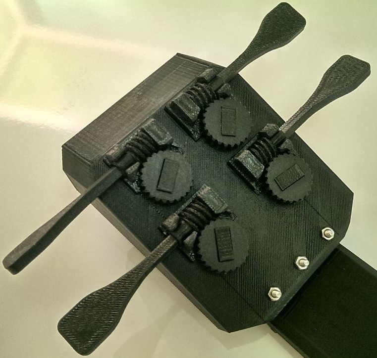
The idea focuses on using bowden cables (think bike brakes) as the "movement transmitters", which are very easy to route, to tension, cheap and strong. Aditionally, their use also give us the advantage of positioning the motor somewhere else, reducing the inertia and thus increasing the speed capacity of the arm.
This design has to be polished more, specially regarding the reduction to drive the main barel, as the current worm gear, although it looks good and compact, will inevitably have some backlash. We could also use a string, with a much more easy routing than the current design or even a zero backlash belt.
I´ll call this design the Remote Drive GUS (RDGUS).
I see this design could be easily morph into a 3 DOF robotic arm with the apropiate modifications. That´s something I´d like to do.
Please tell me your opinion.
Thanks
It is time for an update from my part. The goal of this redesign is to improve the Simpson user experience by avoiding the need of a complicated stringing.
The idea focuses on using bowden cables (think bike brakes) as the "movement transmitters", which are very easy to route, to tension, cheap and strong. Aditionally, their use also give us the advantage of positioning the motor somewhere else, reducing the inertia and thus increasing the speed capacity of the arm.
This design has to be polished more, specially regarding the reduction to drive the main barel, as the current worm gear, although it looks good and compact, will inevitably have some backlash. We could also use a string, with a much more easy routing than the current design or even a zero backlash belt.
I´ll call this design the Remote Drive GUS (RDGUS).
I see this design could be easily morph into a 3 DOF robotic arm with the apropiate modifications. That´s something I´d like to do.
Please tell me your opinion.


Thanks
|
Re: New arm design for Simpson style printer. November 06, 2013 11:04PM |
Registered: 10 years ago Posts: 1,381 |
@ Guizmo
Remote Drive GUS (RDGUS)
Very cool! > <
<
I also like where you located the end-stop on the worm wheel.
I imagine to rotate the pillar you will need to mount the remote drive, and the pillar onto a common lazy Susan?
If the bike cable is long enough, I can envision the pillar rotating without having the worm drive mounted to it.
To make it a SCARA robot, the end effector needs a pivotal arm as well.
A2
Remote Drive GUS (RDGUS)
Very cool! >
<I also like where you located the end-stop on the worm wheel.
I imagine to rotate the pillar you will need to mount the remote drive, and the pillar onto a common lazy Susan?
If the bike cable is long enough, I can envision the pillar rotating without having the worm drive mounted to it.
To make it a SCARA robot, the end effector needs a pivotal arm as well.
A2
|
Re: New arm design for Simpson style printer. November 07, 2013 10:54AM |
Registered: 10 years ago Posts: 145 |
Thanks A2,
I put no endstop, so perhaps you´re talking about the mounting holes for the cable.
Well, the idea is that the drive is mounted under the base or where most apropiate. I wouldn't like the idea of moving it along the arm because that's in fact one of the goals, to remove its mass from the arm.
And regarding the robot arm, I'm nor planning to make it a scara, as I don't like them too much and this design doesn't seem to fit on the scara architecture. I'd rather making a standard arm (if that's the correct way to call them). Of course I'd need 2 more degrees of freedom at the base, just like the current Simpson, but controlled, and a way to maintain the end efector parallel to the base (just like industrial palletizing robots).
My biggest concern with this design is the reduction of the drive. I like the worm but I don't trust it.
What do you guys propose?


Sorry, only registered users may post in this forum.