A new line of investigation, Radial+Z
Posted by Sabsy
|
A new line of investigation, Radial+Z October 16, 2013 06:45AM |
Registered: 10 years ago Posts: 2 |
Hi everyone, this is my first foray into the community and so I must apologize for any ignorance on my part. I am entering a new period of my life and have decided I would like to look at operating a FDM machine. Unfortunately I'm not bonkers crazy or bankers draft rich so buying one outright isn't an option for me, not an option considering all the points of failure I see in contemporary designs anyway.
Be it Cartesian, Delta, SCARA or Polar, I haven't found a design that doesn't come with baggage. The reality of the matter is that most of us who construct these machines do it without the resources and capabilities of precision that could be afforded in an industrial environment. With each consecutive linkage between stepper and end effector, the tolerances add up and can result in deviations and errors. Given we start off with difficulty ensuring parallelism already, designs that increase our difficulties further just don't sit well with me.
But this got be thinking, and I eventually came across something on youtube that sparked an idea.
This gentleman did something I've not seen anywhere else, he found a way of using a single true surface as datum for all 3 axes. What gets me about Cartesian designs is that not only does each axis have to be perfectly perpendicular to the others, the nesting of axes cause chain amassing of error, and usually on X and Y there is a second parallel rail there for stability. With Deltas all 3 columns must be perfectly parallel, each double linkage between rail and effector has to be perfect and any deviations will cause deviation on all axes.
My discussion here is limited to the horizontal plane as the vertical one is an entirely different issue with its own set of problems (delamination etc)
However the design in the video, though it appears to solve a number of problems, creates many more.
Though all axes maintain parallelism, or radial predictability, the build envelope to footprint ratio is terrible. His choice to move the platform and workpiece ensures that this design could not be operated at speed due to inertia and fragility.
Lowering the work platform from the true surface (hence why I am concentrating solely on the horizontal plane at present) and instead using the radial arms to manipulate the hotend would be much better.
The linear nature of the arms extension creates an even (albeit radial) distribution of addressable coordinates and the footprint has been reduced greatly, however space is wasted allowing the drive rods to retract.
Changing the drive rods to pivoted linear rails provides the same favorable coordinate layout and saves a little more footprint while still keeping the end effector only one linkage away from grounding. This arrangement sets a precedent, a pivoted linear rail can slide flat and true on both sides of a hole in our single, true surface.
Expanding on the theme, what happens when the pivot points are moved closer to work platform? The topmost portion of the build envelope is good and usable however as we approach the bottom of the envelope we run into the issue of the radial axes being less perpendicular and more parallel, resulting in a deadzone pictured, where the majority of the force from the linear rail goes into working against the other linear rail rather than moving the hotend.
The addition of a 3rd radial axis (though absurd since we are talking about 3 axes on a single plane) solves the deadzone problem by ensuring the no direction of travel at any point in the build envelope is more than 60 degrees from a radial axis to propel it. However the mechanism begins to get bulky, each axis would have to cross the work area at a different, non-overlapping height and then drop back down by as much on the other side to reach true. This opens up the possibility of torsion forces twisting the higher rails up off of the true surface.
But 3 axes to do the work of just X and Y (albeit without having to involve challenging fabrication of perfectly parallel rails)? Surely there must be a better way, perhaps going back to 2, and having a single radial arm with the second articulating it at the end rather than the end effector. This creates an unbalanced coordinate system however, in the area marked any movement on the blue axis would require much more time and travel than it should, resulting in a slowing in that area at best and a print failure from alternating speed at worse. At least though, with only one linear rail crossing the work area its easier to keep things true with no overlap.
Having the steppers and linear rails on the outside of the envelope does seem a good idea, lightening what little resistance they added to articulation in previous iterations. Returning once again to the 3 axis concept, at least the radial arms crossing through the work area are now simple rails articulated from the outside, they can be kept thin and close to the true surface, minimizing the danger of torsion. Apart from weight of the hothead spread among them all the forces they experience are horizontal.
That forms the basis of my thinking so far, a true surface being used to keep everything on the horizontal plane parallel through the use of pivots. Unfortunately the solutions I have come up with are all much much more complicated than the less space efficient earlier iterations.
If only there were a way to create the effect of a distant pivot point without the need to actually have it so far away.
Anyhow, I would love to hear your comments and critiques. My aims with this design are simply fast printing speed and ease of attaining effective precision.
Be it Cartesian, Delta, SCARA or Polar, I haven't found a design that doesn't come with baggage. The reality of the matter is that most of us who construct these machines do it without the resources and capabilities of precision that could be afforded in an industrial environment. With each consecutive linkage between stepper and end effector, the tolerances add up and can result in deviations and errors. Given we start off with difficulty ensuring parallelism already, designs that increase our difficulties further just don't sit well with me.
But this got be thinking, and I eventually came across something on youtube that sparked an idea.
This gentleman did something I've not seen anywhere else, he found a way of using a single true surface as datum for all 3 axes. What gets me about Cartesian designs is that not only does each axis have to be perfectly perpendicular to the others, the nesting of axes cause chain amassing of error, and usually on X and Y there is a second parallel rail there for stability. With Deltas all 3 columns must be perfectly parallel, each double linkage between rail and effector has to be perfect and any deviations will cause deviation on all axes.
My discussion here is limited to the horizontal plane as the vertical one is an entirely different issue with its own set of problems (delamination etc)
However the design in the video, though it appears to solve a number of problems, creates many more.

Though all axes maintain parallelism, or radial predictability, the build envelope to footprint ratio is terrible. His choice to move the platform and workpiece ensures that this design could not be operated at speed due to inertia and fragility.
Lowering the work platform from the true surface (hence why I am concentrating solely on the horizontal plane at present) and instead using the radial arms to manipulate the hotend would be much better.

The linear nature of the arms extension creates an even (albeit radial) distribution of addressable coordinates and the footprint has been reduced greatly, however space is wasted allowing the drive rods to retract.

Changing the drive rods to pivoted linear rails provides the same favorable coordinate layout and saves a little more footprint while still keeping the end effector only one linkage away from grounding. This arrangement sets a precedent, a pivoted linear rail can slide flat and true on both sides of a hole in our single, true surface.

Expanding on the theme, what happens when the pivot points are moved closer to work platform? The topmost portion of the build envelope is good and usable however as we approach the bottom of the envelope we run into the issue of the radial axes being less perpendicular and more parallel, resulting in a deadzone pictured, where the majority of the force from the linear rail goes into working against the other linear rail rather than moving the hotend.

The addition of a 3rd radial axis (though absurd since we are talking about 3 axes on a single plane) solves the deadzone problem by ensuring the no direction of travel at any point in the build envelope is more than 60 degrees from a radial axis to propel it. However the mechanism begins to get bulky, each axis would have to cross the work area at a different, non-overlapping height and then drop back down by as much on the other side to reach true. This opens up the possibility of torsion forces twisting the higher rails up off of the true surface.

But 3 axes to do the work of just X and Y (albeit without having to involve challenging fabrication of perfectly parallel rails)? Surely there must be a better way, perhaps going back to 2, and having a single radial arm with the second articulating it at the end rather than the end effector. This creates an unbalanced coordinate system however, in the area marked any movement on the blue axis would require much more time and travel than it should, resulting in a slowing in that area at best and a print failure from alternating speed at worse. At least though, with only one linear rail crossing the work area its easier to keep things true with no overlap.

Having the steppers and linear rails on the outside of the envelope does seem a good idea, lightening what little resistance they added to articulation in previous iterations. Returning once again to the 3 axis concept, at least the radial arms crossing through the work area are now simple rails articulated from the outside, they can be kept thin and close to the true surface, minimizing the danger of torsion. Apart from weight of the hothead spread among them all the forces they experience are horizontal.
That forms the basis of my thinking so far, a true surface being used to keep everything on the horizontal plane parallel through the use of pivots. Unfortunately the solutions I have come up with are all much much more complicated than the less space efficient earlier iterations.
If only there were a way to create the effect of a distant pivot point without the need to actually have it so far away.
Anyhow, I would love to hear your comments and critiques. My aims with this design are simply fast printing speed and ease of attaining effective precision.
|
Re: A new line of investigation, Radial+Z October 17, 2013 12:51AM |
Registered: 11 years ago Posts: 979 |
From what I can glean, you want a simple 2D parallel robot.
I would encourage you to look at the moving platform again. A platform can be very light and the plastic that gets printed on it is also very light. Unless you plan on going with a Bowden setup then you will be stuck with the mass of a NEMA17/NEMA14 motor on the effector. It would be an easy to make a platform lighter than that. As I see it, it is easy to keep a platform flat than it is to keep an effector perpendicular to a surface. (I am not saying go with a moving platform. I like static beds with my own designs but if you are discarding it because of weight and weight alone then you should have a look again. BTW, check out Wally, Simpson, Tripteron, Morgan, Sextupteron, etc if you want to dig into parallel robots. Check out Polar3D just for fun.)
Okay, back to simple 2D motion ideas.
*Consider an equilateral triangle. Have a constant force spring extend from one vertex and string driven by steppers from the other two. Have a two link arm that is only actuated by the strings. The arm is just to keep the hot end perpendicular and constrained to only move a one z level. Skydelta is doing this in 3 dimensions.
*Consider a modification of Wally's XY or Morgan's XY. I have been thinking about how you could possibly power an elbow on one side of Wally's 5 bar linkage and a shoulder on the other side. I haven't done the math but I think it might get you better coverage vs footprint. Morgan's setup gets you a very big footprint at the cost of a hole in the middle.
*etc.
I would personally try to eliminate linear rods/slides. For you, I think this would make a lot of sense. You say that you don't like the cumulative slop from serial robots. Linear motion is expensive if you get rid of most of the slop. Radial motion on the other hand will cost you two 608 bearings at 25 cents a pieces and once you side load them any play they had is now gone. In summary, cheaper and less slop.
I think my next robot design is actually going to be a serial robot. (The sum of the slop should be small with a well designed machine.) I want to make a 1 arm SCARA.
|
Re: A new line of investigation, Radial+Z October 17, 2013 02:44AM |
Registered: 10 years ago Posts: 2 |
My intent indeed was to use a Bowden tube to keep weight off of the end effector and ensure the fastest possible speeds. As for a platform I do worry that the weight of glass and a hotplate would slow maneuvering speed and as height of the workpiece increases so does the risk of it wobbling and tipping under high speed. So that was my thinking there.
I was very much hoping you would reply Nicholas, I have been watching your development of Simpson for some time so I knew that if you chimed in you would do so with genius. I had considered using 2 link arms to maintain Z-position however I dismissed the idea due to the fact that any sideways torsion slop in the joints would translate to an ever increasing Z displacement depending on the length of extension at the time. This has been one of the main things I have been thinking about, slop perpendicular to the pivot is a much greater enemy than slop in the concentricity of the pivot. Consider a rod with a 9mm hole over an 8mm pivot, force applied along the rod can only shift its pivot end positionally 1mm out of center in any direction, but in that same arrangement it is able to twist a disconcerting number of degrees out of right angle, allowing the other end of the rod to move gigantic distances (compared to the 'mere' 1mm in the previous example). This is why I am adverse to bar linkages that are not grounded to a true surface somehow, because their angular slop is translated into positional slop that magnifies as length increases.
However, I said I was expecting genius from you and I definitely was not disappointed, string and tension! Two things that were figuratively under my nose the entire time being discussed in other threads. A string under tension is straight and can literally reel its length.
You have most certainly given me things to think about, and gotten rid of my pesky and bulky linear rails.
I will definitely be coming back with new designs.
|
Re: A new line of investigation, Radial+Z October 17, 2013 10:13AM |
Registered: 11 years ago Posts: 979 |
I think you could engineer a very light and stable table that moves. If I was to go this route, I would have a thin plate of aluminum. (I would have to do the math to see how thin I could go but still be able to maintain flatness with the stress of a large print.) A kapton sticker on the top and a flexible heat pad on the bottom won't add much weight. However, I am not here to steer you away from a static bed. Static beds are awesome.
The revolute joints that I use are a second order or third order contributor to the play in my machines. The flexibility of my links is the number 1 contributor to any slop/play. There are two ways to fix that. 1) Don't cantilever. Have 3 two link idler arms meet in the middle if you want. 2) Increase the cross section of the idler arms. The rigidity goes up with the height of the arm to the 3rd power. Of course that is just for simple bending and we also have torsional stiffness to worry about. However, an idler arm by definition will have very little stress on it.
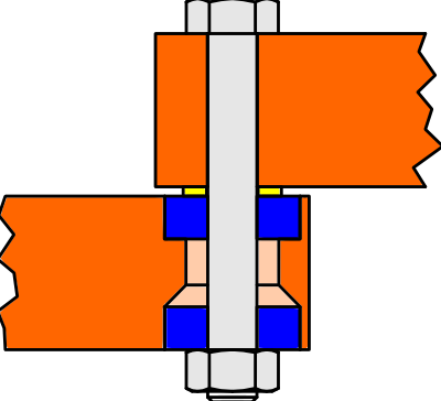
Here is a simple revolute joint that I use everywhere. The bearings are essentially melted in so no play there. The holes are just barely drilled out. The bolts and the bearing inner diameter only different by less than .1mm. Modern bolt heads also have a fillet under the head which centers the bolt in the bearing. The bolt tension holds everything flat so the forces have to be outside the realm of 3D printing to get any shifting. However, you could replace the washer with an integrated conical one and you would have a near perfect joint. If you get a chance to play with a joint like this I am sure you would safely assume that nothing but higher order error can come from it. (BTW, Simpson and Wally wouldn't work if these joints had even the slightest amount of play.)
I will see if I can get the link to the original thread that produced Wally. We talked about a bunch of crazy ideas.
I can't wait to see what you come up with.
Edited 3 time(s). Last edit at 10/17/2013 05:55PM by nicholas.seward.
|
Re: A new line of investigation, Radial+Z October 18, 2013 08:52AM |
Registered: 15 years ago Posts: 401 |
I just have to be pedantic for a moment. A string in tension is not straight. It follows a catenary curve.
I understand what you're trying to achieve, but I think you may have missed something with the linear actuators. The problem with linear actuators is that they require linear bearings. Linear bearings and linear rails have a lot of problems.
1) Linear rails aren't linear under load.
2) Linear rails are expensive
3) Linear bearings must be matched by their linear rails. A linear bearing with hard-steel ball bearings will cut grooves into many linear rails.
4) Linear bearings are expensive if you want to eliminate slop.
5) Driving linear actuators is hard. Very few electrical machines move in straight lines. Most of them spin. Converting from spin to linear motion can be done with either belt drive, string drive, or worm gears (threaded rod is a really long worm gear). Each of these has disadvantages. Belt drive introduces slop. String drive requires tensioning. Worm gears frequently have eccentricity and backlash. Zero backlash nuts add friction.
6) Linear rails aren't scalable. The larger you get, the larger the rails you need. Larger rails are MUCH more expensive. If you need to maintain rigidity, you start needing linear rails that have mounting flanges. Those require pillow blocks with slots, which are more expensive.
By contrast, polar bearings are amazing.
1) polar bearings are self-contained.
2) polar bearings don't lose accuracy under off-axis load (Nick may correct me on this)
3) high quality polar bearings are cheap.
4) driving polar actuators is easy. Mostly, this is because polar actuators use the same plane of motion as rotating motors.
5) Polar actuators are scalable. You can make your arms longer and you have the option of either adding more of the same bearing or using larger bearings. Larger bearings don't get a lot more expensive.
Sorry, only registered users may post in this forum.