Delta robots
Posted by philwaud
|
Re: Delta robots January 08, 2010 09:12AM |
Admin Registered: 16 years ago Posts: 13,884 |
Hi Sebastien,
... all my actual projects not concerning gas-sensors or thermal conductivity measurement are my own IP and for free
Most of my work in micro-/nanotech and microassemnbly in the last 15 years was under NDA for 1 to 3 years, so it now should be free too
Only the pico-dispenser (dispensing droplets of high viscous fluids with sizes in microns or submicrons) isn't free, but it's patented and so partially disclousured too
But it would be a really big job pouring all the infos in text (especially english ) ...
) ...
Viktor
... all my actual projects not concerning gas-sensors or thermal conductivity measurement are my own IP and for free
Most of my work in micro-/nanotech and microassemnbly in the last 15 years was under NDA for 1 to 3 years, so it now should be free too
Only the pico-dispenser (dispensing droplets of high viscous fluids with sizes in microns or submicrons) isn't free, but it's patented and so partially disclousured too
But it would be a really big job pouring all the infos in text (especially english
) ...Viktor
|
Re: Delta robots January 08, 2010 06:47PM |
Registered: 15 years ago Posts: 104 |
Mmm, yes I'm extremely gpl friendly.
If there is enough interest in collaboration in the early stages then I would be willing to write up everything I have. Otherwise I'll wait until I have a working prototype and know its going to work before bothering. I'm still in the, design phase. That being said, if there is interest in the models I'm doing, then I'll release them early as GPL, with the hopes of getting help refining them.
If there is enough interest in collaboration in the early stages then I would be willing to write up everything I have. Otherwise I'll wait until I have a working prototype and know its going to work before bothering. I'm still in the, design phase. That being said, if there is interest in the models I'm doing, then I'll release them early as GPL, with the hopes of getting help refining them.
|
Re: Delta robots January 10, 2010 05:49AM |
Admin Registered: 17 years ago Posts: 1,791 |
Lawrence
Here's a good place to keep notes, drawings, files, video, links and so on. Because the kinematics is universal, and some people are good at making stuff, and some people are electronics geeks and so on.
You're welcome to use it as much as is fun and useful.
[objects.reprap.org]
That's along with this thread and your project blog.
|
Re: Delta robots January 10, 2010 05:52PM |
Registered: 14 years ago Posts: 21 |
Lawrence,
i have finished the mecahnical part of a delta with NEMA 17 Steppers lately and am now trying to get the software running so i can test it.
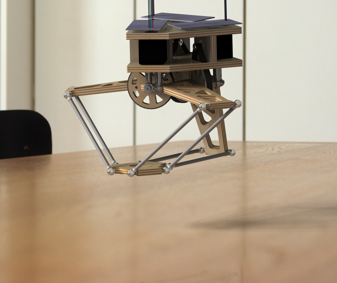
For the moment i just can attach a drawing, i have not photographed the Delta yet. It is using magnetic balls as joints together with flathead imbus screws. (Based on Vistors tripod work). The design can be simplified so that you can get rid of all drilling operations after lasercutting by dividing the 10mm thicknesses into 2*3 and 4 mm layers. I have not yet worked this out completely.
I have also a render, but this is too big to attach.
Cheers,
Torsten
i have finished the mecahnical part of a delta with NEMA 17 Steppers lately and am now trying to get the software running so i can test it.
For the moment i just can attach a drawing, i have not photographed the Delta yet. It is using magnetic balls as joints together with flathead imbus screws. (Based on Vistors tripod work). The design can be simplified so that you can get rid of all drilling operations after lasercutting by dividing the 10mm thicknesses into 2*3 and 4 mm layers. I have not yet worked this out completely.
I have also a render, but this is too big to attach.
Cheers,
Torsten
|
Re: Delta robots January 10, 2010 09:49PM |
Admin Registered: 17 years ago Posts: 1,791 |
I have also a render, but this is too big to attach.
Torsten, That's utterly cool. If it's convenient, you can wiki it at
[objects.reprap.org]
Or leave it up to the library gnomes.
Torsten, That's utterly cool. If it's convenient, you can wiki it at
[objects.reprap.org]
Or leave it up to the library gnomes.
|
Re: Delta robots January 10, 2010 10:40PM |
Registered: 14 years ago Posts: 458 |
|
Re: Delta robots January 11, 2010 03:00PM |
Registered: 14 years ago Posts: 21 |
I'll try to fill some of the spaces in the wiki for this topic. But please be patient, it might take a while.
Optimum tibia/thigh ratio etc. and a lot of helpfull information on deducing forward and inverse kinematics can be found in the PHD Thesis of R.E.Stamper and in general at [www.parallemic.org].
The hard bit now is doing all that c(#) firmware stuff. The bits and pieces are there, just putting it together is proving to be a challenge.
For the render, please do not mind that the whole thing is hovering midair... i was just too lazy to design a frame
Same reason why the prototype sits on the table upside down...
Maybe this could also be a used as inspiration to make a design which is better for repraping the whole thing.
So far for now, i hope i have the firmware up and running soon.
Cheers,
Torsten
P.S.: it has benefits to use jpeg instead of tiff... now the render is small enough.
Edited 1 time(s). Last edit at 01/11/2010 03:13PM by energetic.
|
Re: Delta robots January 12, 2010 03:21AM |
Admin Registered: 16 years ago Posts: 13,884 |

|
Re: Delta robots January 15, 2010 08:46AM |
Thats funny,
i'm currently working on a Delta-reprap/repprep myself independently. I just discovered this thread! Its nearing completion and i have all the math and algorithms ready. Hopefully i can finish the mechanical construction tonight even.
Then its integration time.... getting it to grok G codes! No extruder has been build yet though.... i'll have to do with a pencil first :-))
With regards,
Reinoud
|
Re: Delta robots January 15, 2010 08:54AM |
Chapeau Torsten! nice idea to use the magnets! Only i dont have access to a reprap nor a lasercutter so replicating might be a bit difficult....
mine is 0% reprap-able but then its a 1st prototype
Oh and i dont intend to put the extruder in the delbot construction but have it stationary and have the object move instead.
mine is 0% reprap-able but then its a 1st prototype
Oh and i dont intend to put the extruder in the delbot construction but have it stationary and have the object move instead.
|
Re: Delta robots January 15, 2010 10:52AM |
|
Re: Delta robots January 15, 2010 07:41PM |
Registered: 15 years ago Posts: 104 |
do post some pictures, it might help others avoid the same mistake.
Currently I'm meddling with openSCAD and am mostly happy with the results, just not the compile times. I'll post something this weekend.
Stepper motor wise, I wanted to go with something like this. But they are out of stock now. Instead I went for some geared steppers, that have fewer steps per rotation but hopefully will be made up for the fact that they are geared.
I've also gone a head and picked up some sparkfun stepper motor controllers and a 24v dc power supply for the stepper motors.
I've also looked into shapeways and their abs printing is $2.50 per cubic centimeter and their minimum wall thickness is 1mm with 2mm min detail, which I interpreter as 1mm + (0mm to 2mm) diameter shapes, which is fine by me. I need strength over pretty, although it might make smooth bored holes require some after print finishing.
I'm going to try to get a rough draft model up this weekend and get a volume estimate so I can see if I can keep the price reasonable for this.
|
Re: Delta robots January 16, 2010 05:35AM |
Registered: 14 years ago Posts: 21 |
Reinoud,
please up some pics. I'm really curious to see your work. I am basing my firmware on the replicatorg protocoll , as i am not a big fan of transmitting floats via serial. floats in generall do not seem the best thing for an 8 bit Risc. But appart from the protocoll ( G-Code vs replicatrg based) the rest should be a fairly similar task.
What about joining forces?
see my repository at [deltafimware.googlecode.com]
|
Re: Delta robots January 16, 2010 04:53PM |
Registered: 14 years ago Posts: 45 |
Dear folks,
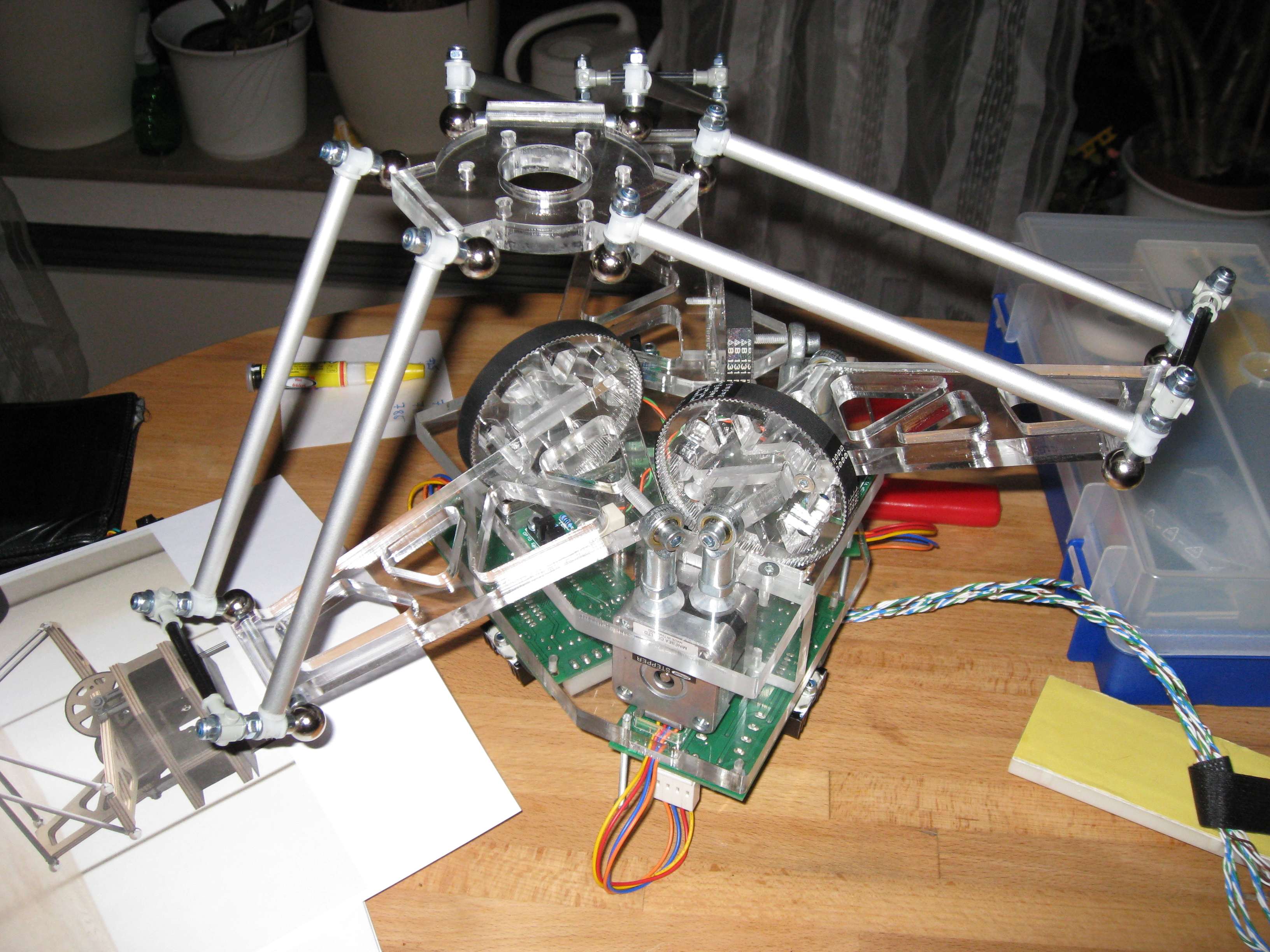
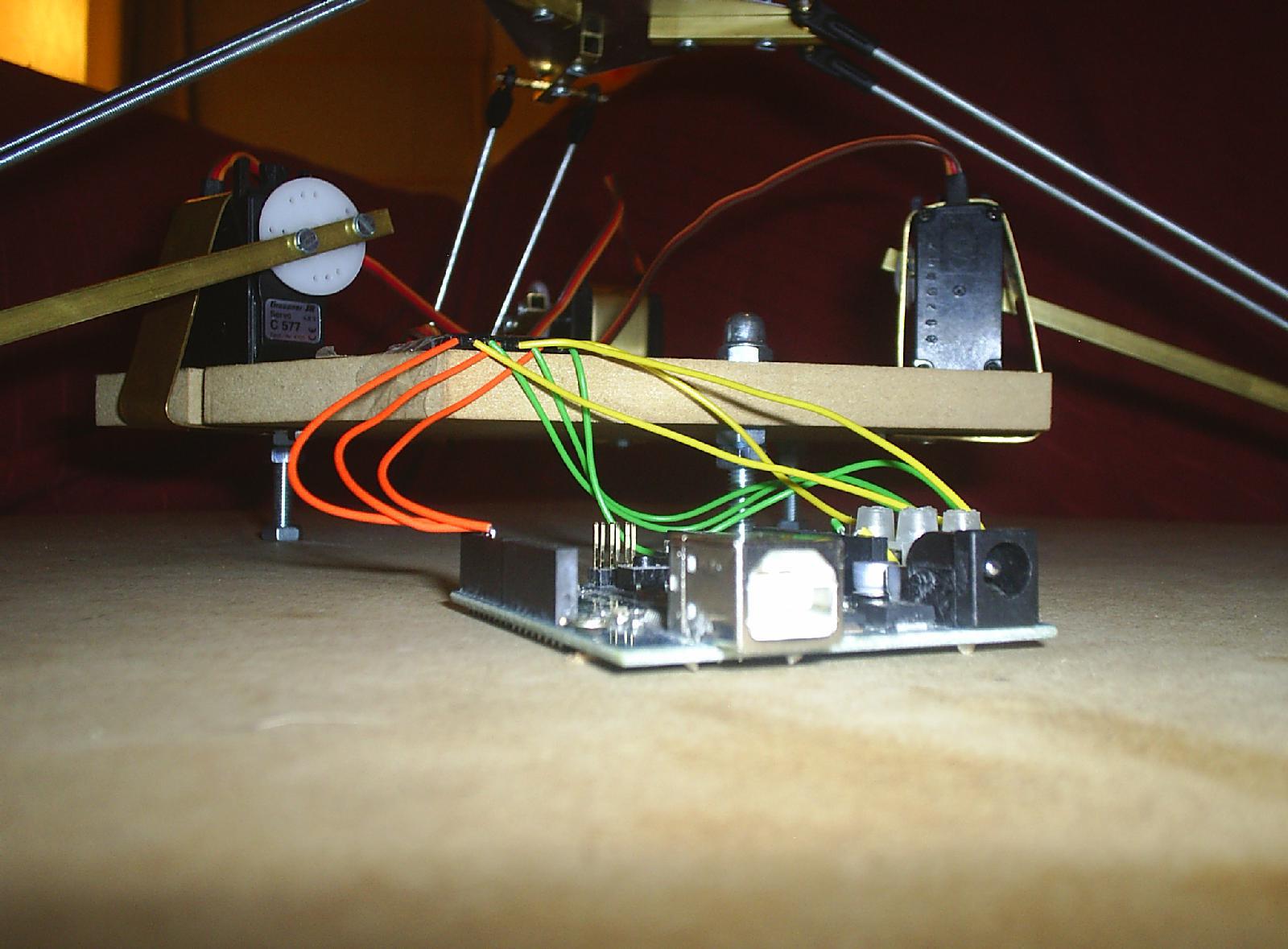
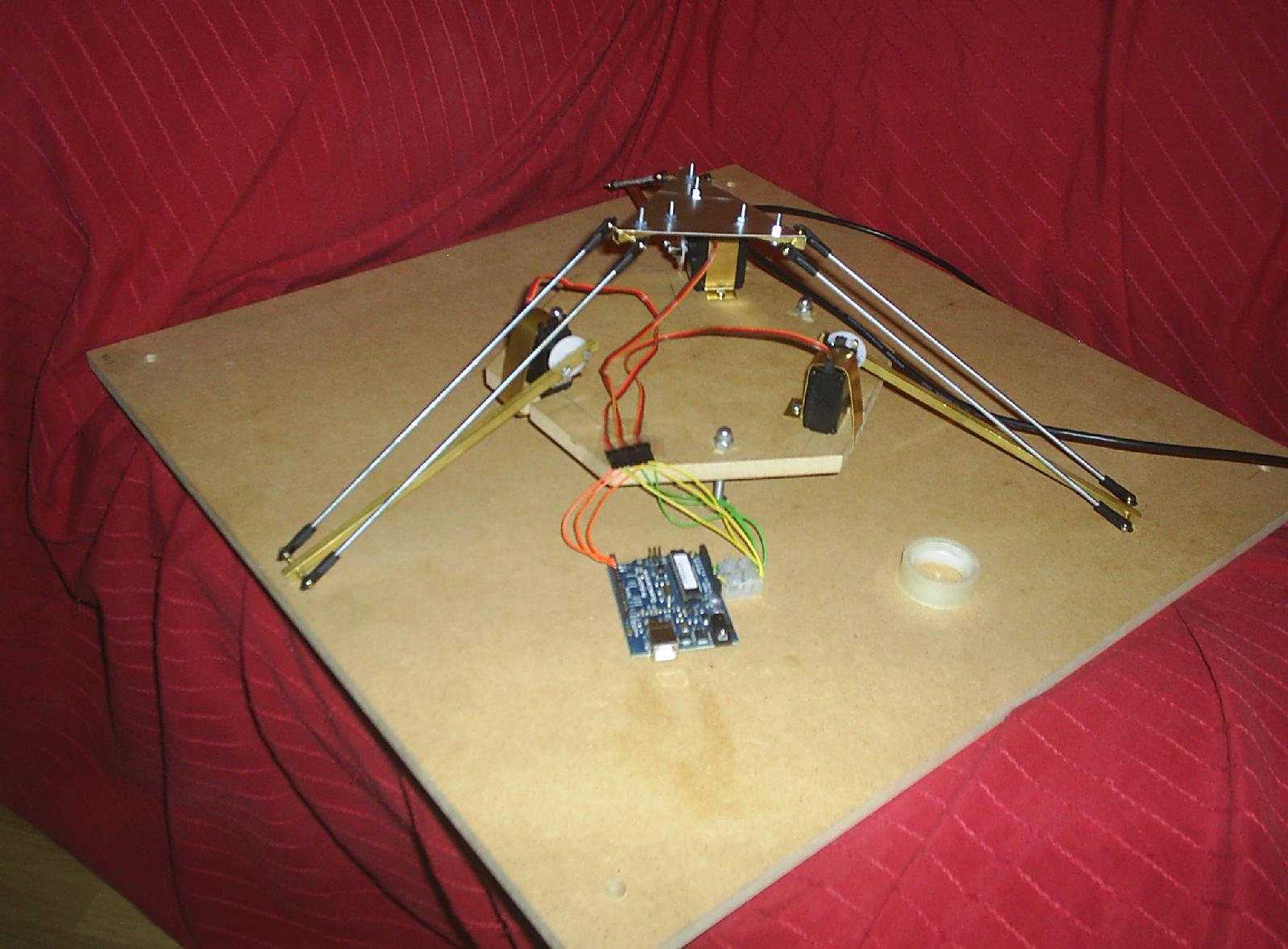
i've attached two photo's of my current prototype. I originally designed this prototype to be a poof-of-concept one; to identify the issues i need to address in the 2nd prototype and, if possible, to get some replicated parts
Before i started building i wrote a program to analyze the coordinate transformation and the resulting build volume as parameters of the aspect ratio's of the varying parts. For the back and forth transformations between the coordinate systems i used an article written by an unknown author (need to look this up!) that was a better readable form of and based on the article by the probably already known Prof. Paul Zsombor-Murray.
The resulting reachable space is, obviously, not square. When drawn, it's a complex figure that in the middle consists of a triangle with outward curved lines and that tapers in towards the top and bottom to finally degenerate into three spikes at the top and the bottom. I'll see if i can make an image of it.
To find out the practical build volume, i fitted a cube building volume with the same aspect ratio as Darwin/Mendel. Since the building volume varied significantly with the chosen size parameters, i started plotting the build volume against varying size parameters of basesize, actuatorsize, upperarm and lowerarm.
What surprised me is that there is a clear optimum in relative sizes even though i've never seen it mentioned before in other texts on Delta robots i found. Although it would be nice to have the graphs here, these result in:
What i discovered y/day is that this configuration(*) is degenerate though. In its space there is a singularity (length constraint) that prevents the mechanical robot to reach certain areas and become bistable in other places. An investigation showed that my lower arm was (obviously) too short. But how long should it be? After some thinking and math i found that in general the lower arm (re) should be greater or equal to (rf + (f-e)/2) or (rf + f/5) here. This formula doesn't keep into account the fact that the arms are at an 120 degrees angle. When taken into account, (re) can also be shown to at least needing to be to greater or equal to (rf + f/10).
Not wanting to risk another failure i went for re = (rf + (f-e)/2). This resulted indeed in all positions being reachable without the singularity. Even without that big a penalty in reachable volume.
The parameters now come down to:
This results in :
Analyzing the construction and performance of the design i notice the following:
Other observations:
My `wish list' and points of improvement for the next prototype would be:
It would be nice if we could create a Wiki page on the site for this to materialize in.
For details, please ask here!; i'll try to see if i can make the code more readable and available somewhere.
When first encountering a delta-robot on a `show' this Autumn, i immediately thought about reprapping with it. The concept struck me as a cheap and relatively easy to build RepRap/RepPrep machine concept with a lot of potential. After doing the math, building this prototype, i'm still very confident in it. Together with the magnets as ball joints and other innovations it would rock.
My fears however are the stepper motors and the accompanied electronics; those complicate things and make the electronics an expensive part. We should try to investigate driving all the necessary 4 stepper motors by the single Arduino/Megaduino/Sanguino. Maybe a simple set of shift registers (one for each motor), a stepper controller and the necessary H-bridges could do?
Hopefully we'll get it up and running!
With regards,
Reinoud
P.S. the images don't have the build-plate fitted; i planned to make it detachable by drilling holes in the build plate for it to sit on the bolt-ends. This extra space is also needed for the joints.
i've attached two photo's of my current prototype. I originally designed this prototype to be a poof-of-concept one; to identify the issues i need to address in the 2nd prototype and, if possible, to get some replicated parts
Before i started building i wrote a program to analyze the coordinate transformation and the resulting build volume as parameters of the aspect ratio's of the varying parts. For the back and forth transformations between the coordinate systems i used an article written by an unknown author (need to look this up!) that was a better readable form of and based on the article by the probably already known Prof. Paul Zsombor-Murray.
The resulting reachable space is, obviously, not square. When drawn, it's a complex figure that in the middle consists of a triangle with outward curved lines and that tapers in towards the top and bottom to finally degenerate into three spikes at the top and the bottom. I'll see if i can make an image of it.
To find out the practical build volume, i fitted a cube building volume with the same aspect ratio as Darwin/Mendel. Since the building volume varied significantly with the chosen size parameters, i started plotting the build volume against varying size parameters of basesize, actuatorsize, upperarm and lowerarm.
What surprised me is that there is a clear optimum in relative sizes even though i've never seen it mentioned before in other texts on Delta robots i found. Although it would be nice to have the graphs here, these result in:
- all other sizes can be expressed as a function of the base size (f)
- the actuator size (e) should be 3/5 of the base size f
- the upper arm (rf) should be the same size as the actuator size
- the lower arm (re) should be the same size as the upper arm (*)
- the positioning error can be approximated as roughly 3/2 times the minimum angle step of the servo's.
What i discovered y/day is that this configuration(*) is degenerate though. In its space there is a singularity (length constraint) that prevents the mechanical robot to reach certain areas and become bistable in other places. An investigation showed that my lower arm was (obviously) too short. But how long should it be? After some thinking and math i found that in general the lower arm (re) should be greater or equal to (rf + (f-e)/2) or (rf + f/5) here. This formula doesn't keep into account the fact that the arms are at an 120 degrees angle. When taken into account, (re) can also be shown to at least needing to be to greater or equal to (rf + f/10).
Not wanting to risk another failure i went for re = (rf + (f-e)/2). This resulted indeed in all positions being reachable without the singularity. Even without that big a penalty in reachable volume.
The parameters now come down to:
        f  = 300
        e  = 180
        rf = 180
        re = 240
This results in :
        Base plate servo radius 86.602 (axes)
        Base plate max radius  266.603
        Hight servo above base plate 63.3107
        max force 5.83333 N, 0.594631 Kg
        min theta -19.7892, max theta 50.6042
        block 214 x 214 x 142.665 fits
        min z 168.667 (above servo axis)
        max z 311.333 (above servo axis)
        volume 6.5335 (liter)
Analyzing the construction and performance of the design i notice the following:
- The `shoulder' joint should have as little play/backlash as possible; especially tangent to the axle where it distorts the triangle axis setup. Since the resulting lateral sway of the upper arm can give serious repercussions and can even result in the actuator being forced non parallel. I experienced this even in the patched up model. I predict that having a bigger lower arm this twisting might not be possible but still will give odd results like warping/shifts etc.
- The servo i used (Groupner C577) might not be suited to the task. Even though the forward motion is reasonable smooth and precise the backwards motion is to be desired; it seems to reach the new position from below making the backward motion a bit shakey. However this might also be a servo driving problem.
- The servo i used has a plastic gearbox. This results in a noticeable and significant enough play/backlash in the `shoulder' joint. How a digital metal gearbox servo will perform i can only speculate on.
- On power down or on reprogramming the robot collapses non gracefully.
Other observations:
- The 16Mhz Arduino Duomillianove i used, can calculate approximately 500 coordinate transformations/second.
- The transformations are obviously not linear. Traversing from one coordinate to another can thus not be done by a simple interpolation between the two calculated image of angles. Intermediate coordinates need to be calculated. I am currently working on speeding this up, and the results look very promising.
- The ball-joints i used came from Conrad and are nice and perform pretty well. The maximum angles are not super but seem to be enough. The big disadvantage is that you'll need to use M2 thread-rod and M2 nuts.... they are not only pretty tiny, they are also hard to get by!
My `wish list' and points of improvement for the next prototype would be:
- When going for servo's again, use stronger metal geared servo's. The actuator piece weight is limited by the torque of the stepper motors. Using a gear on an axle with bearings to get hardly any play/backlash on the `shoulder' joint could be an option.
- The use of geared stepper motors and, like shown on this thread before, with a kind of belt or gear setup. Belts however have inherent play as have gear setups. A good alternative would be to use Faulhaber motors+gear sets but i have no idea as to the pricing and the availability oversees.
- Either printed components or laser-cut components. For the RepPrep the laser-cut acrylic plate could be handy, for the RepRap version of it printed components would rock! I think we could easily make them with PLA.
- ...
It would be nice if we could create a Wiki page on the site for this to materialize in.
For details, please ask here!; i'll try to see if i can make the code more readable and available somewhere.
When first encountering a delta-robot on a `show' this Autumn, i immediately thought about reprapping with it. The concept struck me as a cheap and relatively easy to build RepRap/RepPrep machine concept with a lot of potential. After doing the math, building this prototype, i'm still very confident in it. Together with the magnets as ball joints and other innovations it would rock.
My fears however are the stepper motors and the accompanied electronics; those complicate things and make the electronics an expensive part. We should try to investigate driving all the necessary 4 stepper motors by the single Arduino/Megaduino/Sanguino. Maybe a simple set of shift registers (one for each motor), a stepper controller and the necessary H-bridges could do?
Hopefully we'll get it up and running!
With regards,
Reinoud
P.S. the images don't have the build-plate fitted; i planned to make it detachable by drilling holes in the build plate for it to sit on the bolt-ends. This extra space is also needed for the joints.
|
Re: Delta robots January 16, 2010 05:30PM |
Registered: 15 years ago Posts: 104 |
reinoud, thanks for the info!
If you can, can you post a link or a copy of the paper you found useful?
Gears are going to be an issue no matter what material they are made with. Personally I am planning on adding a feedback loop with a camera if and when I need the extra precision. Think optical laser mouse.
With regards to the motors, I was thinking of actually counter-balancing the weight of the arms such that the motors are not under such a load. this might be easy to do, and although will increase the total inertia of the robot,would improve its stability. Most people want a fast delta robot, however my constraints are a printable robot that can handle relaxed construction methods.
|
Re: Delta robots January 17, 2010 12:17AM |
Registered: 16 years ago Posts: 1,094 |
when using servos for precision positioning of arms, remove the feedback pot from the servo body, and affix it to the most position-sensitive joint that the servo moves- this way, the servo's own electronics take care of backlash as best they can.
You can also alter the gearing ratio to decrease speed while maintaining accuracy, if you remove the stop from the last gear in the servo body so it can turn continuously. Note that the 'dead time' will remain the same, so you still can't do tiny movements.
you may need to investigate using steppers and encoders to build precision servos with a PID loop rather than hacking hobby ones with simple dead time.
springs have been used for decades to counter-balance moving arms
|
Re: Delta robots January 17, 2010 07:58AM |
Registered: 14 years ago Posts: 45 |
Dear folks,
as promised, its an article by `mzavatsky' on Trossen robotics.
`energetic', what are your parameters according to this paper? Then i can calculate the build size for you.
With regards,
Reinoud
as promised, its an article by `mzavatsky' on Trossen robotics.
`energetic', what are your parameters according to this paper? Then i can calculate the build size for you.
With regards,
Reinoud
|
Re: Delta robots January 17, 2010 10:29AM |
Registered: 14 years ago Posts: 21 |
Hey Reinoud,
thanks, build size should be 200 x 200 x 150, fitted into the non rectangular workspace, so if you could confrim, would be good.
Parameters:
radius from center endefector to tangent of ball joint axis: 40mm
radius from center baseplate to tangent of ball joint axis : 40mm
thigh length : 132mm
tibia length : 168mm
paramter choice was based on the results of Stampers Thesis for the special case manipulator and well conditioned workspace.
those parameters differ from what the trossen robotics article uses, as well Zsombor-Murray's as they have chosen a different basic parameter setup to suit the calculation via Plucker coordinates (inverse kin).
So you would need to calculate them back to ef and ee values used by Zsombor-Murray and the trossen article.
cheers,
Torsten
|
Re: Delta robots January 17, 2010 12:19PM |
Registered: 15 years ago Posts: 104 |
Link to thesis.
THESIS REPORT
Ph.D.
A Three Degree of Freedom Parallel Manipulator
with Only Translational Degrees of Freedom
by R. E. Stamper
Advisor: L-W. Tsai
Ph.D. 97-4
THESIS REPORT
Ph.D.
A Three Degree of Freedom Parallel Manipulator
with Only Translational Degrees of Freedom
by R. E. Stamper
Advisor: L-W. Tsai
Ph.D. 97-4
|
Re: Delta robots January 18, 2010 05:48AM |
Registered: 14 years ago Posts: 45 |
Hi Torsten, hi folks,
i hope i've converted the values correctly. After some tweaking with the start height of the box it resulted in :
So pretty close, but not precisely the same, so roughly 19x19x14 instead of 20x20x15. Could it be the parameters? BTW, the theta is defined to be negative below the plane of `shoulder' joint.
OTOH, maybe the PhD theses had some things not quite correct since his results were not that quite accurate with the hand measuring. Not entirely impossible though.... could most likely also be his construction.
The device envelope is a lot smaller than my construction so that's a good sign.
With regards,
Reinoud
i hope i've converted the values correctly
. After some tweaking with the start height of the box it resulted in :
        f  = 138.564
        e  = 138.564
        rf = 132
        re = 168
        Base plate servo radius  40
        Base plate max radius   172
        Height shoulder axis above base plate 72.8288
        min theta -31.5975, max theta 56.5319
        block 188 x 188 x 141 fits
        min z 94.5 (above axis)
        max z 235.5 (above axis)
        volume 4.9835 liter
So pretty close, but not precisely the same, so roughly 19x19x14 instead of 20x20x15. Could it be the parameters? BTW, the theta is defined to be negative below the plane of `shoulder' joint.
OTOH, maybe the PhD theses had some things not quite correct since his results were not that quite accurate with the hand measuring
. Not entirely impossible though.... could most likely also be his construction.The device envelope is a lot smaller than my construction so that's a good sign.
With regards,
Reinoud
|
Re: Delta robots January 18, 2010 07:11AM |
Registered: 14 years ago Posts: 21 |

|
Re: Delta robots January 18, 2010 08:02AM |
Registered: 14 years ago Posts: 45 |
Dear folks,
i've figured out the most likely reason for the shakeyness of the downward movements in my model. I think its the PID control that functions fine when its presented a force to combat to but utterly fails when presented a force that's in the way to go causing it to overshoot, correct, overshoot, correct etc... making the movement so very jerky.
With regards,
Reinoud
|
Re: Delta robots January 18, 2010 08:11AM |
Registered: 14 years ago Posts: 45 |
Dear Torsten,
phew! glad you made the estimation yourself! Nice job btw. I guess that this 19x19x14 is good enough to start with!
Now the tricky part, making smooth movements! Can you please detail the specifics of your setup? i.e. effective stepsize in degrees, aprox. weight of the upper structure (with or without extruder), maximum step speed, some inertia info about your motor and belt? How stiff is the belt? Does it have slack, or can it stretch ?
I doubt its a good idea to put the extruder motor up there in the delta; maybe the setup by Erik de Bruin would be an idea: he placed the extruder motor outside his Darwin and used a ABS/teflon tube to guide the PLA/ABS to the extruder mouth. This could also complicate things so its a hard choice!
Cheers,
Reinoud
|
Re: Delta robots January 18, 2010 10:48AM |
Registered: 14 years ago Posts: 21 |
Hi Reinoud,
yes the initial plan was to have an bowden extruder in place. The magnetic joints can hold up to 3 kg per joint but with dynamic movement there is not much of an safety margin left if putting the stepper on to the moving part.
now for details:
gear ratio is 1:8,
standard stepper with 200 steps per rev and ,5Nm holding torque,
halfstepping ( initially, different drivers and i will go for 8th step microstepping),
belt is a standard MXL belt.
all summed up i end up with 0.1125 deg per step resolution for each axis using half steps.
I target approx. 4kHz pulse frequency from the uC to start with.
I plan on using the smooth stepper algorithm from Pramod Ranade issued in embedded 4/2009 just not with an FPGA but handling the FPGA part ( much slower of course) in an ISR.
weights i need to measure first.
Cheers,
Torsten
|
Re: Delta robots January 18, 2010 10:53AM |
Registered: 14 years ago Posts: 45 |
|
Delta robots January 19, 2010 06:47AM |
Registered: 14 years ago Posts: 54 |
|
Re: Delta robots January 19, 2010 10:49AM |
Registered: 14 years ago Posts: 45 |
Hiya Torsten,
just looked at your repository in detail; you are quite far already or did you base it on an existing one?
From memory i noticed that:
- the positions are already taken in but nothing is done yet with it
- you have the motor accelerating and deaccelerating code that does nothing yet
- it is based on the Sanguino :-S ... not bad, but i dont have one :-D
So missing is the important translation from the 3D coordinate points to the scheduling of the three steppermotors in time. I'm nearly finished with this part though it doesn't take in the inertia of the system in yet. Shall i try to tackle this problem and try to integrate it? I dont know if i'll need the accelerating or deaccelerating code but i'll keep it in mind!
Also, do you think the translation by the PhD is better suited than the one of trossen robotics? I really should try to compare the results...
As for replication, could you give a complete BOM of the design? Do you think its mechanical design is good enough for now? Have you tackled the complicated drilling issue yet? I would love to have my copy here to work on!
As for the replicatorG protocol, can the `standard' reprap software create it?
Finally, if we're using a sanguino and 3 (or later 4) stepper controllers, shouldn't it be handier to have a Altera or other FPGA handle all the stepper logics? Or a Sanguino for the hard work and one Arduino for the stepper motor controller?
With regards,
Reinoud
|
Re: Delta robots January 19, 2010 05:07PM |
Registered: 14 years ago Posts: 21 |
Hey Reinoud,
everything is based on the 3G makerbot firmware, lets see how big it gets in the end and maybe it also fits on to an arduino.
There are quite a few important pieces missing, which i'm tinkering with at the moment( the really important pieces unfortunatelly, I am not really experienced in c-programming or embedded design, but i'm learning).
Stampers and the Trossen way basically do the same, just using different coordinate transformations. I think benchmarking both back to back should give us the final answer which one is quicker. The forward kinematic solution is identical, just the coordinate system is aligned differently. if you look at my collection of fwd kin formulas you notice that there X0 beeing present is the only difference.
I noticed some design flaws during assembly, which i want to correct, but the rest is ready to go. If i find time during the weekend, i will update the drawings, so you can have a go on this.
Cheers,
Torsten
Edited 2 time(s). Last edit at 01/19/2010 05:23PM by energetic.
|
Re: Delta robots January 20, 2010 07:05AM |
Registered: 14 years ago Posts: 45 |
hi Torsten,
well as others already mentioned, programming in C++ is not a good thing in embedded systems; too much overhead and most of all memory use. I'd rather transform the project into plain C, without losing the abstraction of course. Would you mind if i did?
As for the firmware design, i think a simplification would be to have the stepper motors only step at designated time deltas; the article is suggesting stepping at non discrete intervals i.e. with a high resolution timer. Maybe a kind of `copperlist' queue that tells at which time what bits should flip on a timer would reduce complexity since a path can then be pre-calculated and passed on to the bit-flipper. I'll see if this helps reduce complexity; our CPU is limited but a lot faster than you think
BTW, i've noticed that allmost all generators, i.e. the reprap host software but also skeinforge etc. are sooo bog slow (500-1000+ seconds on a 3Ghz machine). Is this `normal' ? I've worked on a slicer algorithm myself and that's operating in real-time, even for very complex objects ... maybe i'll write a host slicer one day :-)
With regards,
Reinoud
|
Re: Delta robots January 20, 2010 01:38PM |
Registered: 14 years ago Posts: 45 |
Hi Torsten,
i think i've cracked the calculation! In my simulation i have a smooth movement from a series of points with the object accelerating and deaccelerating linearly from point to point with the speed/acceleration of the motor movements taken into care. It's still embryonic as it is mostly in float and it still needs to be fitted into the firmware, but just wanted you to hear the good news
I attached a test-pattern to inspect/analyse; it consists of (a,b,c,d) indexes, one for each motor (a,b,c) to be on the next timeslice of 64 Hz (configurable) and a (d) indicating the extrusion speed in percentage. Ihe pattern sweeps a square in the full width*height and then 4 short moves. Note that it has 1076 steps and is to be played in 16.8 seconds. Total distance is nearly one meter; aprox. the 6 cm/sec i configured it for.
Also note that the jitter in the steps/64Hz in trace1.cvs is reduced to none if the 16 microstep is chosen or when the Hz is dropped to say 30 as in trace2.cvs. Since the intervals can then be timed over a bigger time-slice the accuracy increases.
How this fits with the acceleration/deacceleration code of Pramod Ranade i dont know; i don't think its needed since the object and the axis are already accelerating/deaccelerating. Left is the setting of the individual directions and programming of the three PPM's to generate the number of pulses within the 64Hz time frame.
With regards,
Reinoud
Edited 2 time(s). Last edit at 01/20/2010 02:35PM by reinoud.


Sorry, only registered users may post in this forum.