|
Re: Delta robots March 16, 2010 07:15PM |
Registered: 15 years ago Posts: 104 |
I'll be doing a write up of the delta-strap build process soon. Probably needs its own wiki page.
Double posted
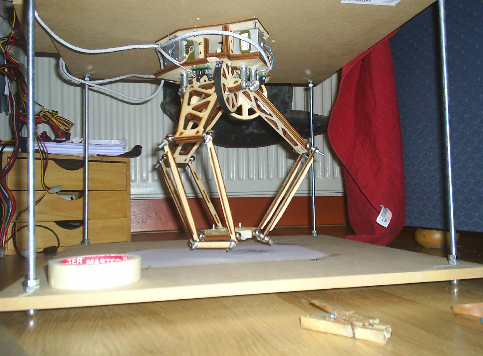
This is the mock-up image for a delta-strap, I'm building.
Its using geared stepper motors, steel tube that is going to be welded, UHMWPE cup material, rare earth magnets, and soft steel ball bearings.
I'm shooting for a build envelope of 300mm x 300mm and I'm using leg lengths of
Manipulator arm = 288.4995667241113899555444997387mm
Base arm= 135.7645019878171246849621175241mm
I went for steel because I couldn't weld aluminum, and the motors I have came with a 63/64 inch mount slug which makes interfacing with a 1 inch inner diameter steel tube fitting convenient.
The build process will be,
Because of the significant amount of hand forming this is going to require and the fact that this design is specific to one motor mount configuration, I desperately want to do a general design using standard nema motors and that use RepRapped arm segments.
Double posted

This is the mock-up image for a delta-strap, I'm building.
Its using geared stepper motors, steel tube that is going to be welded, UHMWPE cup material, rare earth magnets, and soft steel ball bearings.
I'm shooting for a build envelope of 300mm x 300mm and I'm using leg lengths of
Manipulator arm = 288.4995667241113899555444997387mm
Base arm= 135.7645019878171246849621175241mm
I went for steel because I couldn't weld aluminum, and the motors I have came with a 63/64 inch mount slug which makes interfacing with a 1 inch inner diameter steel tube fitting convenient.
The build process will be,
- Cut tube to length
- Notch tube with hole saw
- Weld tube together
- Heat plastic and stretch it so it fits in tube
- Use magnet sized heated metal plunger to form well for magnet
- Insert magnet and form plastic cup. This will be tricky because I can't heat the magnet to the working temperature of the plastic or I will destroy its magnetic properties.
- weld ball bearings to thin parallel arms
Because of the significant amount of hand forming this is going to require and the fact that this design is specific to one motor mount configuration, I desperately want to do a general design using standard nema motors and that use RepRapped arm segments.
|
Re: Delta robots April 01, 2010 01:11AM |
Registered: 15 years ago Posts: 104 |
Quick update.
So far so good. Parts came in last week and I've been working every night after work on this thing. I'll post some pictures later as I'm hoping for completion by next week.
Some corrections,
The ball bearings have to be larger. I selected 5/8 diameter bearings and I should have gone for 7/8 or 1 inch.
Also, it is nearly impossible to make perfect cuts and welds at my skill level and equipment base. That being said, this design is relatively easy to put together all things told. It beats the heck out of the Cartesian plasma robot I built.
I'm thinking I'm going to correct for physical defects in the software. This should be interesting.
|
Re: Delta robots April 02, 2010 11:13AM |
Registered: 14 years ago Posts: 28 |
energetic Wrote:
-------------------------------------------------------
> An update to my delta design. I finished the all
> laser cut design.
Hi!
I'm planning to make a Delta bot also.. my friend (Atorox) told me he might be able to cut these pieces from aluminium. Can I use your design? Would it work if cut from 3mm aluminimum?
Do you have specs for the ball joints?
I'm plannig to build the robot upside down compared to your drawing, ie. servos below and the table above the servos.
I already have a few digital servos for the project, hopefully they will suffice.
|
Re: Delta robots April 20, 2010 04:00PM |
Registered: 14 years ago Posts: 45 |
|
Re: Delta robots April 23, 2010 01:19AM |
Admin Registered: 17 years ago Posts: 1,791 |
Nice bit of work guys!
I uploaded the photo to the wiki.
[reprap.org]
(I think the page may need some cleanup.)
Again, I'm impressed with the work you've put into this.
-Sebastien, RepRap.org library gnome.
Remember, you're all RepRap developers (once you've joined the super-secret developer mailing list), and the wiki, RepRap.org, [reprap.org] is for everyone and everything!
|
Re: Delta robots May 29, 2010 04:00PM |
Registered: 14 years ago Posts: 45 |
Hi folks,
i've updated and cleaned up the Delta homepage! As for the current status: we've run into an unexpected `feature' of a belt-drive: the gear ratio of a timing belt can't be calculated the same way as with set of cogs. The exact gear ratio is unknown and can only be approximated by using the diameter ratios. So it currently needs some tinkering to get the right ratio, but we're close
Cheers,
Reinoud
|
Re: Delta robots May 30, 2010 03:45AM |
Admin Registered: 17 years ago Posts: 7,879 |
Eh? The gear ratio when using a timing belt is simply the belt pitch multiplied by the number of teeth on the pulley. The exact diameter does not need to be known and is hard to define due to the thickness of the belt.
For example, Mendel uses 5mm pitch belt and eight tooth pulleys, so one revolution is 40mm. The pulley diameter does not come into the calculation. It has to be somewhere close to correct or the belt will jump, but it does not have to be exact.
[www.hydraraptor.blogspot.com]
For example, Mendel uses 5mm pitch belt and eight tooth pulleys, so one revolution is 40mm. The pulley diameter does not come into the calculation. It has to be somewhere close to correct or the belt will jump, but it does not have to be exact.
[www.hydraraptor.blogspot.com]
|
Re: Delta robots May 30, 2010 03:24PM |
Registered: 14 years ago Posts: 45 |
Hi hophead,
that's what we thought too! The gear ratio was designed to be a factor 8, but when we used that in the Delta bot calculations we got a severely warped object. After checking off one factor at a time we came to the gear ratio; that turned out to be a lot saner when asserted around 8.5.
If the pulleys are big, the belt is locally relatively flat between two sequent sections and the multiplication of the number of teeth times pitch hold. But for small pulleys, like the one we use (16 teeth), this doesn't hold since the belt is locally not flat but curved. Since there is some tension on the belt too this means that the effective pulley is smaller. In the literature I've found on the subject they use the diameter ratio; on big pulleys this indeed is the same as the number of teeth times the pitch; but not necessarily as i showed above.
On Mendel, where the two pulleys are the same (AFAIK) the ratio is thus always 1:1 and the revolution distance is OK. But for the Delta robot the pulleys are quite different in size (16 and 128 teeth) and thus deviate. If the diameters are divided we come to just above 8.4. The real value is thus most likely around that value but measurements show its not exactly that value; we need to do additional measurements to get the right value.
With regards,
Reinoud
Edited 2 time(s). Last edit at 05/30/2010 03:34PM by reinoud.
|
Re: Delta robots May 30, 2010 04:38PM |
Registered: 15 years ago Posts: 376 |
In theory the gear ratio is just the ratio of the number of teeth ie 128/16 = 8:1. This is provided you have used gears from the same supplier and are of the same module. I had a look across the net and this seems to be the way to do it.
If something funny is happening and the gear ratio seems off, probably the best way would be to mark the motor and rotate it a set number of times by hand and calculate the movement of the output shaft.
Have you eliminated all other possibilities such as the following:-
a) Your motor drivers microstepping at different rates.
b) Mis alignment of your drive mechanisms (ie they are not at 120 degrees) or the parallel arms have not been adjusted to all be the same length. If even one of the arms is slighly off length this will cause a twisted part.
c) Your angle calculation logic is not correct. Have you built a dynamic model in CAD and moved it to known XYZ positions and measured the corresponding angles of the motors. ie. a "sanity" check of your program logic.
|
Re: Delta robots May 31, 2010 04:04AM |
Admin Registered: 17 years ago Posts: 7,879 |
Reinoud,
Timing belts have steel or Kevlar cables in them so they don't stretch. As long as the belt does not slip the teeth ratio must give the gear ratio. When an 8 tooth pulley rotates one rev it must have fed exactly 40mm of belt if the belt pitch is 5mm. Similarly if 40mm of belt passes an 8 tooth pulley it must rotate it one turn.
I don't understand your argument about small pulleys. It doesn't really matter what path the belt follows around the pulley as long as it does not slip off the teeth. That is why timing belts are called timing belts.
I have used the tooth ratio on my Mendel, including the z-axis which has different sized pulleys and the parts come out the right size.
[www.hydraraptor.blogspot.com]
|
Re: Delta robots May 31, 2010 09:36AM |
Registered: 14 years ago Posts: 45 |
Dear Martin, nophead,
That's what i thought too! BUT the gears are NOT from the same supplier. The small one and the belt are from Misumi and the large one is lasercut... the laser cut one is of the same type though, MXL, and runs smoothly over it. We also triple checked the number of teeth on both and they match. When calculating it on an online calculator it did warn us the number of teeth on the motor pulley was only 4; a bit on the low side but we never noticed slipping nor skipping. The positions are reproducible between sessions with the same vars.
As for the proposed possible problems:
a) we swapped controllers and that didn't make any difference
b) all is lasercut out. We measured them to make sure the lengths are ok and we double checked them with the model and with the firmware.
c) we performed a size estimate on both the CAD model and on the math model and they match. We also double checked the translation by calculating the results back using the reverse formula that was derived independently; they were good , within an epsilon range of course.
The distortion is very regular: when set on a factor 8.0, a grid drawn on the floor has a specific distortion. This distortion shows itself as:
- scaling: its too small and sizes are not even for the four edges; depending on the setup of the axis this can also induce non-linear scaling near the edges.
- the tip is lifted in the center as on a globe and goes down on distance from the zero point. This is a good indicator that the factor is too low. When drawing a line from (0, -Y, 0) to (0, Y, 0), i.e. along one of the arms, it gives a nice arc. Note that being to high around (0,0,0) means the angles are not big enough; not enough steps have been taken.
When the factor is set around 8.4 the distortion is nearly gone, angles near the 90 degrees, the size is approaching what it should be and the tip stays nearly level. I'd say this is surely a good indication!
What you you think?
With regards,
Reinoud
|
Re: Delta robots May 31, 2010 10:58AM |
Admin Registered: 17 years ago Posts: 7,879 |
I think you must have a software bug in the delta calculation because what you are suggesting is physically impossible. If the belt does not slip then the gear ratio MUST be in the ratio of the teeth. How could it not be? When one gear rotates by n teeth so must the other. If it did not then the belt would have to get longer and longer or shorter and shorter. Even if the teeth were slightly the wrong modulus either they would slip or bind or they would give the correct gear ratio. The belt could stretch or compress a little as it went round a pulley with the wrong diameter but there would still be a one to one correspondence between gear teeth and belt teeth unless it slips a whole tooth.
[www.hydraraptor.blogspot.com]
[www.hydraraptor.blogspot.com]
|
Re: Delta robots May 31, 2010 12:06PM |
Registered: 14 years ago Posts: 45 |
Hi nophead,
it might surprise you but i've done some new measurements and specification lookup and this is the result (pitch is 0.2032 mm) :
The big pulley has 128 teeth and thus would give a diameter of 82.79 mm. Cut out it is 82.54 mm (from DXF).
The small pulley has 16 teeth and thus would give a diameter of 10.349 for the 2.032 mm MXL pitch. However, Misumi's pulley is specified as having a diameter of 9.84 mm!
Well i don't know for sure if the bending hypothesis is correct, but i DO know that the distance traveled by the belt on the small pulley MUST be the same on the big pulley or otherwise there would be slipping and that doesn't happen due to the teeth.
Going by this, the factor is thus 1 : 82.54/9.84 = 1 : 8.388.
The assertion that the diameter of a pulley is always equal to the number of teeth times its pitch is thus falsified.
With regards,
Reinoud
Edited 1 time(s). Last edit at 05/31/2010 12:57PM by reinoud.
|
Re: Delta robots May 31, 2010 03:20PM |
Admin Registered: 17 years ago Posts: 7,879 |
The diameter and belt pitch are irrelevant (other than if they are too far out the belt will slip), it is ONLY the number of teeth that set the gear ratio, so must be 8:1 in your case. If the belt has n teeth and performs one revolution the small wheel will have turned n/16 revs and the large wheel n/128, so the large wheel will move 16/128 times slower than the small wheel, QED.
The diameter of a pulley is not the pitch times the number of teeth because the belt has finite thickness. When the belt is curled round a small pulley the belt teeth tops get closer together so the diameter for a good fit is a little less, but this is not relevant when calculating the gear ratio.
You cannot use the distance traveled because the teeth get closer together when they go round the small pulley and further apart when they go round the large pulley so your calculation involving diameters is incorrect.
[www.hydraraptor.blogspot.com]
|
Re: Delta robots June 01, 2010 02:50PM |
Registered: 14 years ago Posts: 45 |
Hi nophead,
on second thought i think I'll have to agree with you. Thanks for pointing it out to me.
It still puzzles me though why the other value gave better results... the deformity mystery only deepens... I'll dig again in the transformation code; hope it isn't a typo those are the hardest to find!
With regards,
Reinoud
on second thought i think I'll have to agree with you. Thanks for pointing it out to me.
It still puzzles me though why the other value gave better results... the deformity mystery only deepens... I'll dig again in the transformation code; hope it isn't a typo
those are the hardest to find!With regards,
Reinoud
|
Re: Delta robots June 11, 2010 04:56AM |
I have designed a DELTA robot with three degree of freedom, using CATIA and ADAMS.
The robot has three motors and the angle between them is 120.
But I can't find the relation between motors.
I need your guidance to solve my problem.
Thank you for supporting
Danialkarimi@yahoo.com
The robot has three motors and the angle between them is 120.
But I can't find the relation between motors.
I need your guidance to solve my problem.
Thank you for supporting
Danialkarimi@yahoo.com
|
Re: Delta robots July 07, 2010 10:41PM |
Hello All,
I am also endevouring to build a delta robot and seeing the progress that you guys have made over the past year has been inspiring. Given the exacting dimensions of the arms I plan on using Moldable Plastic, the stuff that melts in water and can be easily formed to create arms of exactly the same length. Since i'll be reusing the mold the arms should all even out identically. I'm hoping that will solve the deformation problems. Also I intend to use Dynamixel AX-12+ sevos to acheive some simlance of precision.
What do you guys think about the mold idea for creating the arms?
Good luck to us all!
|
Re: Delta robots July 12, 2010 09:53AM |
Registered: 14 years ago Posts: 45 |
Hi folks,
i forgot to upload the following movie i made recently of Energetics and mine Delta-Bot design proto#2. Sorry for the crappy audio but that'll have to do for now
[www.youtube.com]
We're currently in the finetuning stage of the calibration but are both crippled by simple lack of time. Nevertheless we're still working on it!
With regards,
Reinoud and Torsten
|
Re: Delta robots July 12, 2010 10:05AM |
Registered: 13 years ago Posts: 7,616 |
Looks impressive!
What's the resolution of the toolhead (how much does the toolhead move with a single step of the stepper motors)?
What's the resolution of the toolhead (how much does the toolhead move with a single step of the stepper motors)?
| Generation 7 Electronics | Teacup Firmware | RepRap DIY |
|
Re: Delta robots July 12, 2010 10:12AM |
Registered: 14 years ago Posts: 45 |
Hi Markus,
the current setup is that it should have a resolution of about 0.10 to 0.15 mm but we can get more out of it since we have spare microstepping resolution we are not using now. We could get it down to 0.02 mm but if the mechanics will show these small steps (friction, stiffness etc) we don't know yet; that's the main reason we get for 0.15 first and when we get it to work reliable we'll try to get more resolution.
With regards,
Reinoud
|
Re: Delta robots October 20, 2010 11:11AM |
Registered: 13 years ago Posts: 1,918 |
|
Re: Delta robots November 12, 2010 10:58PM |
|
Re: Delta robots November 16, 2010 03:02PM |
Registered: 14 years ago Posts: 45 |
|
Re: Delta robots November 16, 2010 03:11PM |
Registered: 14 years ago Posts: 45 |
Hi theodleif,
firmware sharing could be arranged I'm currently battling with calibration.... *sigh*. But maybe i am just too picky  I want to reach the maximum possible accuracy and maybe i should be less demanding and go for something that works first.
As for the rest of the project, Torsten is progressing nicely with the extruder design and hopefully we'll have one extruding in not so long time.
With regards and best wishes for the project,
Reinoud
firmware sharing could be arranged
I'm currently battling with calibration.... *sigh*. But maybe i am just too picky I want to reach the maximum possible accuracy and maybe i should be less demanding and go for something that works first.As for the rest of the project, Torsten is progressing nicely with the extruder design and hopefully we'll have one extruding in not so long time.
With regards and best wishes for the project,
Reinoud

Sorry, only registered users may post in this forum.