LISA Simpson
Posted by nicholas.seward
|
LISA Simpson November 16, 2013 01:59AM |
Registered: 10 years ago Posts: 979 |
vinhdinh posted about whether threaded rod could be used to make a Rostock style printer. I made a lengthy post about the reasons you wouldn't want to do that. If any of you know me then you will know that I hate to be critical. So I started to feel bad and I decided to see if I could design a decent threaded rod bot. I got a glimmer of an idea and even though it doesn't fully fit with my design asthetic I decided I had to at least mock it up. I would be delighted if someone wanted to take the idea to completion.
Design goals:
*Make a Rostock style bot that is capable of high speeds with a threaded rod.
*Minimize the number of components.
*Eliminate all spherical joints in favor of 608 bearing joints.
*Eliminate the smooth rods and linear bearings if possible.
*Look cool.
*Mount the steppers as low as possible.
*Eliminate all unnecessary supports.
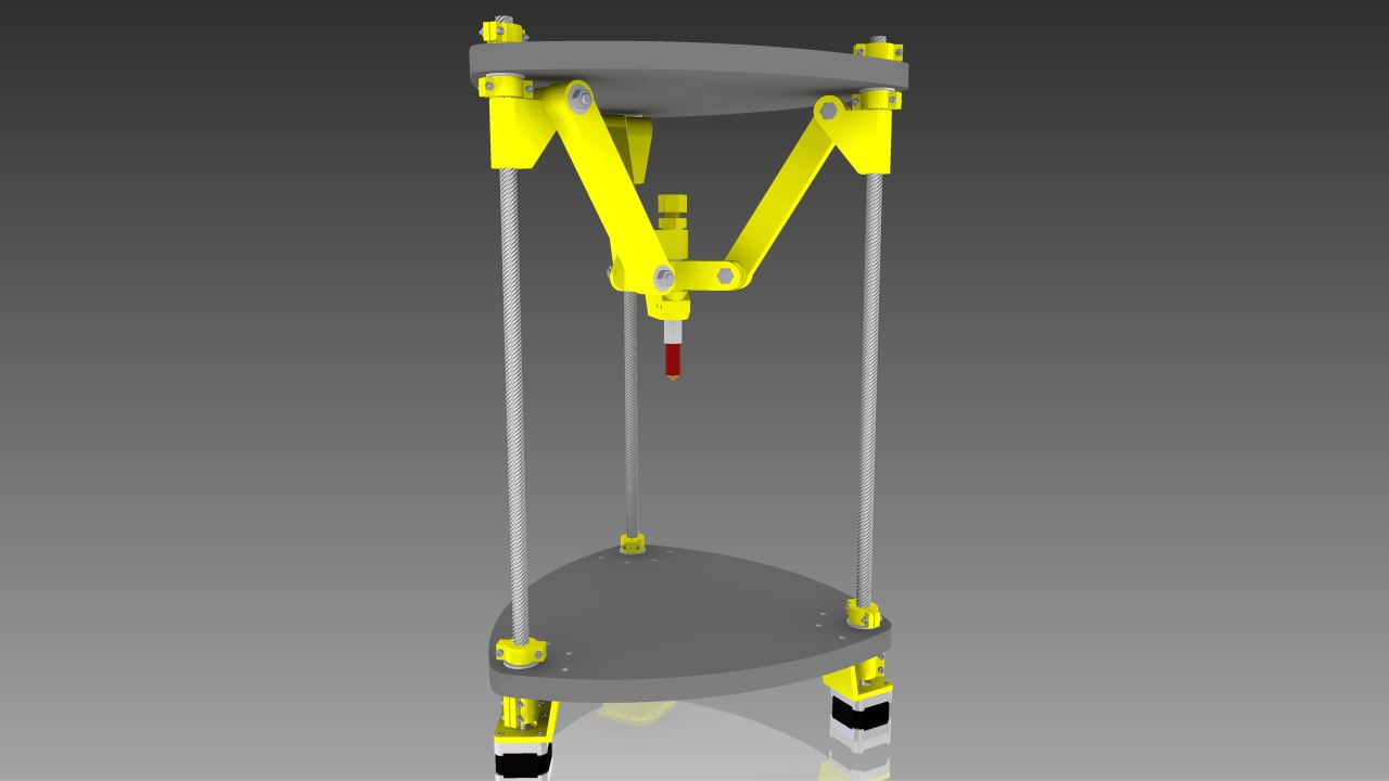
Behold LISA Simpson. (LInear Simpson Alternative) As drawn she uses 1/2"-8 8-start ACME precision ground threaded rod. I was pleasantly surprised at the price of $56. (That is not cheap but remember I got rid of all the linear rails and bearings.) This setup will move the shoulder nuts at 240mm/s. If you desire more structural stability you can upgrade to 3/4"-6 2-start rods for almost the same amount of money. (However, that upgrade will downgrade your top speed to 80mm/s.)
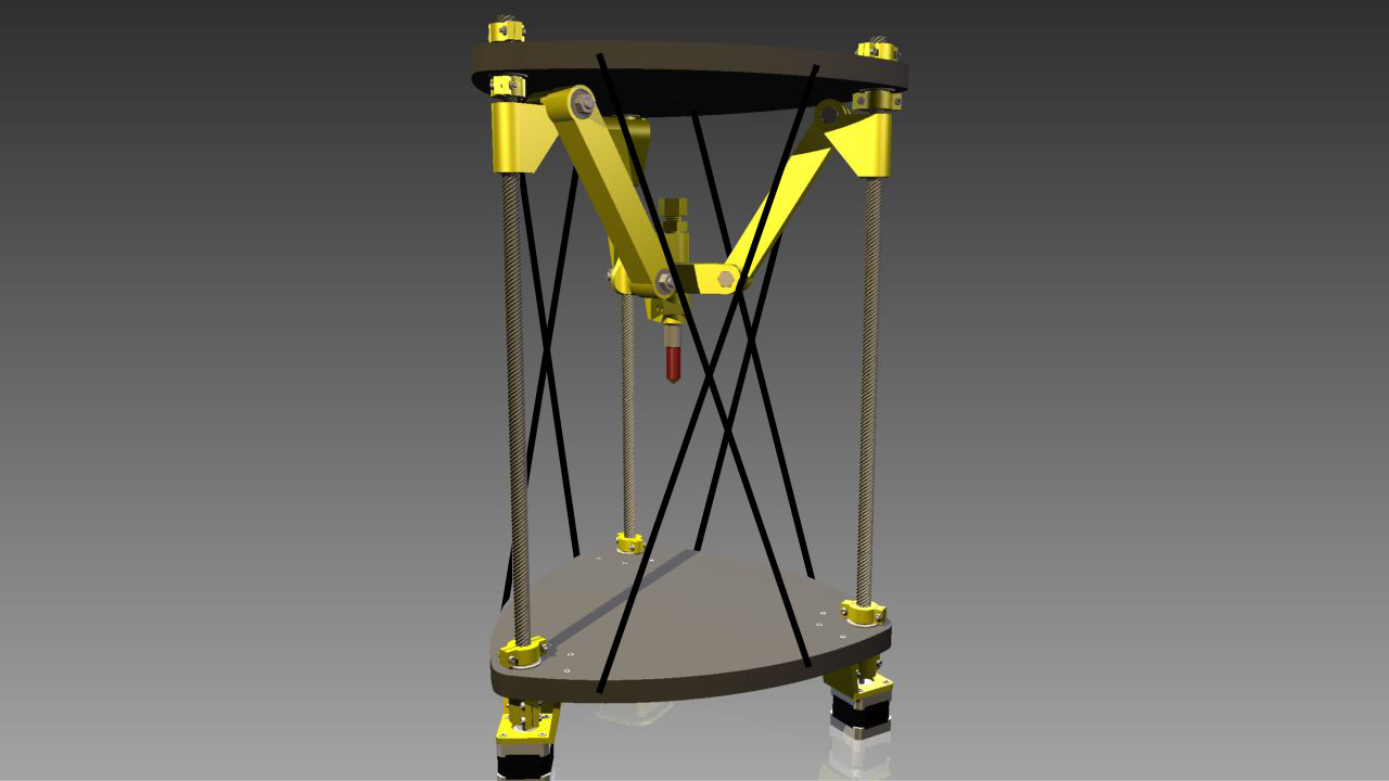
However, even with the skinnier 1/2" rods you can use some simple string to increase the rigidity of the bot. I don't see any reason to get fancier than this. I would test the rigidity without the strings first to see if the strings are even needed.
The build volume as drawn is 6L. Biggest cylinder that fits in the volume is 165mm diameter x 200mm tall.
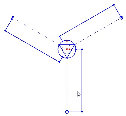
The inverse kinematics on this are pretty close to the kinematics for the Rostock. However, the carriage rotation in coupled with its translation so you will have to do one trig calculation for each arm to adjust for that. That should be no biggie for an fast ARM processor.
Rough Vitamin List:
*6' 1/2"-8 8-start ACME precision ground threaded rod $56
*12 R8ZZ bearing $34
*12 608 Bearings $3
*4 6702 Bearings $4
******* VERY LOW COST ITEMS ******
*12 M3x5
*14 M3x20
*36 M3x16
*52 M3 Nyloc Nuts
*6 M8x55
*6 M8 Nyloc Nuts
*3/4" MDF Flatstock
Concerns:
*Backlash could be a problem then again it might not. If it is, I have some ideas on how to make the printed shoulder nuts wear compensating.
*Friction. Lubrication is a must. I will need to figure out what grease is PLA safe.
Future Explorations:
*Design the hub pieces to be able to side step the threaded rod by an extra 25mm. This would give you a 50% bigger build volume. This would allow you to print a cylinder that was 210mm in diameter by 200mm tall. (Without this mod you can only print a 165x200mm cylinder.)
*Play with mounting the extruder stepper on the hub.
Edited 5 time(s). Last edit at 11/17/2013 11:39PM by nicholas.seward.
Design goals:
*Make a Rostock style bot that is capable of high speeds with a threaded rod.
*Minimize the number of components.
*Eliminate all spherical joints in favor of 608 bearing joints.
*Eliminate the smooth rods and linear bearings if possible.
*Look cool.
*Mount the steppers as low as possible.
*Eliminate all unnecessary supports.

Behold LISA Simpson. (LInear Simpson Alternative) As drawn she uses 1/2"-8 8-start ACME precision ground threaded rod. I was pleasantly surprised at the price of $56. (That is not cheap but remember I got rid of all the linear rails and bearings.) This setup will move the shoulder nuts at 240mm/s. If you desire more structural stability you can upgrade to 3/4"-6 2-start rods for almost the same amount of money. (However, that upgrade will downgrade your top speed to 80mm/s.)

However, even with the skinnier 1/2" rods you can use some simple string to increase the rigidity of the bot. I don't see any reason to get fancier than this. I would test the rigidity without the strings first to see if the strings are even needed.

The build volume as drawn is 6L. Biggest cylinder that fits in the volume is 165mm diameter x 200mm tall.
The inverse kinematics on this are pretty close to the kinematics for the Rostock. However, the carriage rotation in coupled with its translation so you will have to do one trig calculation for each arm to adjust for that. That should be no biggie for an fast ARM processor.
Rough Vitamin List:
*6' 1/2"-8 8-start ACME precision ground threaded rod $56
*12 R8ZZ bearing $34
*12 608 Bearings $3
*4 6702 Bearings $4
******* VERY LOW COST ITEMS ******
*12 M3x5
*14 M3x20
*36 M3x16
*52 M3 Nyloc Nuts
*6 M8x55
*6 M8 Nyloc Nuts
*3/4" MDF Flatstock
Concerns:
*Backlash could be a problem then again it might not. If it is, I have some ideas on how to make the printed shoulder nuts wear compensating.
*Friction. Lubrication is a must. I will need to figure out what grease is PLA safe.
Future Explorations:
*Design the hub pieces to be able to side step the threaded rod by an extra 25mm. This would give you a 50% bigger build volume. This would allow you to print a cylinder that was 210mm in diameter by 200mm tall. (Without this mod you can only print a 165x200mm cylinder.)
*Play with mounting the extruder stepper on the hub.
Edited 5 time(s). Last edit at 11/17/2013 11:39PM by nicholas.seward.
|
Re: LISA Simpson November 16, 2013 03:15AM |
Registered: 10 years ago Posts: 979 |
|
Re: LISA Simpson November 16, 2013 03:42AM |
Registered: 10 years ago Posts: 1,381 |
|
Re: LISA Simpson November 16, 2013 03:51AM |
Registered: 10 years ago Posts: 979 |
@A2: The hub is where the hot end is. If you look at the end of each of the hub stub arms you will see a cylindrical indention to allow the hub to get just a little closer to the threaded rod. If I could get the hub 25mm closer then I would have a really good build envelope. The bolt is currently in the way so I would have to L the stub arms so it can fit beside the threaded rod.
Currently, this is just a design exercise. I have no intention to build it. However, the design is almost build ready. I will throw it in my repo soon if others want to play.
I am not currently planning on doing anything with firmware. However, at some point I need to work on a generalized (not just 3DOF) gcode interpreter/inverse kinematics package for the upcoming fast ARM controllers.
|
Re: LISA Simpson November 16, 2013 04:12AM |
Registered: 10 years ago Posts: 1,381 |
|
Re: LISA Simpson November 16, 2013 04:47AM |
Registered: 10 years ago Posts: 979 |
|
Re: LISA Simpson November 16, 2013 12:43PM |
Registered: 10 years ago Posts: 1,381 |

|
Re: LISA Simpson November 16, 2013 01:32PM |
Registered: 10 years ago Posts: 25 |
Hello. Nicolas! Your idea is interesting and is always unexpected. I will try to make this design. It will be in 1-2 weeks (I now on holiday and even Wally didn't manage to finish). But brain storm it is possible now.
1 for dough it is possible to buy usual construction hairpins and long nuts (in my country of Ukraine they not expensively M10 - 1 meter about 4-5 dollar is estimated. At you likely also) and люфт won't be because weight always down.
2 if one hairpin and a hand turns it moves means that affects two others and as they on a carving they will go down or up. it needs to be compensated mathematics.
|
Re: LISA Simpson November 16, 2013 02:25PM |
Registered: 10 years ago Posts: 979 |
|
Re: LISA Simpson November 16, 2013 03:18PM |
Registered: 10 years ago Posts: 25 |
@ Nikolas. cheap hairpins only for confirmation of correctness of design. If design successful then it is possible to buy expensive hairpins. From my experience: I made long ago 3D a cutting torch where leading screws were from construction hairpins. They work perfectly till this time.
Basic racks are in any case necessary. such as here [forums.reprap.org] or similar.
Or you think you shouldn't be engaged in this design?
Basic racks are in any case necessary. such as here [forums.reprap.org] or similar.
Or you think you shouldn't be engaged in this design?
|
Re: LISA Simpson November 16, 2013 03:26PM |
Registered: 10 years ago Posts: 979 |
Quote
Vladimir_Lukashuk
@ Nikolas. cheap hairpins only for confirmation of correctness of design. If design successful then it is possible to buy expensive hairpins. From my experience: I made long ago 3D a cutting torch where leading screws were from construction hairpins. They work perfectly till this time.
Basic racks are in any case necessary. such as here [forums.reprap.org] or similar.
Or you think you shouldn't be engaged in this design?
I am not sure what you mean by basic racks but if you are refering to additional supports then I think that would not be needed. A few tensioned strings will give you plenty of rigidity if you even need them.
|
Re: LISA Simpson November 16, 2013 03:33PM |
Registered: 10 years ago Posts: 25 |
Support or strings are necessary. that's for sure. without them the design will rotate.
Strings can be taken from a bicycle wheel
Why you want to use ARM the controler?
It seems to me to make more simply a script for a python or a plug-in for slise
Edited 2 time(s). Last edit at 11/16/2013 03:50PM by Vladimir_Lukashuk.
Strings can be taken from a bicycle wheel
Why you want to use ARM the controler?
It seems to me to make more simply a script for a python or a plug-in for slise
Edited 2 time(s). Last edit at 11/16/2013 03:50PM by Vladimir_Lukashuk.
|
Re: LISA Simpson November 16, 2013 04:09PM |
Registered: 10 years ago Posts: 25 |
|
Re: LISA Simpson November 16, 2013 06:18PM |
Registered: 10 years ago Posts: 219 |
Very nice!
I am playing with a similiar construction in mind, but yet still different. I have used strings on my Rostock on two sides ( it´s a triangular base ) and they do help, yet they will not be a full replacement for the original (ugly) construction. But the strings - I used 1mm nylon - did reduce the movement of the by lets say 30%-40% and they are barely visible. You have to set up your cables and the Bowden tube very clean and short so they will not bumb into the strings. Other than that, it is a cheap and simple tweak...
From the view point of costs and simplicity, rods a very good solution, but I am afraid the trade-off will be speed. I am very curious how your project will go and rate it a two thumps up!!
Blogs:
Meine 3D Druck Abenteuer
[3dptb.blogspot.de]
FLSUN Delta Drucker für Deutschland
[flsun-deutschland.blogspot.com]
Books on 3D patents:
[goo.gl] (english)
[www.amazon.de] (deutsch)
|
Re: LISA Simpson November 16, 2013 09:59PM |
Registered: 10 years ago Posts: 1,381 |
Quote
nicholas.seward
The inverse kinematics on this are pretty close to the kinematics for the Rostock. However, the carriage rotation in coupled with its translation so you will have to do one trig calculation for each arm to adjust for that. That should be no biggie for an fast ARM processor.
I would like to start buying the components to build LISA this Monday!
But I gather there is no software to make LISA wiggle?
Or will the Rostock software work with the "L" dogleg tangent arms?
Please advise.
A2
Edited 1 time(s). Last edit at 11/16/2013 10:08PM by A2.
|
Re: LISA Simpson November 16, 2013 11:10PM |
Registered: 10 years ago Posts: 979 |
@A2: Rostock firmware will be a good enough approximation to get it to wiggle. You will be off by up to 1/6 of an inch for each carriage as you approach the outside of the envelope. However, it shouldn't be crazy hard to put the real inverse kinematics into Marlin for your version of LISA. A preprocessor may be more accessable for testing.
Good luck with the build!
Good luck with the build!
|
Re: LISA Simpson November 17, 2013 12:03AM |
Registered: 10 years ago Posts: 1,381 |

|
Re: LISA Simpson November 17, 2013 02:10AM |
Registered: 10 years ago Posts: 979 |
@Vladimir_Lukashuk: For me it is a non-issue. With well placed strings all but the most extreme prints will be trapped. In that extremely rare situation you can cut the string and remove the part. This would obviously be less than optimal if you had to print a lot of large vases. In that situation, string on two sides will be sufficient to maintain the rigidity.
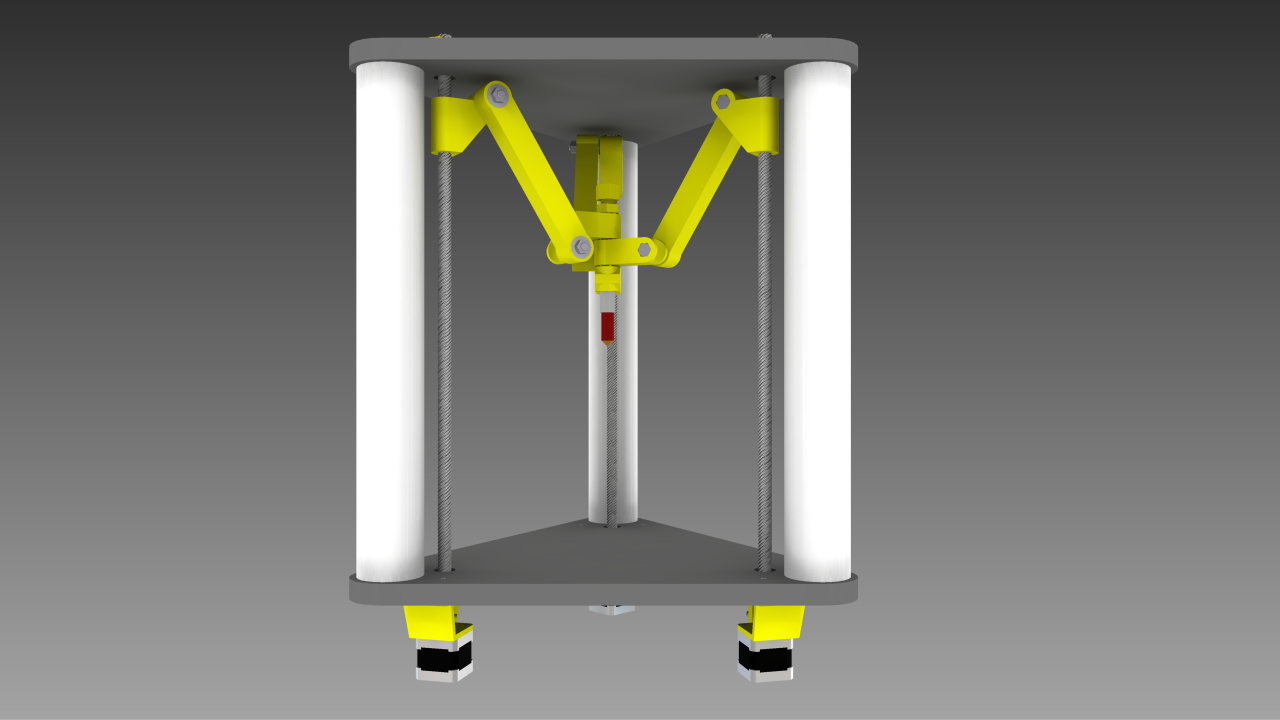
Now that I think about it, it would be nice to have 2" or 3" PVC columns (no cost) in the corners to regulate the distance between the plates. This will also allow me to remove 6 R8ZZ. This will also place the threaded rod in tension which will minimize any non-linearity present in the rod.
I think I like the PVC. It actually reduces the cost of the BOM by around $20. One side benefit is it gives you a place to run your wires to the top. As drawn it is 2" PVC which is actually 2.375" in diameter.
The bottom steppers mounts bug me for some reason. I feel like I am ignoring a more elegant solution. Any ideas?
@A2: I don't want to discourage but digging around in firmware code is almost a requirement for an experimental build such as this. I think you will find that the coordinate transformation code isn't that scary. For a example, look at the GDR code. If the math is a little inaccessible, I am sure someone in the community will not be able to control themselves. This is just too juicy of a math problem.
Edited 1 time(s). Last edit at 11/17/2013 02:12AM by nicholas.seward.
Now that I think about it, it would be nice to have 2" or 3" PVC columns (no cost) in the corners to regulate the distance between the plates. This will also allow me to remove 6 R8ZZ. This will also place the threaded rod in tension which will minimize any non-linearity present in the rod.

I think I like the PVC. It actually reduces the cost of the BOM by around $20. One side benefit is it gives you a place to run your wires to the top. As drawn it is 2" PVC which is actually 2.375" in diameter.
The bottom steppers mounts bug me for some reason. I feel like I am ignoring a more elegant solution. Any ideas?
@A2: I don't want to discourage but digging around in firmware code is almost a requirement for an experimental build such as this. I think you will find that the coordinate transformation code isn't that scary. For a example, look at the GDR code. If the math is a little inaccessible, I am sure someone in the community will not be able to control themselves. This is just too juicy of a math problem.
Edited 1 time(s). Last edit at 11/17/2013 02:12AM by nicholas.seward.
|
Re: LISA Simpson November 17, 2013 02:44AM |
Registered: 10 years ago Posts: 1,381 |
I reviewed a few kinematic terms on wikipedia, and it left me wondering what came first the chicken or the egg 
What one do you begin with?
Inverse kinematics
Forward kinematics
Kinematics chain
Kinematics pair
Quaternions (this looks like fun)
[www.youtube.com]
Is there software that can generate the code for this?
Solidus Labs code looks fairly straight forward to me.
But not having a fundamental background in kinematics I couldn't navigate this on my own.
This is my interpretation of the GDR code:
Ra_1 looks like a distance calculation.
La_1 looks like the Z axis location.
Da_1 looks like he's making the distance proportional.
Then there is a singularity check (if statements) with an alarm ECHOPGM.
Lastly he calculates the position, delta[X_AXIS].
A bit confusing as my brain thinks Cartesian coordinates when it sees XYZ, I would prefer ABC.
Where is the firmware I'll take a look at it.
I would like to see a new forum for kinematics.
A2
Edited 1 time(s). Last edit at 11/17/2013 02:45AM by A2.
|
Re: LISA Simpson November 17, 2013 02:52AM |
Registered: 10 years ago Posts: 1,381 |
|
Re: LISA Simpson November 17, 2013 04:42AM |
Registered: 10 years ago Posts: 732 |
A2:
If you use Marlin you will need to modify only one function:
Marilin_main.cpp: void calculate_delta(float cartesian[3])
This will add 3 calls to an inverse trigonometric function, some additions, and multiplies. I do not know how slow the inverse trigonometric functions are in ATmega or ARM. Maybe there is a way to get rid of them but I do not see it now.
If you will not use ARM board, you will probably need to reduce DELTA_SEGMENTS_PER_SECOND to avoid line buffer underflow (which leads to pauses in effector movement). You can go down to 70 (from original 200) if your maximum speed will be 100mm/s and diagonal rod about 200mm. In such a case the worst delta segmentation error will be below 0.01mm. In general the error is bigger when (any of):
* speed is bigger,
* delta segments per second is smaller,
* diagonal rod is smaller.
|
Re: LISA Simpson November 17, 2013 05:30AM |
Registered: 12 years ago Posts: 85 |
Could the steppers be face-down where the PVC is, with a gear to the rods?
The orientation of the steppers in this design and the open space between them could let you run (slowly) all three rods with a large gear and a single stepper motor, with a switching interface using solenoids or some other creative printed gearing/engagement/transmission mechanism. But maybe the cost is a wash vs extra vitamins/bearings.
The orientation of the steppers in this design and the open space between them could let you run (slowly) all three rods with a large gear and a single stepper motor, with a switching interface using solenoids or some other creative printed gearing/engagement/transmission mechanism. But maybe the cost is a wash vs extra vitamins/bearings.
|
Re: LISA Simpson November 17, 2013 05:40AM |
Registered: 12 years ago Posts: 85 |
Fun with kinematics:
[kinematics.wylie.su]
[soulwire.co.uk]
[www.lorenzonuvoletta.com]
[www.akjava.com]
[www.dhteumeuleu.com]
[www.andreasaristidou.com]
[www.roboticsproceedings.org]
[www.cerebralmeltdown.com]
[kinematics.wylie.su]
[soulwire.co.uk]
[www.lorenzonuvoletta.com]
[www.akjava.com]
[www.dhteumeuleu.com]
[www.andreasaristidou.com]
[www.roboticsproceedings.org]
[www.cerebralmeltdown.com]
|
Re: LISA Simpson November 17, 2013 07:42AM |
Registered: 10 years ago Posts: 219 |
You should put the steppers on top...
This will decouple them from the frame movements.
Just my 2 cents.
PS: The PVC tube idea is sweet
Edited 1 time(s). Last edit at 11/17/2013 07:43AM by maboo.
Blogs:
Meine 3D Druck Abenteuer
[3dptb.blogspot.de]
FLSUN Delta Drucker für Deutschland
[flsun-deutschland.blogspot.com]
Books on 3D patents:
[goo.gl] (english)
[www.amazon.de] (deutsch)
|
Re: LISA Simpson November 17, 2013 08:37AM |
Registered: 10 years ago Posts: 25 |
plastic pipes as support it isn't pleasant to me, they steal a place, it is simpler to make 2 solid walls and 1 door. it can be acryle or plywood or MDF a plate. who that will find, completely everything can be made only the hand saw and a drill. it as is useful for smooth heat - less delamination
|
Re: LISA Simpson November 17, 2013 11:58AM |
Registered: 12 years ago Posts: 85 |
|
Re: LISA Simpson November 17, 2013 12:05PM |
Registered: 12 years ago Posts: 85 |
How would the dynamics of supporting this machine change if the entire machine were suspended or bolted to the underside of a desk/cabinet? Maybe this is the perfect design for taking a 3' media cabinet and stacking two of these on top of eachother inside.
I have one of these MDF media cabinets that I have been thinking of converting to an enclosed printer:
[www.amazon.com]
I was thinking of a design where the steppers are outside of/on top of cabinet and it is full-height, or two units, maybe with the bottom unit having steppers underneath/outside of the cabinet. Just cut a circular hole in the bottom probably.
But it's easy to find others anywhere ..
[www.amazon.com]
[www.amazon.com]
Edited 1 time(s). Last edit at 11/17/2013 12:08PM by jason.fisher.
|
Re: LISA Simpson November 17, 2013 01:14PM |
Registered: 10 years ago Posts: 5 |
PVC might be cheaper than any kind of wall. Bottom end of PVC tube can be cutted by the diameter of the tube and pass through the bottom base. You keep the threaded rod tension, half the tube is still pressing against the base, the other half of the tube, passing through the bottom base, makes a foot for the sturcture and allow you to have each motor off the soil. I have no CAD of drawing software handy to make a draft, sorry ...
Edited 3 time(s). Last edit at 11/17/2013 01:16PM by cybug.
Edited 3 time(s). Last edit at 11/17/2013 01:16PM by cybug.
|
Re: LISA Simpson November 17, 2013 03:36PM |
Registered: 11 years ago Posts: 15 |
|
Re: LISA Simpson November 17, 2013 05:29PM |
Registered: 10 years ago Posts: 219 |
Well thats a cool idea, hide the rods inside the tube!
You just have to cut a slot into them, not even all the way, because the arms wont move all the way up and down to the bottom. That way you protect the rods from dirt etc and all that one sees moving is the arms.
Blogs:
Meine 3D Druck Abenteuer
[3dptb.blogspot.de]
FLSUN Delta Drucker für Deutschland
[flsun-deutschland.blogspot.com]
Books on 3D patents:
[goo.gl] (english)
[www.amazon.de] (deutsch)


Sorry, only registered users may post in this forum.