LISA Simpson
Posted by nicholas.seward
|
Re: LISA Simpson December 12, 2013 09:17AM |
Registered: 11 years ago Posts: 979 |
|
Re: LISA Simpson December 12, 2013 09:50AM |
Registered: 10 years ago Posts: 1,381 |
|
Re: LISA Simpson December 12, 2013 01:15PM |
Registered: 10 years ago Posts: 1,433 |
You have a bunch of "bells" (high Q metal rods) connected tightly to a nice big sounding board (the top plate). I'd be surprised if it's not got some interesting resonances.
An analogy - a tight string on a guitar makes a note when strummed. A loose un-tightened string does nothing. The under-tension lead screws are “tight strings”.
An analogy - a tight string on a guitar makes a note when strummed. A loose un-tightened string does nothing. The under-tension lead screws are “tight strings”.
|
Re: LISA Simpson December 13, 2013 10:43AM |
Registered: 10 years ago Posts: 1,381 |
@uncle_bob
I've been working on my BOM!
Of the items I have priced/estimated I'm at $688.48, and I'm probably going to add another $500.00 to it (~20% over budget).
I don't have a printer to make the plastic bits-n-bobs, so I'm forced to use Shapeways @ ($1.40/cc),
which is going to be my second biggest expense after the lead screws.
And these parts require to be custom designed just for the SLS process so they won't be good for filament printers.
I'm also going to double up on the bearings at each joint, I'm guessing that Nicholas is using 2,
(I've not yet down loaded any of his dwgs to verify), I'll be using 4 bearings at each joint.
The drawing that I want to look at are Nicholas hub drawings, as I don't have a hot end in mind to use.
Well actually I do have one hot end in mind, I plan to make a Zirconia hot end!!!
I have a laboratory kiln, she small, but she gets hot!
But I have moved, and I don't have juice to power it, or a location, got to figure some things out.
I also want to start a thread on how to make a Zirconia hot end.
I feel that some one might try to patent it, and I want to document what is not new,
what is not novel, and what one not skilled in the art would dream up for a nozzle
3 forearms 400mm each ~48 inches.
I'm leaning towards a ~Dia 1.00 inch hickory dowel, I need to visit the hardware store to see if they carry that size.
If you print custom ends that can adapt, it's your choice of what material you want to fill it in with.
Forearm mat'l:
Dia 1.00 inch Hickory.
Dia 1.00 inch Aluminum Round/Square.
Split 2x4
Closet dowel rod, big diameters can be found and long.
Cedar (burn like matches)
Steel channel used for shelving, heavy, but strong.
Are you planning on having the ends of your lead screw turned for the bearings?
I'm going to call Roton, as I need to know what tolerance they are using for the O.D. of the thread.
I want to press fit the bearings over the screw with no slop. If it's too loose then I'll probably pay to
have the ends turned down for a .750 bearing, which will blow my budget big time.
But if the screw is undersized but close, I'll take a chisel to it, and epoxy the bearing to it.
As I have minimal experience with the electronics, I want to follow your lead.
Can you provide specifications for the following, and favorite suppliers for these parts?:
Mega+Ramps version?
180w, 48v power supply?
NEMA 24?
Silicone bed heater?
LCD monitor?
SD memory card?
High current optical isolated stepper driver?
Little board for optical isolated motor drivers, what components are required?
I need a DVOM, recommendation? (I'm not counting this item in my BOM, as I've needed one for a long time)
What am I forgetting, connectors, wire, etc?
Tks!
Edited 1 time(s). Last edit at 12/13/2013 10:43AM by A2.
I've been working on my BOM!
Of the items I have priced/estimated I'm at $688.48, and I'm probably going to add another $500.00 to it (~20% over budget).
I don't have a printer to make the plastic bits-n-bobs, so I'm forced to use Shapeways @ ($1.40/cc),
which is going to be my second biggest expense after the lead screws.
And these parts require to be custom designed just for the SLS process so they won't be good for filament printers.
I'm also going to double up on the bearings at each joint, I'm guessing that Nicholas is using 2,
(I've not yet down loaded any of his dwgs to verify), I'll be using 4 bearings at each joint.
The drawing that I want to look at are Nicholas hub drawings, as I don't have a hot end in mind to use.
Well actually I do have one hot end in mind, I plan to make a Zirconia hot end!!!
I have a laboratory kiln, she small, but she gets hot!
But I have moved, and I don't have juice to power it, or a location, got to figure some things out.
I also want to start a thread on how to make a Zirconia hot end.
I feel that some one might try to patent it, and I want to document what is not new,
what is not novel, and what one not skilled in the art would dream up for a nozzle

Quote
uncle_bob
Looking at growing the LISA in X and Y - the arms grow as roughly 2/3 the screw spacing if I read right in a post above. Taking that as an accurate number, for a 600 mm screw spacing one would need 400 mm arms. Those aren't going to print easily on a common printer. Even more so if you put a skirt / brim around them to keep things flat. I'd rather not go to a pair of printed parts mated in the middle with screws, my guess is that they would not be very accurate. Some sort of aluminum bar might work, printed parts plus thread rod might work, neither gets me real excited. Am I being overly concerned here?
3 forearms 400mm each ~48 inches.
I'm leaning towards a ~Dia 1.00 inch hickory dowel, I need to visit the hardware store to see if they carry that size.
If you print custom ends that can adapt, it's your choice of what material you want to fill it in with.
Forearm mat'l:
Dia 1.00 inch Hickory.
Dia 1.00 inch Aluminum Round/Square.
Split 2x4
Closet dowel rod, big diameters can be found and long.
Cedar (burn like matches)
Steel channel used for shelving, heavy, but strong.
Are you planning on having the ends of your lead screw turned for the bearings?
I'm going to call Roton, as I need to know what tolerance they are using for the O.D. of the thread.
I want to press fit the bearings over the screw with no slop. If it's too loose then I'll probably pay to
have the ends turned down for a .750 bearing, which will blow my budget big time.
But if the screw is undersized but close, I'll take a chisel to it, and epoxy the bearing to it.
As I have minimal experience with the electronics, I want to follow your lead.
Can you provide specifications for the following, and favorite suppliers for these parts?:
Mega+Ramps version?
180w, 48v power supply?
NEMA 24?
Silicone bed heater?
LCD monitor?
SD memory card?
High current optical isolated stepper driver?
Little board for optical isolated motor drivers, what components are required?
I need a DVOM, recommendation? (I'm not counting this item in my BOM, as I've needed one for a long time)
What am I forgetting, connectors, wire, etc?
Tks!
Edited 1 time(s). Last edit at 12/13/2013 10:43AM by A2.
|
Re: LISA Simpson December 13, 2013 11:30AM |
Registered: 11 years ago Posts: 979 |
@A2: The Roton screws are undersized. The play is not enough for most application to notice. However, you can shim the screw with some paper or shim stock.
I have just recently made an experimental hub piece that will allow you to use any of the Kossel hot end mounts.
WARNING!!!!
LISA is not like your average Rostock. A normal Rostock will put each of the rods in pure compression or tension. LISA will torque the rods. Slight angular deflections can really add up. Big machines will need serious members with solid joints. Bottomline: scale up with caution. (Scale EVERYTHING proportionally. I think my proto LISA was not over engineered. I think it is right on the good side of the line.)
|
Re: LISA Simpson December 13, 2013 12:51PM |
Registered: 10 years ago Posts: 1,381 |
@nicholas.seward
OK, your warning scared me just a little, so I'm going to be careful,
and make sure we're on the same page! Tks
I don't want to waste money or have a failed project.
Do you mean the screw not being square to the lower platen, and not parallel to her sisters?
Or do you mean any unplanned rotation of the screw?
I have a machinist squares, precision protractors, and dial test indicators to
get the frame, screws, column square, parallel, etc, and a big hammer
To address unplanned rotation of the Dia 1.000" inch screw, and/or the nut,
I'm going to cast my own nuts from cerrosafe, which should have a
clearance of .0025" inch total around the screw, and 3.00" inches long nuts.
If the nut is too tight, I'll lap the nut, and add a little more clearance.
I'm also going to attempt to dust the screw with graphite before casting to give it a molded in lubricant.
I'm thinking I might use electrostatic force to adhere the graphite to the screw,
similar to how they paint auto parts in production.
Do you mean the joints in the arms, wrist, end effector?
I'm going to use Qty: 4, 608 bearings in each joint.
Or are you concerned with the long arms flexing?
Or do you mean the screw bearing pivots?
I'm going to use lead, and cast the bearings into the platens.
If they are not perfect, I can melt the lead out and recast.
I'm estimating that the complete machine will be around the 80 lbs mark so
it will be a solid desktop printer.
Or do you mean the column joint/union/connection to the upper and lower platens surfaces?
I'm going to either bolt the column, or cast lead around a metal stud to anchor them to the
upper and lower platens.
I will down load your arm and platen drawings, take measurements, then scale them.
I will measure from center line of screw to center line of end effector as the effective arm length.
And I'll measure center to center between adjacent screws.
Scaling Question:
I don't need height as much as I will use length/width (X,Y).
Target part size (1987 IBM Clicky keyboard) 8.5" x 19.25" add a 0.5" perimeter,
target print envelope (rounded) = 10" x 20".
How tall should I go, and be well within safety margins of flexing, and harmonics?
I'm not looking for anything crazy high, just a height that is proportional to the X,Y print envelope,
and proportional to the size of the Dia 1.00" screws.
If I target an 18" working print height, I'm thinking I need 28" long screws.
How does this sound to you? Would you go higher given the specs I have, or stay where I'm at?
Tks for the heads up, and I do appreciate your concern!
OK, your warning scared me just a little, so I'm going to be careful,
and make sure we're on the same page! Tks
I don't want to waste money or have a failed project.
Quote
nicholas.seward
Slight angular deflections can really add up.
Do you mean the screw not being square to the lower platen, and not parallel to her sisters?
Or do you mean any unplanned rotation of the screw?
I have a machinist squares, precision protractors, and dial test indicators to
get the frame, screws, column square, parallel, etc, and a big hammer
To address unplanned rotation of the Dia 1.000" inch screw, and/or the nut,
I'm going to cast my own nuts from cerrosafe, which should have a
clearance of .0025" inch total around the screw, and 3.00" inches long nuts.
If the nut is too tight, I'll lap the nut, and add a little more clearance.
I'm also going to attempt to dust the screw with graphite before casting to give it a molded in lubricant.
I'm thinking I might use electrostatic force to adhere the graphite to the screw,
similar to how they paint auto parts in production.
Quote
nicholas.seward
Big machines will need serious members with solid joints.
Do you mean the joints in the arms, wrist, end effector?
I'm going to use Qty: 4, 608 bearings in each joint.
Or are you concerned with the long arms flexing?
Or do you mean the screw bearing pivots?
I'm going to use lead, and cast the bearings into the platens.
If they are not perfect, I can melt the lead out and recast.
I'm estimating that the complete machine will be around the 80 lbs mark so
it will be a solid desktop printer.
Or do you mean the column joint/union/connection to the upper and lower platens surfaces?
I'm going to either bolt the column, or cast lead around a metal stud to anchor them to the
upper and lower platens.
Quote
nicholas.seward
Scale EVERYTHING proportionally.
I will down load your arm and platen drawings, take measurements, then scale them.
I will measure from center line of screw to center line of end effector as the effective arm length.
And I'll measure center to center between adjacent screws.
Scaling Question:
I don't need height as much as I will use length/width (X,Y).
Target part size (1987 IBM Clicky keyboard) 8.5" x 19.25" add a 0.5" perimeter,
target print envelope (rounded) = 10" x 20".
How tall should I go, and be well within safety margins of flexing, and harmonics?
I'm not looking for anything crazy high, just a height that is proportional to the X,Y print envelope,
and proportional to the size of the Dia 1.00" screws.
If I target an 18" working print height, I'm thinking I need 28" long screws.
How does this sound to you? Would you go higher given the specs I have, or stay where I'm at?
Tks for the heads up, and I do appreciate your concern!
|
Re: LISA Simpson December 13, 2013 02:36PM |
Registered: 10 years ago Posts: 1,381 |
I received a quote from Roton:
Dia 1.000" x 1" lead x 28.00" long:
[www.roton.com]
They charge by the whole foot, so some thing less than 3 foot, and >2 foot is charged the 3 foot price.
$83.82 - 3 foot x Qty:3 = $251.46
Shipping estimate: $22.00
Total: $273.46
Cut tolerance:
+0.125", -0.000".
No charge for cutting.
O.D. tolerance:
1.000 to 0.9965"
0.0035" range.
Hardness:
Low 20 RC (soft, like butter)
So they will rust easily, and should be protected.
|
Re: LISA Simpson December 13, 2013 02:54PM |
Registered: 11 years ago Posts: 979 |
@A2: I trust that you will make the frame rigid enough and that the screw is rigid enough using my formulas from above. With a design like this I am talking about the actual arms twisting. It doesn't take much. As a quick stab, I would suggest a 40 or 50mm square cross section of some at least as rigid as wood.
I will have to get back to you about that print volume. The design scales easier in the z direction (easier still when you scale everything up) so I will have to crank on this for a bit. I think there might be some nasty surprises for a volume of the shape you described. Hold tight or crack open a Statics text book. :-)
I will have to get back to you about that print volume. The design scales easier in the z direction (easier still when you scale everything up) so I will have to crank on this for a bit. I think there might be some nasty surprises for a volume of the shape you described. Hold tight or crack open a Statics text book. :-)
|
Re: LISA Simpson December 13, 2013 03:14PM |
Registered: 10 years ago Posts: 1,433 |
Electronics -
I have not moved into the motors and drivers stage yet. I have only looked hard enough to know that I can find something. I fully expect to try a few candidates and sort them out. On the rest of it:
Mega boards - just about any of the popular eBay suppliers will sell you a working Mega. There are a bunch of them listing stuff. Something a bit under $20 seems to be the going rate. I'd buy two while you are at it. Same thing for the Ramps 1.4 boards. $15 seems to be the going rate. GeTech (ge-th2009) is GeTech selling on eBay. They are a few bucks more, but they actually make what they are selling. I'd go for the cheaper parts and double up.
Power supplies, do not get on eBay. Get therm here in the US and get good ones. MeanWell makes good ones.
[www.trcelectronics.com]
Is one of several dealers who will sell you the real thing. The SE-350-24 and SE-450-24 are pretty good 24V fairly high current supplies. You would change the last two digits to 48 for the 48V versions. You would also want an RS-50-12 for running the fans and the Mega. There will be a little bit of wiring to do on the Ramps when you hook it all up. You can fry everything if you are not careful.
Opto driver wise, I was just going to make my own boards. They could just as easily be jumper wires. There's no electronics on them. The controllers I have seen so far all have isolating resistors in them, so they will take the 5V signals straight from the Ramps. There might be a little firmware tweak if they are not exactly right. A lot depends on the exact (and yet to be chosen) controllers.
For volt meters (DVM's), I've always liked Fluke or HP. They seem to last forever. I can't justify the price, the Chinese no name imports are cheaper and they seem to work ok. I use a Fluke 87 (or something even more exotic), but I would not buy it for this sort of stuff. The Chinese ones are around $40 or so ..
Right now on the motors, I'm headed towards NEMA-23's (which I keep calling 24's) with about 400 in-oz of torque. That should be plenty to do what ever I need to do. For a CNC - don't know. You have some loads there that a printer does not experience.
|
Re: LISA Simpson December 13, 2013 03:43PM |
Registered: 10 years ago Posts: 1,433 |
Structure-
Adding plywood to the mix (double plates of 3/4") is cheap and easy. Tossing some pieces of 1x1 or 2x2 Poplar in-between the sheets adds very little to the cost of the size. My guess is I'll do both if I go large. The local Home Depot will sell me solid wall PVC up to 4" diameter, so that's the smallest I'd go with. Above 4" the seem to like foam core. I suspect that stuff isn't very rigid. I'm also going to go back and take a look at aluminum extrusions.
The arms and their accuracy / strength / rigidity / ease of fabrication still is the biggest hangup I have on scaling everything at once (at least into the 2X range). Past the 2X range in X,Y,Z - there's only so much room around here. I may have to trade a case of beer for some CNC work.
I'm a bit concerned about a large machine that's heated up and dependent on wood for stability. I have a lot of empirical data on heated beds and LC plywood. That's another thing that drives me towards stiffening up the plywood plates. It also may get me to use aluminum in-between the sheets rather than Poplar.
More or less, if I can work out the arm issue:
Move the PVC pipes out to 3' (isn) apart. Scale them up to 4"
Take the overall height up to 5 feet with 4' rod (since you pay by the whole foot)
Double up the top plate with 3/4" Baltic birch
Double up the mid plate with the 3/4" Baltic birch
Fiddle the bottom to get it up off of the floor a bit
Fans on each of the steppers
Fans on each of the stepper controllers (fans are cheap)
Fan on the Ramps
Some sort of doors to keep the dogs out of the printer (2 Newfoundlands and a Lab).
Go with the 1" diameter 1 turn per inch screws
I believe that gives me close to 24" between the lead screws. I should have an 16" x 16" by 36" build envelope. (actually those were all questions ....)
The arms would need to be 16" long, which may rule out the "case of beer" CNC and take it more into the "figure out something else" range.
Now if I could just get the kid to return my plywood panel saw...
|
Re: LISA Simpson December 13, 2013 04:15PM |
Registered: 10 years ago Posts: 1,381 |
@nicholas.seward,
Arm (moment of inertia?):
OK, the arms need beefing-up!
50mm sounds like a good place to start, I'll see if I can find a piece of cedar.
It would be nice to wrap graphite over it.
I have a couple of cans of West System epoxy, and I'm looking for a project.
Tks for checking on the build volume in the XY!!
Build height:
Since there is no price difference, I'll order 36.00" inch long lead screws.
I'm reserving 4.00" inches of the screw length on either side of the platen, for a total of 8.00" inches.
The distance between platens would be 36.00" - 8.00" = 28.00" inches.
I'm subtracting 2.00" inches from the working build height to account for a hot plate, 28.00" - 2.00" = 26.00" build height.
Now that I think about it, I forgot I need to subtract for the end effector, and hot end,
I won't know until I draw it, maybe another 10.00" inches?, as I can't bring the arms flush to the upper platen,
and horizontal to each other as that would be a singularity.
26.00" - 10.00" = 16.00" build height, that works for me.
Edited 1 time(s). Last edit at 12/13/2013 06:15PM by A2.
|
Re: LISA Simpson December 13, 2013 06:12PM |
Registered: 10 years ago Posts: 1,381 |
@uncle_bob,
Tks for the spec's!
In the process of updating my BOM with all the new info!
I'm very thankful, you have mentioned quite a few items not on my BOM!
Struggling to keep budget under ~20% over, lol
Fluke 87, I used to use one, it was very reliable, miss it.
Column:
Your structure sounds very ridged.
Tall columns are bit of a design challenge.
Idea: 4x4 cedar post, steel brackets, then lash with carbon fiber tow + epoxy to the platen.
Tip: wrap the tow over a rod leaving enough slack after lashing to allow you to twist the rod tight to take up all the remaining slack,
and preload the tow, then anchor the rod in place and let cure.
“use aluminum in-between the sheets rather than Poplar.”
Or consider using s-glass (cheap and strong, compare it to carbon fiber) and epoxy.
Make a box frame from the plywood.
I also like the idea of a hollow column partially filled with sand and chemical to kill mold to dampen vibrations.
This will add some weight to the lower part of the frame, and maybe help with stability.
I underestimated my weight, est. ~130 lbs, and she only stands 3' feet tall, don't be laughing at her
My desk is a modern Steelcase design with a solid wood top, it's strong but now I'm doubting if I have the room.
The arms and their accuracy:
I'm going to be using adjustable ends.
That will allow me at final assembly (epoxy glue) to pass a rod through the bearings at each end of all the arms at the same time.
They will at least be extremely uniform, and very close to spec.
Arm Strength / rigidity:
Tough to beat wrapping epoxy + 6K carbon fiber tow around the arms.
Watch this video: he bends an aluminum tube with a 3d printed part with a little bit of carbon fiber tow, very impressive demo.
Carbon Reinforced 3-d Printing
[www.youtube.com]
Glass fiber
[en.wikipedia.org]
Carbon (fiber)
[en.wikipedia.org])
@nicholas.seward,
What do you think for mini Dremel router, don't you have NEMA 34 on your router?
400 in-oz of torque.
|
Re: LISA Simpson December 13, 2013 07:37PM |
Registered: 10 years ago Posts: 1,381 |
Quote
Dannydefe
Well, I ordered the screws today 7/16 steel , after talking to Roton they informed me that stainless steel was not available. I think the solution for me is to nickel plate for protection against rust. I can do this in my shop, it's actually quite easy.
I also inquired about the tap for the 7/16 -10 and they let me know that it was proprietary shape and that they were not going to sell it to us.
@ Nicholas I'm successfully printing part out but my question is how accurate do they have to be. The overall dimensions are good but it's very difficult getting the receptacles for the bearings to even get close to the proper diameter. (Always Undersized )
@Dannydefe,
Are you going to apply a hard nickel plate or a decorative nickel plate?
Can you provide plating specifications, so I can give your notes to a local plater?
In addition, I'm wondering if I can build up the surface a maximum of .0035" inch to allow a bearing to be press fit.
Roton said that the O.D. tolerance is: 1.0000" to 0.9965".
Roton screws, hardness: low 20 RC.
Qty:3, Dia 1.00" x 36" long lead screws.
Tks!
|
Re: LISA Simpson December 13, 2013 08:29PM |
Registered: 10 years ago Posts: 1,433 |
The Dremel or a router is going to be a *very* noisy beast on long jobs. There are air cooled variable frequency drive induction motor driven heads that apparently are a lot more quiet.
----------------
The problem with epoxy is that it keeps on drying forever and ever. It's strong, but it may not be very stable unless you get the layers just right. I've had parts do some *really* strange stuff a few years down the road due to epoxy issues.
----------------
The problem with epoxy is that it keeps on drying forever and ever. It's strong, but it may not be very stable unless you get the layers just right. I've had parts do some *really* strange stuff a few years down the road due to epoxy issues.
|
Re: LISA Simpson December 13, 2013 09:28PM |
Registered: 12 years ago Posts: 85 |
Is it worth looking into threadless ball screw designs again for cost effectiveness at this scale?
[www.thingiverse.com]
[www.youtube.com]
[www.youtube.com]
[www.thingiverse.com]
[www.youtube.com]
[www.youtube.com]
|
Re: LISA Simpson December 13, 2013 09:38PM |
Registered: 11 years ago Posts: 979 |
@jason.fisher: It is worth a look. However, I won't trust it until I build a test axis. I found a professional version and they claim that the forward pitch vs the backwards pitch are within 2% of each other. Maybe we can do better. I don't know. (They seem to be concerned with compact drives instead of accurate ones.)
From their literature...
This is why I hesitate.
From their literature...
Quote
The maximum difference in pitch for the two directions of travel is 2 %. We therefore recommend the use of positional sensors for positioning applications.
This is why I hesitate.
|
Re: LISA Simpson December 13, 2013 09:48PM |
Registered: 10 years ago Posts: 47 |
@A2
I only have the ability to do soft nickel plating . (hard nickel plating is quite toxic) I will be putting first coat of copper under the nickel, copper can be built-up as desired. I think for the initial plating we will just stick with the minimum. Remember I'm primarily looking for rust prevention.
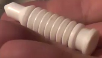
first prints
I only have the ability to do soft nickel plating . (hard nickel plating is quite toxic) I will be putting first coat of copper under the nickel, copper can be built-up as desired. I think for the initial plating we will just stick with the minimum. Remember I'm primarily looking for rust prevention.
first prints

|
Re: LISA Simpson December 14, 2013 03:45PM |
Registered: 11 years ago Posts: 979 |
Okay, I was going to try to line out the answers to a lot of the above questions but I started getting bogged down trying to organize it all. So I will boil it down to how to scale the printer.
I designed mine for a 200mm build diameter. The height is a separate issue so I will focus just on the xy scaling for now. My shoulders have a 37.5mm offset. My arms are 187.5-200mm long. My hub offset is 50mm. I list all three because you need to scale their combined length. You can scale all of them equally or just make sure you get the right combined length. Your screws are placed 1.5 build diameters apart so 300mm in my case.
Example: If you want want a 400mm build diameter, then you can just double all of the lengths above.
When you scale I would also scale your bolts, bearings, and cross section of members. (Bolts and bearings probably don't need to be scaled as much but if you go big enough you should really consider up sizing.) I use 25mm x 25mm cross sections.
Example: A 2X machine should have 50mm x 50mm cross sections.
Now for the sad part. You loose a lot of height when you arms stick down. My design wasted a significant portion of the screw. You can mount the stepper up higher and have a smooth shaft extender to maximize the usage of your screw but I don't do that in favor of simplicity. I have 24" screws and only get 10" of z travel. The 14" that I lose will scale roughly with the build diameter. So a 16" build diameter will have me sacrifice about 28" of the screw. (These are very rough ways of estimating a scale up. Drawing out your plans is the only sure way.)
And of course you need to pick the right size for your screw. Quite a few posts back I discuss the appropriate size of the screws.
@A2: Why do you want to use 4 bearings per joint? I only use 2. Do the extra 2 gain you something?
|
Re: LISA Simpson December 14, 2013 06:26PM |
Registered: 10 years ago Posts: 1,381 |
@nicholas.seward,
4 bearings/joint:
With the longer arms, wider cross section of the arm (50 mm), soft materials, offset arms, warm temperatures, the narrow width of one 608 bearing in a shallow pocket,
undersized bolt or rod, and the potential for creep over time, the bearing might rotate in it's pocket, and/or the arm could translate (shift) because of a loose fit up.
So I'm adding a bearing pocket on both sides of each of the arms in hopes to address these potential combinatorial forces.
I know that the bolt is supposed to prevent this to a large degree from happening by sandwiching the assembly together, but I want to be doubly assured.
If I don't use a printed part on the end of an arm, I'll be boring a through hole (Dia 22 mm), in that case I'll use a spacer between two bearings.
I'm being cautions, I don't want sloppy joints, I haven't started on the design, so it's all subject to change.
Tks for the notes!
Edited 1 time(s). Last edit at 12/14/2013 06:27PM by A2.
|
Re: LISA Simpson December 14, 2013 06:30PM |
Registered: 11 years ago Posts: 979 |
|
Re: LISA Simpson December 14, 2013 07:47PM |
Registered: 10 years ago Posts: 1,433 |
About the arms ...
How about printing a set of arm ends and putting them on pieces of:
[www.mcmaster.com]
Either a chunk of the square stuff, or two pieces of the round stuff. As long as it's not to massive, it's not terribly expensive. Cutting it should not be to hard with normal tools.
So:
1) nuts and bolts
2) screws
3) Glue - if so what sort?
4) taper pins
5) clamps
You could get fancy and print the clamps into the parts.
Thoughts?
|
Re: LISA Simpson December 14, 2013 07:54PM |
Registered: 11 years ago Posts: 979 |
|
Re: LISA Simpson December 14, 2013 09:16PM |
Registered: 10 years ago Posts: 1,433 |
It's the combination of zero play / all 3 same length / bearings in the same plane that I keep going through. Glue is great for zero play / not so great for adjustment. Clamps are ok for play / ok for adjustment.
I worry a bit about PVC and heat. At least when you use it for water pipe, you derate it pretty fast as the temperate goes up. I'd like to be able to heat the enclosure if needed. It seems to be something that gets done on large(r) printers. The PVC structure pipes could be outside the heated area, so they are less of an issue.
I worry a bit about PVC and heat. At least when you use it for water pipe, you derate it pretty fast as the temperate goes up. I'd like to be able to heat the enclosure if needed. It seems to be something that gets done on large(r) printers. The PVC structure pipes could be outside the heated area, so they are less of an issue.
|
Re: LISA Simpson December 14, 2013 09:18PM |
Registered: 11 years ago Posts: 979 |
|
Re: LISA Simpson December 14, 2013 09:30PM |
Registered: 10 years ago Posts: 1,433 |
I doubt I'll heat it to anything to extreme. I'd like to be able to use ABS printed parts.
It looks like:
[www.hardwarestore.com]
will glue fiberglass to ABS.
Assuming it's a machine with:
1) 24" screw spacing
2) 1" dia screws 4' long
3) fiberglass in the arms
4) ABS printed parts
How heavy does the fiberglass need to be? I'm more after an overkill number than a "just squeaks by" sort of number.
|
Re: LISA Simpson December 14, 2013 09:32PM |
Registered: 11 years ago Posts: 979 |
|
Re: LISA Simpson December 14, 2013 10:45PM |
Registered: 10 years ago Posts: 1,433 |
So if I go with the 2x2x1/4 material, it should have an ID of roughly 1.5x1.5. I could print a part with a stub on it that would mate with the end of the rectangular tube. Maybe some sort of flange as well.
Cut the fiberglass and get them all equal length. Goop up the ends with epoxy and clamp it in a fixture. Maybe just drill a couple of holes in a chunk of plywood, put in some bolts, and do them all on the same fixture. Mount the bearings in the parts first and then run the bolts through the bearings while the glue sets up. Extra nuts and washers on the bolts = clamp.
They might not all be right. They would all be wrong the same way. Do the trick with keeping track of which end and surface is which. Mount them all so same end / same surface is in the same orientation. I suspect the net result is a hot end that is not quite straight up and down. The rest of it would be binding in the bearings, and a slightly odd number to enter in the python script that translates the gcode.
Sounds like a plan.
Now ... more design or off to bed ....
1) Which bearings to use on the hub / effector?
2) How much of the existing central part of the design can be used on a bigger machine?
3) Need to scale up all the screw related stuff for 1" screws.
4) Plywood is all gang drilled, so no need for fancy stuff there.
5) Need bearings for the 1" rod.
Just a few little things to take care of.
|
Re: LISA Simpson December 14, 2013 11:16PM |
Registered: 10 years ago Posts: 1,381 |
@uncle_bob,
FRP looks good, added it to my BOM, I'm considering the steel tubing too.
$55.71, Structural Fiberglass Square Tube, 2" x 2", 1/8" Wall Thick, 10' Length
More square tubing, might be good for the arm, and column.
Check out the brackets for attaching the column:
[www.mcmaster.com]
A couple of glues to consider:
$11.93 Flexible Sealant for Plastics, 10.1-Ounce Size
operating temperature range is -75° to +350° F
[www.mcmaster.com]
$21.55, 3M 5200 Marine Adhesives/Sealants, 10-Ounce
Temperature range is -40° to +190° F.
These polyurethanes can be used to bond fiberglass (FRP) and wood.
[www.mcmaster.com]
|
Re: LISA Simpson December 15, 2013 08:56AM |
Registered: 10 years ago Posts: 1,381 |

|
Re: LISA Simpson December 15, 2013 09:42AM |
Registered: 10 years ago Posts: 1,433 |
If you haunt some of the CNC areas they spend a lot of time figuring out what is best (this week) in the world of spindles. I have not gone any deeper than simply reading along with some of it. I do know (all to well) what a carving tool sounds like compared to a "real" milling machine.
---------------------
If we are going to do this (more or less) right - deciding on things like arm materials would be a good idea. The right objective is to come up with some printable parts that others could use to build printers with. I'd like to be sure that what ever we pick is reasonable over some range of applications. The 6' printer I came up with early on is likely beyond the range of "reasonable". Defining what's reasonable is never an easy thing. It's going to be a decision each of us will make.
----------------------
Metric bolt fell off the snow blower and went who knows where, so I'm putting in a McMaster Carr order....
The "fiberglass" I came up with before is polyester material. It punks out at 140F. When I was looking, I had something a bit more sturdy in mind. G10 Garolite or G10/FR4 is what I was thinking about. That stuff is a bit more expensive. I can get 6061-T6 or 6063-T52 rectangular aluminum tube in pre-cut lengths and still stay under $50 or so as long as it's 1/8" wall. That opens up things to dimensions like 1x2 or 1.25 x 2.5. My guess is that aluminum will not not impacted by the temperatures . It also seems to be compatible with the ABS epoxies. Back to the drawing boards for the end pieces.
Edited 2 time(s). Last edit at 12/15/2013 12:51PM by uncle_bob.
---------------------
If we are going to do this (more or less) right - deciding on things like arm materials would be a good idea. The right objective is to come up with some printable parts that others could use to build printers with. I'd like to be sure that what ever we pick is reasonable over some range of applications. The 6' printer I came up with early on is likely beyond the range of "reasonable". Defining what's reasonable is never an easy thing. It's going to be a decision each of us will make.
----------------------
Metric bolt fell off the snow blower and went who knows where, so I'm putting in a McMaster Carr order....
The "fiberglass" I came up with before is polyester material. It punks out at 140F. When I was looking, I had something a bit more sturdy in mind. G10 Garolite or G10/FR4 is what I was thinking about. That stuff is a bit more expensive. I can get 6061-T6 or 6063-T52 rectangular aluminum tube in pre-cut lengths and still stay under $50 or so as long as it's 1/8" wall. That opens up things to dimensions like 1x2 or 1.25 x 2.5. My guess is that aluminum will not not impacted by the temperatures
. It also seems to be compatible with the ABS epoxies. Back to the drawing boards for the end pieces.Edited 2 time(s). Last edit at 12/15/2013 12:51PM by uncle_bob.


Sorry, only registered users may post in this forum.