LISA Simpson
Posted by nicholas.seward
|
Re: LISA Simpson January 03, 2014 06:19PM |
Registered: 10 years ago Posts: 1,433 |
|
Re: LISA Simpson January 03, 2014 09:46PM |
Registered: 10 years ago Posts: 1,381 |
Quote
uncle_bob
Scale up question:
The central axis of the machine is a hollow plastic shaft that's printed as part of hub_bottom. The shaft appears to be 15mm in diameter. I'm *guessing* that scaling up that shaft diameter would be a good idea on a 2X larger printer. 25 mm and 30 mm seem like pretty good candidates for a scale up from the standpoint of bearings to replace the 15mm 6702's.
So now the questions:
Is the shaft dimensioned based on the need to mount the hot end on the bottom or is it critical? (Do I need to scale it or not?)
If I need to scale it, is 1.5X (25mm) good enough or is 2X (30mm) the way to go?
Yes, I could go to something completely different. I'd prefer to go in as few directions at once as possible. The more I can retain from the original the better. At this point scaling is ok. Machining a different design from a solid block of tool steel - not so much.
Maybe the ubiquitous electric lamp fitting might work?
They are inexpensive, hollow, thin walled, threaded on the O.D, and are made of brass or steel.
Electric lamp fittings
[www.sizes.com]
1/4-27, Dia 6.35 mm (0.250"), 626 bearing 6x19 mm.
1/8-IP, Dia 10.29 mm, (0.405"), 6800 bearing 10x19 mm.
1/8-IP, Dia 10.29 mm, (0.405"), 6900 bearing 10x22 mm.
3/8-IP, Dia 17.15 mm, (0.675"), 6703 bearing 17x23 mm.
[www.bearingworks.com]
Edited 1 time(s). Last edit at 01/03/2014 09:49PM by A2.
|
Re: LISA Simpson January 03, 2014 10:17PM |
Registered: 10 years ago Posts: 979 |
@A2: That is great. The price is right. Here is a cheap source. [www.profhdwr.com] I am sure I will be using this for a mega Simpson. (Probably not a LISA. I am talking about a printer that can print a very roomy tent.)
|
Re: LISA Simpson January 03, 2014 11:31PM |
Registered: 10 years ago Posts: 1,433 |
OK, so what's a good cheap / easy bearing for the 1/4 IP stuff at 0.540" (13.716 mm) ? R10 or 1633 maybe?
Looks like:
[www.txlampparts.net]
Will sell you a lifetime supply of the 3/8-IP for less than $10. Looks like 3/8-ip nuts are 27 cents each at:
[www.iqlightbulbs.com]
I assume the idea is to more or less crush fit the bearings on the pipe (17 mm bearing ID and 17.14 mm pipe OD)
Edited 2 time(s). Last edit at 01/03/2014 11:44PM by uncle_bob.
|
Re: LISA Simpson January 03, 2014 11:58PM |
Registered: 10 years ago Posts: 1,381 |
@uncle_bob,
I would first try tapping it through the bearing, brass would be easier.
If that doesn't work, sand or file a little off, spin it in a drill.
[edit] A honing stone might be safer, and a more accurate method to reduce the diameter.
Don't cut your self on the sharp thin spinning threads, or get your hair, or clothing caught.
There isn't a bearing for the 13.7 mm threaded tubing, and it will be be too loose in an ID. 15.00 mm bearing.
What polymer, or filament do you have in mind that can print objects that large?
Edited 2 time(s). Last edit at 01/04/2014 02:37AM by A2.
Quote
uncle_bob
I assume the idea is to more or less crush fit the bearings on the pipe (17 mm bearing ID and 17.14 mm pipe OD)
I would first try tapping it through the bearing, brass would be easier.
If that doesn't work, sand or file a little off, spin it in a drill.
[edit] A honing stone might be safer, and a more accurate method to reduce the diameter.
Don't cut your self on the sharp thin spinning threads, or get your hair, or clothing caught.
Quote
uncle_bob
what's a good cheap / easy bearing for the 1/4 IP stuff at 0.540" (13.716 mm) ? R10 or 1633 maybe?
There isn't a bearing for the 13.7 mm threaded tubing, and it will be be too loose in an ID. 15.00 mm bearing.
Quote
nicholas.seward
I am talking about a printer that can print a very roomy tent.
What polymer, or filament do you have in mind that can print objects that large?
Edited 2 time(s). Last edit at 01/04/2014 02:37AM by A2.
|
Re: LISA Simpson January 04, 2014 12:09AM |
Registered: 10 years ago Posts: 979 |
@A2: Filing off .1mm seems reasonable. This shouldn't affect the nut.
I would have to think about it more but I would probably have plastic adapters for the bearings so you don't have to turn anything down.
I would print with a two part quick expanding foam. You could then pour concrete if you want something permanent. (Let's not sidetrack this thread with that talk. If you want to discuss this would you start a new thread and send me a PM.)
|
Re: LISA Simpson January 04, 2014 01:26AM |
Registered: 12 years ago Posts: 85 |
@A2 - Lamp rod is a fantastic idea.
I found this ceiling fan down rod that comes in multiple finishes and sizes. 3/4"x12", 1/2"x24", 3/4"x24"
Might be good sizes for a 1X or a 2X LISA? The thread also has a pin hole through it.
Edited 5 time(s). Last edit at 01/04/2014 02:35AM by jason.fisher.
I found this ceiling fan down rod that comes in multiple finishes and sizes. 3/4"x12", 1/2"x24", 3/4"x24"
Might be good sizes for a 1X or a 2X LISA? The thread also has a pin hole through it.

Edited 5 time(s). Last edit at 01/04/2014 02:35AM by jason.fisher.
|
Re: LISA Simpson January 04, 2014 03:09AM |
Registered: 10 years ago Posts: 1,381 |
Quote
nicholas.seward
I would print with a two part quick expanding foam.
I was thinking about a two part PU foam as well.
There should be an existing, inexpensive, bulk (5 gallon) two part resin available from some where.
Possibly it's being used in the automotive, commercial construction, heating & cooling, oil or mining fields.
Maybe some thing like the PU used for truck bed liners could be employed.
|
Re: LISA Simpson January 04, 2014 03:13AM |
Registered: 10 years ago Posts: 1,381 |
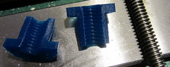
Interesting process to form a zero backlash nut, using a crush-thermoforming process.
I think it might be a better practice to heat the surface of the plastic,
don't heat the precision lead screw, it could warp or loose it's temper, (if you're not careful with the heat).
Perfect Thread ACME Flange Nuts
[www.thingiverse.com]
Edited 1 time(s). Last edit at 01/04/2014 03:14AM by A2.

I think it might be a better practice to heat the surface of the plastic,
don't heat the precision lead screw, it could warp or loose it's temper, (if you're not careful with the heat).
Perfect Thread ACME Flange Nuts
[www.thingiverse.com]
Edited 1 time(s). Last edit at 01/04/2014 03:14AM by A2.
|
Re: LISA Simpson January 04, 2014 01:31PM |
Registered: 10 years ago Posts: 1,433 |
If you go with the two part foams - keep in mind that they are a *slow* process. They also are a bit sensitive to heat and mix ratio. I once spent 4 hours with the fire crew while we tried to figure out whether facing of the top five floors of the 20 story building we had just foam filled were going to explode and rain down on the traffic in the street. Fun times ....
---------------
So - another design question:
Right now the support pipes on the LISA are on the same axis as the drive screws:
You also could rotate the supports slightly relative to the drive screws and pull them in a bit:
At some point you rotate far enough that you can no longer get the max size print out of the printer.
The advantage of rotating is that you reduce the max outer dimension of the printer by a couple inches. Getting the printer through doors and up and down stairs is the constant I'm poking at. One *might* ask what the printer is going to weigh and question the stair constraint.
On the drawings, the outer circles are the 4.5" support pipes. The inner circles are the drive shafts plus clearance. The big circle in the center is slightly larger than the max print circle. Since that circle is my print platform it's effectively >= max object footprint.

---------------
So - another design question:
Right now the support pipes on the LISA are on the same axis as the drive screws:

You also could rotate the supports slightly relative to the drive screws and pull them in a bit:
At some point you rotate far enough that you can no longer get the max size print out of the printer.
The advantage of rotating is that you reduce the max outer dimension of the printer by a couple inches. Getting the printer through doors and up and down stairs is the constant I'm poking at. One *might* ask what the printer is going to weigh and question the stair constraint.
On the drawings, the outer circles are the 4.5" support pipes. The inner circles are the drive shafts plus clearance. The big circle in the center is slightly larger than the max print circle. Since that circle is my print platform it's effectively >= max object footprint.
|
Re: LISA Simpson January 04, 2014 01:56PM |
Registered: 10 years ago Posts: 100 |
I would take a different approach (more like the thingiverse instructions). I would take a very small length of thread and dedicate it for the molding process. I would heat the thread and not the plastic. That way, most of the plastic would stay cool, except in the thread area. This should keep the plastic from shrinking or deforming while the threads cooled. The plastic welding process looks a bit tricky. It might be better to find an alternative way to hold the halves together.
It seems that a more precision way to do this would be to print the threads into the initial part, but with a little more material, and some relief lines. Then the thread only has to be barely heated to the plastic transition temp, then the part quickly clamped over the threads and a small amount of deforming of the plastic threads is all that is required for a perfect fit. If you take this approach, then it might also be possible to make the whole nut as one piece, with a "hinge" on one side and a slot "C" open on the other side. Apply some high temp silicon release to the screw. Screw the nut onto the
thread. Heat the thread. Clamp the nut. Let cool. Unclamp the nut and unscrew it. The backlash can be controlled by how tight the nut is clamped.
Quote
A2
I think it might be a better practice to heat the surface of the plastic,
don't heat the precision lead screw, it could warp or loose it's temper, (if you're not careful with the heat).
|
Re: LISA Simpson January 04, 2014 02:12PM |
Registered: 10 years ago Posts: 1,433 |
|
Re: LISA Simpson January 04, 2014 02:16PM |
Registered: 10 years ago Posts: 979 |
@uncle_bob: That is a great idea. I am going to most definetly use that idea. I saved about 100mm of the diameter of the footprint. 515mm to about 425mm

|
Re: LISA Simpson January 04, 2014 02:25PM |
Registered: 10 years ago Posts: 979 |
|
Re: LISA Simpson January 04, 2014 03:26PM |
Registered: 10 years ago Posts: 1,433 |
Ok, here's where I'm at:
Red are supports, blue are the drive shafts, purple is the clearance for a full print plate, green is the print plate. The red rectangle is the door I'd like to get through.... If it's just a door I can do a bit of carving on the base. That number may also apply to the stair rail. Have to go check.
The one thing that gets lost is the ability to put flat plates between the support pipes.
Edited 1 time(s). Last edit at 01/04/2014 03:28PM by uncle_bob.
|
Re: LISA Simpson January 04, 2014 04:21PM |
Registered: 10 years ago Posts: 979 |
[github.com]
I put these in each end of the pipe and just small holes in the flatstock so when I put all thread through everything it is all squared up.
Edited 1 time(s). Last edit at 01/04/2014 04:25PM by nicholas.seward.
I put these in each end of the pipe and just small holes in the flatstock so when I put all thread through everything it is all squared up.
Edited 1 time(s). Last edit at 01/04/2014 04:25PM by nicholas.seward.
|
Re: LISA Simpson January 04, 2014 05:15PM |
Registered: 10 years ago Posts: 1,433 |
I was wondering what that part was for ....
What you loose is the ability to easily clip plywood sheets (or what ever) to the support pipes when you want to heat the print area (or keep dogs out of it).
--------------
Is there an .xls file around that you can punch basic numbers into and get out useful information?
Inputs:
1) mounting radius of the driven shafts
2) arm length (?)
3) basic hub geometry
Outputs:
1) Print circle / square
2) optimum arm length(?)
Edited 2 time(s). Last edit at 01/04/2014 05:20PM by uncle_bob.
|
Re: LISA Simpson January 04, 2014 05:17PM |
Registered: 10 years ago Posts: 979 |
|
Re: LISA Simpson January 04, 2014 05:59PM |
Registered: 10 years ago Posts: 1,433 |
You still can come up with clips, they would not be as simple. The arms now come out past the plane between the outside of the supports.
The black circle is a guess at the real print circle. It appears to be a bit to large. I simply scaled it from the "normal" LISA. The other stuff is the same colors as the last image.
Edited 1 time(s). Last edit at 01/04/2014 06:06PM by uncle_bob.

The black circle is a guess at the real print circle. It appears to be a bit to large. I simply scaled it from the "normal" LISA. The other stuff is the same colors as the last image.
Edited 1 time(s). Last edit at 01/04/2014 06:06PM by uncle_bob.
|
Re: LISA Simpson January 04, 2014 06:01PM |
Registered: 10 years ago Posts: 979 |
|
Re: LISA Simpson January 04, 2014 06:07PM |
Registered: 10 years ago Posts: 1,433 |
|
Re: LISA Simpson January 04, 2014 06:11PM |
Registered: 12 years ago Posts: 85 |
|
Re: LISA Simpson January 04, 2014 06:20PM |
Registered: 10 years ago Posts: 1,433 |
At this point the tube isn't creating any obvious issues. Put another way, replacing it with an angle iron would not reduce the footprint.
One thing to note - The clearance areas in the drawing are not 100% correct. There is an area away from the support tube needed for arm clearance that is not shown. That would make an angle a bit harder to fit right at the corner of the triangle.
One thing to note - The clearance areas in the drawing are not 100% correct. There is an area away from the support tube needed for arm clearance that is not shown. That would make an angle a bit harder to fit right at the corner of the triangle.
|
Re: LISA Simpson January 04, 2014 09:18PM |
Registered: 10 years ago Posts: 1,381 |
Quote
jason.fisher
Would an L-shaped piece be preferable over a tube? You could line it up so the rod is partially inside of the L? Maybe like a one-piece steel bed framing piece?
I'm exploring angle stock, goal is to shorten the lead screw, the stepper motors are nested inside it, and above the printing substrate.
I don't want the motors inside the heated enclosure, using angle stock places the motors inside, I have a workaround.
A design/manufacturing challenge is to ensure that the platens are parallel, and columns are square to platens.
Must find a way to use a pen laser, mirrors, and magnets to make truing up the bot easier

I would like to find a method to replace traditional tool and die, and mold maker precision instruments,
and replace them with a pen laser.

|
Re: LISA Simpson January 04, 2014 09:50PM |
Registered: 10 years ago Posts: 1,433 |
Precision laser distance measuring involves a beam splitter a modulator and a detector in addition to the laser source. You use the reflected signal as a "resonator" in an oscillator. The period of the oscillator compared to a very accurate source gives you a distance. At < 200 mm sort of distances this gets a bit complex. The delays in the electronics begin to creep into the equation. That's the first layer to the onion.
The next layer on the onion is that you need a good target. A polished front surface mirror is fine. A piece of glass with multiple boundaries - not so much.
Next layer is - ok, I have this pile of data, how do I correct of all of it? Off to firmware land or to Python land.
Next layer - I've got a pile of data, does it relate to the printer as it is now? I've run into that one with the auto bed leveling as it exists today. The issue in my case was temperature sensitivity of the servos. The problem I was trying to fix is a temperature dependance of the plywood parts at the "couple mm over 100 mm" level.
Final layer - who knows?
------
None of that says that you can't do it. All I'm saying is that it's a pretty complicated problem.
|
Re: LISA Simpson January 04, 2014 10:04PM |
Registered: 10 years ago Posts: 1,381 |
|
Re: LISA Simpson January 04, 2014 11:48PM |
Registered: 10 years ago Posts: 1,433 |
The whole process is one where you convert this or that either to the speed of light and flight time or to phase error on fringes. To do the phase error stuff you already need to know where you are within one wavelength or it's ambiguous by that amount.
Simple answer - no free lunch. The tighter you want the accuracy to be, the more complex it gets.
There is a TI chip that will get you sub nanometer information for cheap. It needs a conductive target to work against..... (like say a big piece of cast aluminum tooling plate)
--------------
Back to figuring out where I've mucked up figuring out the head motion ....
------------
Let's say you have a magic gizmo that will give you X, Y and Z data to nanometer resolution in 10 seconds. You decide to do a survey of the volume at the 1 mm level (which may not be fine enough). You survey a normal LISA over the 200mm diameter and 250 mm height. Each layer has ~31,416 points. The survey has about 8 million points in it. It will take you about 3 years to complete the survey. A 2X larger LISA has 8X the points, so you can the same survey in a bit more time, or a lower resolution (2mm) survey in the same time. Stick with the large volume and go to a 32 mm resolution and you are back into the ~8 hour range.
Edited 4 time(s). Last edit at 01/05/2014 11:06AM by uncle_bob.
|
Re: LISA Simpson January 05, 2014 04:12PM |
Registered: 10 years ago Posts: 1,433 |

This looks like a pretty good footprint. The drive shafts are blue, the supports red. Plywood is yellowish green. Print plate is green, print area is black on top of the green.
This one fits through the doors. The print comes out of the inside no problem. The print area is almost the same as the plate. Supports are well out of the way. Looks like a winner.
Edited 2 time(s). Last edit at 01/05/2014 04:46PM by uncle_bob.
|
Re: LISA Simpson January 05, 2014 10:34PM |
Registered: 12 years ago Posts: 85 |
|
Re: LISA Simpson January 06, 2014 04:47AM |
Registered: 10 years ago Posts: 1,381 |
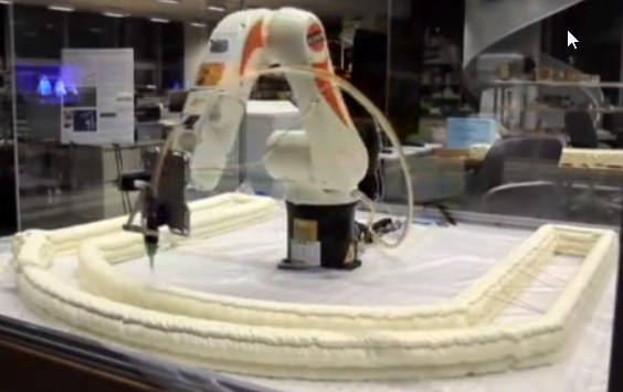
Foam printing.
Looks like AndreyR cement printer.
[forums.reprap.org]
There is a support weaving of a filament between the dual walls.
Neri Oxman
3-D printing buildings of the future
[www.youtube.com]
Neri Oxman
Is it possible to 3-D print buildings?
[www.youtube.com]
Edited 2 time(s). Last edit at 01/06/2014 04:55AM by A2.
Looks like AndreyR cement printer.
[forums.reprap.org]

There is a support weaving of a filament between the dual walls.
Neri Oxman
3-D printing buildings of the future
[www.youtube.com]
Neri Oxman
Is it possible to 3-D print buildings?
[www.youtube.com]
Edited 2 time(s). Last edit at 01/06/2014 04:55AM by A2.


Sorry, only registered users may post in this forum.