LISA Simpson
Posted by nicholas.seward
|
Re: LISA Simpson January 14, 2014 07:42AM |
Registered: 10 years ago Posts: 1,433 |
Flatness:
A lot depends on how thin a first layer you are trying to print. If I stick with something in the 0.2 to 0.3 mm thick first layer, a flatness of 0.02 mm (slightly under .001") would be ideal. Anything over 0.01" will be difficult to use. That would be a total error over the print area compared to what ever I'm calling the Z zero plane. Any bump or pit that's < 0.01" dia probably does not count .
Lapping:
Most of the home friendly approaches to lapping surfaces give you a rounded surface. I don't have the big optical flats here at home that we use at work to correct out those sort of errors. I could probably rig the monochromatic light source and the polarizer. The big slabs of optical glass - not so much.
Calibration:
You might be able to measure the plate with the printer. How you would calibrate out all the printer errors without a flat plate - not real clear. What you care about for *accuracy* then becomes an issue. I would prefer to hold the accuracy down in the 0.005" range if at all possible.
Plate Spec:
I believe that the 0.005" spec on the plate is for the "as shipped" lump of metal. I believe that lump is in the 4' wide by 10' long range. I have a lump, but not that big a lump. Since the piece has been through a lot since it left Alcoa, who knows what shape it's in now.
|
Re: LISA Simpson January 14, 2014 10:56AM |
Registered: 10 years ago Posts: 20 |
Sorry to backtrack a bit, I just finished making my delta printer, and I'm itching to make a lead screw LISA. I read through this thread but maybe I missed it. I know you guys were looking into ways to shorten the lead screws since there is a lot of wasted space. raising the stepper meant it interfered with the print area. What about mounting it on the top? More weight at the top but you can always hold the machine down at the base.
|
Re: LISA Simpson January 14, 2014 04:15PM |
Registered: 10 years ago Posts: 1,381 |
|
Re: LISA Simpson January 14, 2014 09:29PM |
Registered: 10 years ago Posts: 1,433 |
1) If you put the motors on top, you need something to terminate the short lead screws into.
2) Most of the torque and force is on the plate that has the motors and screws in common. That would mean a fairly heavy top plate.
3) If all the electronics and control are going to be closely coupled to the motors, they would go up on top as well. Same thing for the power supply.
Most of that simply makes the printer top heavy. The real issue is how to do the mount so it does not bump into the arms. Since you have a bearing and end clamp, there must be some non-zero increase over the shaft diameter. You need some sort of structure to solidly hold the bottom of the shaft. The most likely ways to do that will also increase the "bump zone" for the arms. I suspect you would have a larger bump issue this way than with the motors mounted above the lower plate.
If you put the motors on top and keep the screws full length, there's no real advantage to the top mount motors. Weight low is always better than weight up high stably wise. It's also a lot easier to get cables in and out if it's all low....
|
Re: LISA Simpson January 15, 2014 12:49AM |
Registered: 10 years ago Posts: 1,381 |

|
Re: LISA Simpson January 15, 2014 07:48AM |
Registered: 10 years ago Posts: 1,433 |
There's never a design path that's all good or all bad. The cost of the lead screws (with some thread designs) is fairly high. That can drive you to a compromise that shortens the screws. In my case it drove me to a cheaper thread design screw. That made the cost delta associated with long screws pretty minor.
No matter what you do for rods, you still have the issue of nuts. I'm doing all the attach to the rods with nuts. I'm also going with the double nut drivers. In my case the cost of the nuts is actually higher than the cost of the lead screws. Yes, you can do things on the ends a different way. That would cut the nut budget in half. With these big heavy screws, I decided the overkill approach made some amount of sense.
----
Some numbers:
3/4" shaft at 13.50 per foot. Five foot screws (in my case) x 3 needed = 15 feet total. That's $202.50 for the screws.
Nuts are $31 to $37 each depending on which ones. The minimum of three would be $93. For a dual on each driver that goes to $186. Put nuts on each end of the screws and you are at ~ $400 for nuts.
Total bill to Roton $600 or so for a big printer. Total bill with half length screws $500 or so. That's not a fair number if you shrink the printer 2:1, since you also would pull out a bunch of nuts as well. It's also not fair if you go with 1" lead 3/4" dia Torqspline at $43 a foot. Even at 7/16" Torqspline the numbers are more slanted towards the screw cost.
----
The other tradeoff (mentioned multiple times) is that the 1/2" lead probably cuts down the max speed of the printer over the 1" lead. That could be a 2:1 hit. It could be less depending on a number of things. Once the print time goes over 24 hours, what's another day waiting
Edited 1 time(s). Last edit at 01/15/2014 12:33PM by uncle_bob.
|
Re: LISA Simpson January 15, 2014 04:34PM |
Registered: 10 years ago Posts: 1,381 |
@uncle_bob:
Anti Backlash Nut
I posted about this previously, this is what it looks like:
Anti Backlash Flange Nut:
I'm thinking of ways to incorporate an anti backlash feature onto the Dia 3/4" x .50" lead screw flange nut.
It might be possible to place a tapered pipe thread on the exterior of the Roton flanged nut with a NPT 3/4" die.
A tapered pipe thread would allow you to screw on a threaded coupler to compress the thread into the lead screw to take up the backlash.
Method:
Machine a lead in angle on to the Dia. 1.125" end so a 3/4" NPT die can fit over it.
Cut threads into the O.D. of the flange nut with a pipe thread die.
Cut 1 or more narrow slot down the center of the flange nut.
Remove all internal burrs. Thermal deburring might work, but I don't know what plastic it's made of.
Screw on a metal or plastic NPT bushing, coupler, reducer, etc., to compress the flange nut into the lead screw.
[forums.reprap.org]
Edited 2 time(s). Last edit at 01/15/2014 06:25PM by A2.
Anti Backlash Nut
I posted about this previously, this is what it looks like:

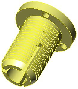
Anti Backlash Flange Nut:
I'm thinking of ways to incorporate an anti backlash feature onto the Dia 3/4" x .50" lead screw flange nut.
It might be possible to place a tapered pipe thread on the exterior of the Roton flanged nut with a NPT 3/4" die.
A tapered pipe thread would allow you to screw on a threaded coupler to compress the thread into the lead screw to take up the backlash.
Method:
Machine a lead in angle on to the Dia. 1.125" end so a 3/4" NPT die can fit over it.
Cut threads into the O.D. of the flange nut with a pipe thread die.
Cut 1 or more narrow slot down the center of the flange nut.
Remove all internal burrs. Thermal deburring might work, but I don't know what plastic it's made of.
Screw on a metal or plastic NPT bushing, coupler, reducer, etc., to compress the flange nut into the lead screw.
[forums.reprap.org]
Edited 2 time(s). Last edit at 01/15/2014 06:25PM by A2.
|
Re: LISA Simpson January 15, 2014 08:14PM |
Registered: 10 years ago Posts: 1,433 |
To really do the tension right, I suspect you need a spring to compress the cut end of the nut. With a static adjuster (like a NPT bushing) you are depending on the flex of the nut to ride out the inevitable irregular parts of the shaft. The better the spring does it's job, the less wear on the nut. Coming up with a wrap around spring that has the right spring constant could be a bit interesting ....
Maybe some sort of hose clamp over rubber foam trick ....
Edited 1 time(s). Last edit at 01/15/2014 08:17PM by uncle_bob.
Maybe some sort of hose clamp over rubber foam trick ....
Edited 1 time(s). Last edit at 01/15/2014 08:17PM by uncle_bob.
|
Re: LISA Simpson January 15, 2014 09:09PM |
Registered: 10 years ago Posts: 1,381 |
@uncle_bob:
You can make one like this, turn the OD down, machine a tapered coupler, add a coiled spring, etc:
Doesn't appear to be an anti backlash nut for the Dia .75" lead screw.
Anti-Backlash Nut, 7/16 X 1.000 Right Hand Torqspline
[www.roton.com]
Posted earlier here:
[forums.reprap.org]
Edited 1 time(s). Last edit at 01/15/2014 09:10PM by A2.
You can make one like this, turn the OD down, machine a tapered coupler, add a coiled spring, etc:

Doesn't appear to be an anti backlash nut for the Dia .75" lead screw.
Anti-Backlash Nut, 7/16 X 1.000 Right Hand Torqspline
[www.roton.com]
Posted earlier here:
[forums.reprap.org]
Edited 1 time(s). Last edit at 01/15/2014 09:10PM by A2.
|
Re: LISA Simpson January 16, 2014 07:38AM |
Registered: 12 years ago Posts: 85 |
RC suspension springs are cheap. [www.amainhobbies.com]
|
Re: LISA Simpson January 16, 2014 07:45AM |
Registered: 10 years ago Posts: 1,433 |
My guess is that you would have to play a bit with springs and tapers. The data for that nut shows they cut the load rating from 90 lb down to 25 doing what they did. That suggests they are doing some pretty major chopping on the part. Not a trivial thing to do. For a one off printer, I'm not sure you would save any money. Depending on how the rest of the printer is set up you might / might not gain some print height.
----
The other issue on the arm nuts is twist. If the drive system tips, that can rotate the effector. That gives you an error. The shorter the nut (or nut assembly) the more likely a twist is. The same sort of things that help backlash also help twist, but not always to the same degree.
----
The other issue on the arm nuts is twist. If the drive system tips, that can rotate the effector. That gives you an error. The shorter the nut (or nut assembly) the more likely a twist is. The same sort of things that help backlash also help twist, but not always to the same degree.
|
Re: LISA Simpson January 16, 2014 07:59PM |
Registered: 10 years ago Posts: 1,381 |


@uncle_bob:
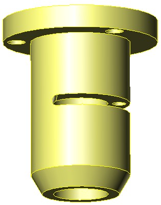
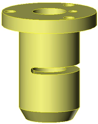
My simplest idea to eliminate backlash.
A set screw pushes apart two halves of a partially slit nut.
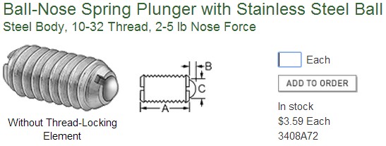
A ball nose spring plunger set screw applies a constant anti backlash force, (2 to 5 lbs force).
Additional ball nose spring plunger set screw can be added to increase the force.
You can still clamp a bracket to the OD of the nut, and use the flange.
Drawing is to scale for a 3/4 X .500 Right Hand Hi-Lead lead screw nut.
[www.roton.com]
Slit the nut.
Drill a hole in one half, and tap it (10-32), (don't drill and tap the opposite side of the slot).
Assemble a ball nose spring plunger set screw into the tapped hole.
[www.mcmaster.com]
Edited 2 time(s). Last edit at 01/16/2014 08:02PM by A2.
|
Re: LISA Simpson January 16, 2014 09:10PM |
Registered: 10 years ago Posts: 1,433 |
Ok,
The outer wall of the barrel of the flange nut to the high point in the thread is ~ 0.160". That's going by what I can measure on one sample with a dial caliper. (you might have another 0.020)
A 10-32 tap hole is 5/32 on my little chart. That's 0.156" . That's going to be a bit close.
Looks like McMaster Carr has them down to #4. That would be a 3/32" tap hole. The thread has a .112" major diameter. That would give me a total of .048" between the outer wall and the top of the tapped area. If I split it 50/50 I'd have .024" on each side. That would work in steel. I'm not so sure it's going to work in plastic. If I move the hole in, the set screw may drag on the lead screw. If I move it out, I blow out the wall of the flange nut. Either way, there's not a lot left in the wall where I drill the hole. I'm depending on the root of the threaded area to hold things together. Even with another 0.010" on each side the walls are pretty thin.
You are also down to 1/2 to 1 lb of force on the spring portion of the set screw. That's way down from the 5 lb that the #10 could have provided. I'm very sure that I have at least a few pounds of down force from the weight of the moving mass on the nut. When the hot end is right by the drive screw, there's a significant percentage of the total mass hanging on one nut. The nut (obviously) un-loads as the hot end goes to over by another drive screw. It's not one to one between the external load and the set screw spring, but I don't think 0.5 lb will do it.
...... of course I may be missing something really obvious (again)
--------
A few more numbers:
The real OD of the barrel is 1.121 +/- 0.0005. The ID is 0.639 +/- 0.0005. The flange is 0.252" thick. The OD of the flange is 1.750 +0.001 / - 0.003. The barrel is 1.754 long. The end of the barrel is square.
------------
As a rough guess, I can get a 36" build height and an 18" build circle with my 5' screws and the base layout I posted previously. That's with a double nut approach and the 1+" thick build plate mounted above the mid plate. The ends of the nuts may / may not have to run through the plywood to accomplish that.
Edited 3 time(s). Last edit at 01/16/2014 09:21PM by uncle_bob.
|
Re: LISA Simpson January 17, 2014 10:52PM |
Registered: 10 years ago Posts: 1,433 |
Math Question:
If I look at the ever popular:
1) The point that the largest circle hits the build envelope appears to be half way between the two drive shafts.
2) That's where the arm from the third drive shaft is horizontal.
3) The distance from the shaft to the hot end should be arm + hub offset + shoulder offset (unless I have those terms wrong)
4) That's 200 + 50 + 37.5 = 287.5 from the Python code
5) By calculation (in another message) the shaft is 173.2 from the center of the build area.
6) The hot end should be 287.5 - 173.2 past the center of the build area. That's 114.3 mm
7) The circle diameter should be 228.6 mm not what's shown (or ... much more likely .... I'm mixed up .... again ....)
I'm trying to check a spread sheet that I'm using for fiddling the various offsets. Either there is a number missing in the spread sheet or I can't add ....
Edited 3 time(s). Last edit at 01/17/2014 10:57PM by uncle_bob.
If I look at the ever popular:

1) The point that the largest circle hits the build envelope appears to be half way between the two drive shafts.
2) That's where the arm from the third drive shaft is horizontal.
3) The distance from the shaft to the hot end should be arm + hub offset + shoulder offset (unless I have those terms wrong)
4) That's 200 + 50 + 37.5 = 287.5 from the Python code
5) By calculation (in another message) the shaft is 173.2 from the center of the build area.
6) The hot end should be 287.5 - 173.2 past the center of the build area. That's 114.3 mm
7) The circle diameter should be 228.6 mm not what's shown (or ... much more likely .... I'm mixed up .... again ....)
I'm trying to check a spread sheet that I'm using for fiddling the various offsets. Either there is a number missing in the spread sheet or I can't add ....
Edited 3 time(s). Last edit at 01/17/2014 10:57PM by uncle_bob.
|
Re: LISA Simpson January 18, 2014 12:05AM |
Registered: 10 years ago Posts: 1,381 |
|
Re: LISA Simpson January 18, 2014 12:33AM |
Registered: 10 years ago Posts: 979 |
@uncle_bob: All that you said is correct except that the diagram was from when the shoulder offset was 25mm not 57.5mm. This extra 12.5mm adds 25mm to the build diameter.
@A2: There is no singularity when the arm is horizontal. However, you take a big speed hit there. I have done a few prints that require the arm to go almost completely horizontal and other than the speed limitations there hasn't been any problems. Hence, the actual usable circle that is 228.6mm when I was targeting 200mm. I would not blink at actually printing something that was the full 228mm.
@A2: There is no singularity when the arm is horizontal. However, you take a big speed hit there. I have done a few prints that require the arm to go almost completely horizontal and other than the speed limitations there hasn't been any problems. Hence, the actual usable circle that is 228.6mm when I was targeting 200mm. I would not blink at actually printing something that was the full 228mm.
|
Re: LISA Simpson January 18, 2014 01:55AM |
Registered: 10 years ago Posts: 1,381 |
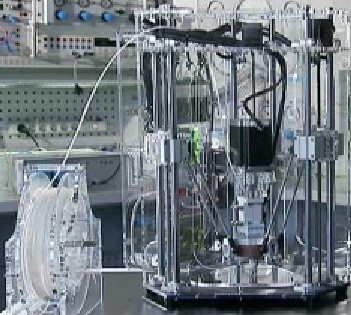
SumPod Delta 3d printer uses a lead screw.
Idea:
With the Roton Highlead lead screw and an anti rotating pickle fork attached
to the flanged nut, and the pickle fork guided by the PVC column,
you will be able to revert back to the standard delta firmware.
Advantages:
My assumption is that the original firmware can print true, and accurate squares,
and circles, otherwise this is not worth doing.
A static nut allows you to use the sturdier single shear Lisa arms, and eliminates
the flimsy magnetic ball parallelogram arms of the typical delta printer.
Method to eliminate the g-code preprocessor code:
Prevent the nut from rotating:
Use a pickle fork armature attached to the flange of the nut, and guided by the PVC column.
The column is trapped between the pickle fork, this prevents the lead screw nut from rotating.
Allow the arm to rotate about the fixed nut:
Design a sleeve with a shoulder joint with bearings that slide over the nut.
The arm is attached to the sleeve so it can rotate, and pivot up and down.
I can design the mechanics of this, but is there anything wrong with this idea from a firmware, and software point of view?
Edited 1 time(s). Last edit at 01/18/2014 01:57AM by A2.
|
Re: LISA Simpson January 18, 2014 09:44AM |
Registered: 10 years ago Posts: 1,433 |
Math:
I was going over the spread sheet back and forth figuring I'd made a really basic error. They are the ones that are very hard to spot (you missed the existence of a third arm segment). New improved smaller fits through door drawings coming soon.
Thanks!
SumPod Math:
All delta robots have the same basic issues with shape. When you want a straight line or a circle, you move all three axis at once to get the job done. That means you always have an error related to each delta axis in the resulting circle or square.
A cartesian printer has errors related to the angles between each axis. You eye does not pick these kinds of errors up as quickly. The same is true of scale errors on each axis. A circle that is *almost* the same radius the whole way around is tough to spot.
With the LISA SumPod, rotation of the smooth rods matters. With the LISA you eliminate this. No free lunch.
As soon as you add the smooth rods, the cost starts to climb. The real evaluation would have to be a "bang for the buck" sort of thing.
Speed:
As the arm goes horizontal things do slow down. With the arm's I'm using (on a big printer),you get a 1/4" radius area that things are a bit silly in. One solution would be to take the print radius from 9.5" to 9.75". The other solution would be to ignore it. How often are you going to try to print in that zone?
If you toss out the last ~ 0.9" on a 10" radius, you no longer need to traverse ~ 4" of lead screw. The longer arms to do the radius take away about 1.5" of screw (build height), so you net win back 2.5".That's only if you can play with things to still be able to use the whole screw.
Edited 5 time(s). Last edit at 01/18/2014 08:59PM by uncle_bob.
|
Re: LISA Simpson January 19, 2014 09:40AM |
Registered: 10 years ago Posts: 1,433 |
Motors:
Speed got me back to looking at the steppers that came in a while back. What came in isn't quite what the listing said it would be (welcome to auction sites ...). The motors in the listing did not have any torque vs speed curves on them. The motors I got (3A motors) *do* have torque vs speed curves. Sounds like good news....
The motors pretty much die (torque wise) at 300 rpm. Judging from the bumps and lumps in the curve, I'd guess they get into resonance issues just above that point. I also looked at another motor in the Wanti line that's very close to the 4.2 A motor I ordered. It has pretty much the same issue.
The stepper drivers seem to be good to > 100K steps/ second. That's faster than a Marlin / Ramps / Mega will do. 32 micro steps at 600 rpm is roughly 60K steps / second.
Off to look at other motors ... this time only ones with published curves ....
Why not try it and see on the assembled printer? None of these motors have the same shaft diameter or the same height. You are off to "make some adapters" land when you swap them out. If you go tall, it may be pipe cutting time.
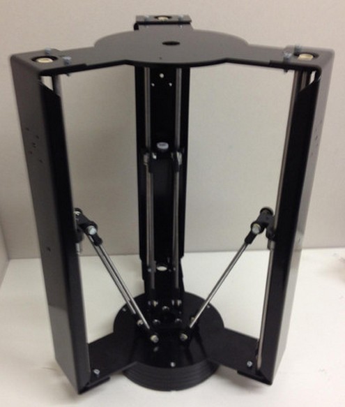
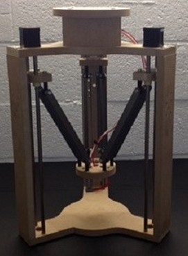
If you look at the example printers in A2's post - they all have significantly over constrained the print area and in some cases gone with very long arms to speed things up. If the arms are all < 45 degrees from vertical, speed is much less of an issue. One printer looks like it's never < 30 degrees from vertical.
Edited 2 time(s). Last edit at 01/19/2014 01:52PM by uncle_bob.
Speed got me back to looking at the steppers that came in a while back. What came in isn't quite what the listing said it would be (welcome to auction sites ...). The motors in the listing did not have any torque vs speed curves on them. The motors I got (3A motors) *do* have torque vs speed curves. Sounds like good news....
The motors pretty much die (torque wise) at 300 rpm. Judging from the bumps and lumps in the curve, I'd guess they get into resonance issues just above that point. I also looked at another motor in the Wanti line that's very close to the 4.2 A motor I ordered. It has pretty much the same issue.
The stepper drivers seem to be good to > 100K steps/ second. That's faster than a Marlin / Ramps / Mega will do. 32 micro steps at 600 rpm is roughly 60K steps / second.
Off to look at other motors ... this time only ones with published curves ....
Why not try it and see on the assembled printer? None of these motors have the same shaft diameter or the same height. You are off to "make some adapters" land when you swap them out. If you go tall, it may be pipe cutting time.
If you look at the example printers in A2's post - they all have significantly over constrained the print area and in some cases gone with very long arms to speed things up. If the arms are all < 45 degrees from vertical, speed is much less of an issue. One printer looks like it's never < 30 degrees from vertical.
Edited 2 time(s). Last edit at 01/19/2014 01:52PM by uncle_bob.
|
Re: LISA Simpson January 19, 2014 11:17PM |
Registered: 10 years ago Posts: 1,381 |
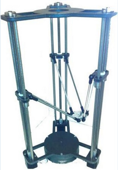
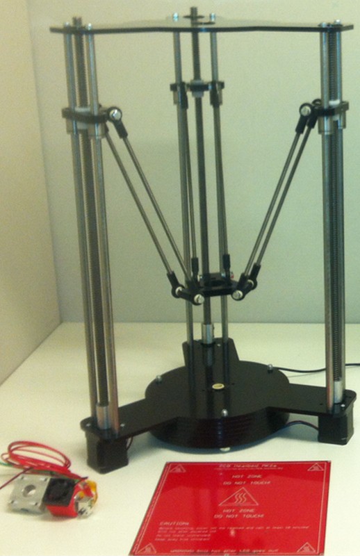
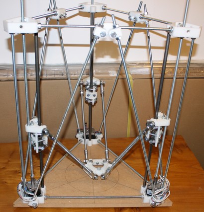
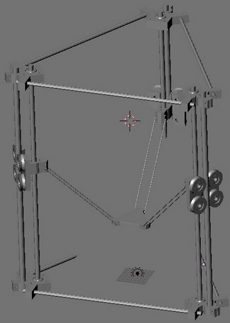
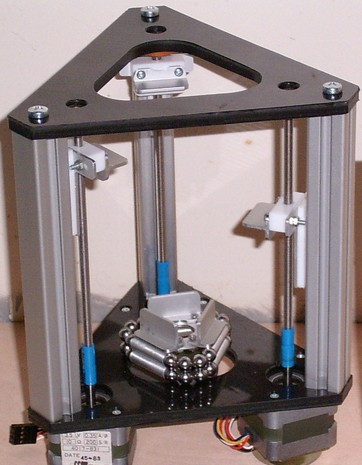
I found 4 more lead screw driven delta printers for a total of 5 not counting Lisa.
Each of these lead screw delta printers use a guide to prevent the nut from rotating, (i.e. a constrained nut).
Constrained nut advantages:
I'm assuming that these printers could replicate themselves, and
compete with the Cartesian printers on accuracy and precision of geometric shapes.
Constrained nut disadvantages:
I'm guessing that these early variants of a lead screw driven delta printer were not adopted
by the masses because the printing process was unbearably slower than a Cartesian printer.
Lisa advantages:
Utilizes a lead screw with a high rate of twist which allows parts to be manufactured at speeds comparable to a Cartesian 3d printer.
Has the ability to move a heavy mass at the end effector.
The enclosure can be heated without electronics, or stepper motors being exposed to the heat.
Low project cost to build volume size.
Easy to envision building.
Lisa disadvantages:
Lisa can't print a cube, cylinder, etc. with tolerances less than 1.0 mm for a cube, and significantly more for cylindrical objects.
Lisa is not able to replicate its self, or another RepRap 3d printer.
Question:
What solution will help Lisa to produce a more precise, and accurate geometric form? :
1. Software, (e.g. additional preprocessor g-code).
2. Constraining the nut from rotating, (e.g. a pickle fork).
Links:
Helium Frog Delta Robot
[reprap.org]
Helium Frog Delta Robot - First Steps
[www.youtube.com]
Helium Frog Delta Robot
[forums.reprap.org]
Viktor's tripod
[builders.reprap.org]
SpoonPod
[reprap.org]
[forums.reprap.org]
Festo iFab
[www.festo.com]
Edited 1 time(s). Last edit at 01/19/2014 11:19PM by A2.
Each of these lead screw delta printers use a guide to prevent the nut from rotating, (i.e. a constrained nut).
Constrained nut advantages:
I'm assuming that these printers could replicate themselves, and
compete with the Cartesian printers on accuracy and precision of geometric shapes.
Constrained nut disadvantages:
I'm guessing that these early variants of a lead screw driven delta printer were not adopted
by the masses because the printing process was unbearably slower than a Cartesian printer.


Lisa advantages:
Utilizes a lead screw with a high rate of twist which allows parts to be manufactured at speeds comparable to a Cartesian 3d printer.
Has the ability to move a heavy mass at the end effector.
The enclosure can be heated without electronics, or stepper motors being exposed to the heat.
Low project cost to build volume size.
Easy to envision building.
Lisa disadvantages:
Lisa can't print a cube, cylinder, etc. with tolerances less than 1.0 mm for a cube, and significantly more for cylindrical objects.
Lisa is not able to replicate its self, or another RepRap 3d printer.
Question:
What solution will help Lisa to produce a more precise, and accurate geometric form? :
1. Software, (e.g. additional preprocessor g-code).
2. Constraining the nut from rotating, (e.g. a pickle fork).
Links:
Helium Frog Delta Robot
[reprap.org]
Helium Frog Delta Robot - First Steps
[www.youtube.com]
Helium Frog Delta Robot
[forums.reprap.org]
Viktor's tripod
[builders.reprap.org]
SpoonPod
[reprap.org]
[forums.reprap.org]
Festo iFab
[www.festo.com]
Edited 1 time(s). Last edit at 01/19/2014 11:19PM by A2.
|
Re: LISA Simpson January 19, 2014 11:35PM |
Registered: 10 years ago Posts: 979 |
@A2: I think you have some facts wrong.
I am able to print accurate squares and round objects with much greater accuracy than 1mm. I have used it to prints parts for my GUS retrofit so I would say it is trust worthy once you have it calibrated. I would put it against almost any other printer. (Note: I have some slight screw wobble artifacts that can be addressed.)
LISA geometry is dependent on the rotating nut. This feature is an asset which aids in its simplicity. Any work to keep the nut from rotating will require many additional components that will probably cause a decrease in. accuracy. (For instance to keep the nut from rotating you would need some rails, linear bearings, and another joint with some 608 bearings so the shoulder can swivel.)
LISA can theoretically print all of her parts by design. I would probably split the arms in two because they are a bit on the long side. I will hold off on the self-replication until I build my second machine which will address some of the screw wobble issues.
There is really no reason LISA can't be squeezed in firmware. It just has to be done. It is marginally more complex than a regular column delta. However, accuracy will be the same whether you use a preprocessor or you use firmware.
|
Re: LISA Simpson January 20, 2014 12:06PM |
Registered: 10 years ago Posts: 1,433 |
Most of the Delts'a out there have universal joints in them. The tolerance / wear / wobble issues with them are well documented. Going from the fancy bearings in a LISA back to the universal joints would not improve the accuracy.
None of the Delta printers print perfect parts right out of the box. The same is true of cartesian printers. My i3 did not print perfect cubes right out of the box. If you are picky enough, it still does not print perfect cubes. Calibration is everything on any of these printers. Doing calibration takes a lot of time. There's no magic shortcuts where you spend 10 minutes and it's done. The alternative is to womp everything up on a *big* CNC so all the locations are within zero tolerance of where they should be. If you want it to *stay* right, make it all out of something that's not humidity / temperature sensitive.
The only thing that nut rotation on the shaft does is change the math. I don't see how it impacts accuracy. Coding up math is a one time thing.
On all these printers (Delta or what ever) The angles between each axis matter. They rarely get tweaked (exempt for bed level). Distances traveled per step matter, people spend a *lot* of time on that. Twists during travel matter on all of these printers, again rarely tweaked. With a cartesian printer *some* of that is a more 1:1 map of error to source.
One example on the I3:
There are two smooth rods that hold the carriage for the extruder. If they are not parallel, The carriage probably rotates as it travels. That gives you an curve error in X,Y, and Z.
On any Delta:
You need to get the hub and shoulder offsets in correctly. You need to have the right arm lengths. You need the correct lead screw distances. The names of the numbers are different on other Delta's, but the need to get them right is still there. Get any of them wrong and you get a curved error in X,Y, and Z. Zero any of the three drive shafts wrong and you have a curved error in X,Y, and Z.
Software correction:
If you *know* exactly what any of the errors are, you could put them into the motion software and correct for them. Things like twist in an i3 or bow in a smooth rod could be exciting to describe. There's enough math horsepower on a PC to deal with (and pre correct) for any of these errors. The limitations are:
1) Somebody has to do the math
2) Somebody has to write the code
3) Somebody else has to collect accurate data
4) Everything has to stay the same (no drift).
5) It's all got to be debugged and verified (QA matters ...)
Based on what I've seen, 3-6 are the real limits. If you pick a small CPU, then 2 can hit a wall. On a big printer, there's not a lot of need for a tiny CPU card. There's *lots* of CPU's out there.
Accuracy:
The same magic math that gives you speed changes as you move up and down the shaft on a Delta gives you a change in shaft steps vs head motion. If you are getting a 2:1 speed boost, you are taking a 2:1 step hit. With my 1/2" screws and 16 micro steps on a 200 step motor, the shafts give about 4 microns per step. Of course the steppers are 5% on each of the 200 steps, so that's just resolution. Accuracy wise there's about a 2 micron error just from the steppers. Even if I multiply those by two, they aren't real big.
Do I believe the rest of my plywood monster is good to 10 microns? No. If the wood moves .1 to .2 % in humidity, No real movement in temp, but a lot with humidity.
[www.performancepanels.com]
I'm not going to hit those sort of numbers. The posts will move 700 microns. Can I paint it? Yes. Will that keep out humidity - nope. It just slows things down. I've spend a lot of time testing that sort of stuff. It's a good idea, just not a complete solution. Might I make a gizmo to simplify manually measuring the distance to say 0.1 mm? Indeed I might.
Temperature is another variable. Tell me what temp you calibrated at, the temperature now, and the materials. I can make a pretty good guess in software to compensate for the first order stuff. Would I do that? - probably not. Am I going to tightly constrain my cast aluminum build plate in X and Y - no. I'd rather not encourage it to warp.
Edited 4 time(s). Last edit at 01/20/2014 01:06PM by uncle_bob.
|
Re: LISA Simpson January 20, 2014 05:22PM |
Registered: 10 years ago Posts: 67 |
Interesting first post for me. I have been following this for over a month. Let me see if I can clear up something about why I believe A2 thinks there is error in Delta movement (regardless of slop or difference between LISA vs Rostock).
Say you are looking at the top of the machine. The rods/columns are arranged as this: column A is lower left corner, column B is lower right corner, and column C is in the middle up top. Lets give our X-Y coordinate system its 0,0 origin at dead center of the build envelope. Lets say we have our hot end at the very top of Y and centered on X. It would be as close to column C as it can get. Column C arm would be near vertical, while arms A and B would be extended pretty far being more horizontal. Now you tell the printer to move to 200mm straight down, passing through original on its way by. When it reaches its destination, arm C would be fiully extended horizontal, and A and B arms would be angled (somewhere closer to vertical). When the printer receives this command, the firmware will calculate how much distance to move each motor (A, B, and C) but moves them in a standard index/ramp move. There is a ramp to accelerate and decelerate, but the majority of the move is constant velocity. But take a minute to imagine how arm C moves. If the carriage for arm C moves at a constant velocity, the arm will change its angle slowly, and near the end of the move will be moving much faster. The opposite effect will happen with arm A and B, they will change thier angles much faster at the start of the move and slow down near the end. The 3 dimensional effect will be that arms A and B will tug faster, lifting the hotend upwards creating a non-uniform arc in the Z dimension.
Now lets say your start and end points do not fit neatly on the Y axis, then this arc can be in all 3 axis in the coordinate system. So you will not get a nice straight line in even your X or Y axis. This is with a system with perfect mechanics. Its all on how the firmware works, which is to setup a timer based upon the velocity of the intended move. Its an 8-bit processor performing floating point math, moving 4 steppers, controlling PID temperature, and USB communications. It is not a $3000 servo controller.
Now, what the guys who wrote Marlin did was to break every single G-code move into segments before planning the move to compensate. The default number of segments for the Delta configuration is 200. So, for a 200 diameter build envelope where the greatest linear (printing) distance is 200mm, there are 200 1mm moves. Theoretically, those moves should have mini arcs in them, but I would think the torque loss on 1/16 microsteppping would have a greater effect at that scale. This is what I believe was a contention for 'non linear movement with deltas' that used to be a discussion.
Anyways, another point I would like to make is that there is a big difference between Rostock firmware math and LISA firmware math. To explain, I would have to point to a good discussion on the Rostock firmware math origins you can see in a document here:Rostock kinematics pdf
In the write-up, the Rostock uses one major assumption that simplifies the math. Since the carraiges and end-effector are constantly fixed in the X-Y plane, there is no need to calculate thier position, and you can use the same math as if the arms were the only part of the machine. From there it gets simple to do microprocessor math. Using your start and end points, calculate your distance in X-Y terms (triangle math) to get the horizontal distance of the arm, then use triangle math again to get your arm height (which is how much the motor needs to move). (A^2 + B^2) = C^2.
The end calculation looks like this in Marlin:
Motor A = sqrt([arm_length]^2 - sq(diff_X) - sq(diff-Y)) + Z
So the processor has to make two multiplications followed by one square-root and then an addition for each motor. The number of processor cycles for FP multiplication is about 40, while the cycles for the square-root is around 1000 for an arduino.
For LISA, the shoulders and the hub offset stays in line with the arm in the X-Y coordinates. They can no longer be ignored like the Rostock does. By throwing them back into the equations, you would need to perform two more squares and one more square-root per motor. With the threaded rod offset, you would also need to add one SIN/COS equation to compensate the movement of the thread. That unfortunately is a 4000 cycle hit per motor.
So, Marlin Rostock would be 3120 processor cycles per move at 16MHz would take 195 usec. Adding LISA calculations to firmware would change to 18480 cycles, or 1.1 milliseconds. I have no idea what impact that could have.
|
Re: LISA Simpson January 20, 2014 05:49PM |
Registered: 10 years ago Posts: 979 |
@Hazer: Real quick. The prepocessor I have made breaks movement in 1mm or smaller chunks. (Actually whatever size you want but 1mm doesn't show any artifacts.) At that scale a straight line in one coordinate system is approximately straight in the other.
All the math is the same between the Rostock and LISA (LISA enjoys the same simplifications that the Rostock does.) except for the arccos you need to do for each arm. It seems like there are libraries that use lookup tables that can get that done in pretty short order. 17 cycles for tan. I am not sure how many for arccos/arcsin. [forums.reprap.org] I have no experience myself but I feel confident that if I wanted to squeeze LISA into AVR firmware that I could. (Worse case scenario is that I have to make my own lookup table.) However, I am not going to worry about it because it seems that the next gen controllers won't even flinch with unoptimized inverse kinematics.
All the math is the same between the Rostock and LISA (LISA enjoys the same simplifications that the Rostock does.) except for the arccos you need to do for each arm. It seems like there are libraries that use lookup tables that can get that done in pretty short order. 17 cycles for tan. I am not sure how many for arccos/arcsin. [forums.reprap.org] I have no experience myself but I feel confident that if I wanted to squeeze LISA into AVR firmware that I could. (Worse case scenario is that I have to make my own lookup table.) However, I am not going to worry about it because it seems that the next gen controllers won't even flinch with unoptimized inverse kinematics.
|
Re: LISA Simpson January 20, 2014 06:06PM |
Registered: 10 years ago Posts: 1,433 |
More to the point, if you are doing this on what's basically an 8 bit machine, precision costs even more compute cycles. Something like an ARM with an FPU would run major circles around a Mega in this regard. I can get that sort of chip for < $10 from any of a dozen vendors and multiple flavors from each vendor. A full board costs more than the chip on it. Even after markup the board isn't all that crazy. A Raspberry Pi is one common example. There are lots of other boards in the sub $60 price range. If you go up to $100 or so you get a very full featured board. At $200 you have i/o slots and something pretty close to a desktop PC. You can also find ~ $200 ARM / FPGA boards that blow a desktop PC away for things like motor control.
For the real adventure, pass the math stuff over to the big integer processor in the GPU and let it rock. The same math we use on a printer is (no big surprise) what makes 3D shapes move around on the screen. That takes a bit of a library to get at and a GPU that will allow it. You aren't going to do this off the shelf with just any ARM right now. You probably can shop around and find something ... It's fairly easy if you move up to a dedicated PC.
-----------------
For comparison, a clone Ramps / Mega / drive boards combo for an i3 is in the $100 range. Indeed half of that is for the drivers. In the case of a LISA, I'd go to full blown dedicated drivers. They aren't in my numbers above. About all you are using from the Ramps in a setup like this is the hot end heat control FET and the thermistor bias resistor. If you have a heated bed on a big printer, it's got a relay on it. You would need to look at it's thermistor.
Bottom line - as long as your "what ever" board is in the sub $50 range, you are into round off error on the electronics. On a $2K printer, even a $150 board isn't all that crazy.
----------------
At least as big an issue as math is step speed. The Marlin / Mega combo faults out at 80K steps / second (hard coded error message). It's not at all clear if it dies well short of that or not. I'd bet it does. If you are trying to hit 600 RPM on the motors with 128 micro steps that would take 256K steps / second. Some driver boards will hit this speed, others will not. If you are worried about accuracy, smoothness is pretty important as well. You want as many micro steps as you can get.
Here we're talking about spending your $100 (or so) to increase the resolution of the printer by 8X or so. That's a lot of bang for the 5% more buck.
---------------
Next up - changing the basic way we do motion math. Right now it's very much constrained by the 8 bit world. Think of pixel plot graphics as you zoom in to look at details. Big chunky steps. There are other ways to do things. Think of vector graphics. Nice and smooth at any resolution. If you have enough horsepower, there is no reason to do the motion the way we do it today. That's at least as big a deal as anything above.
Edited 3 time(s). Last edit at 01/20/2014 06:21PM by uncle_bob.
|
Re: LISA Simpson January 20, 2014 06:26PM |
Registered: 10 years ago Posts: 1,433 |
Quote
nicholas.seward
@Hazer: Real quick. The prepocessor I have made breaks movement in 1mm or smaller chunks. (Actually whatever size you want but 1mm doesn't show any artifacts.) At that scale a straight line in one coordinate system is approximately straight in the other.
All the math is the same between the Rostock and LISA (LISA enjoys the same simplifications that the Rostock does.) except for the arccos you need to do for each arm. It seems like there are libraries that use lookup tables that can get that done in pretty short order. 17 cycles for tan. I am not sure how many for arccos/arcsin. [forums.reprap.org] I have no experience myself but I feel confident that if I wanted to squeeze LISA into AVR firmware that I could. (Worse case scenario is that I have to make my own lookup table.) However, I am not going to worry about it because it seems that the next gen controllers won't even flinch with unoptimized inverse kinematics.
Hi
There are cordic methods for all of the trig functions. They are reasonably compact and fairly fast. As long as you are not asking about something that goes to infinity, they work pretty well. Put another way - sin. cosine and tangent are fine, ATAN can have it's issues.
Bob
|
Re: LISA Simpson January 20, 2014 10:25PM |
Registered: 10 years ago Posts: 67 |
I am just stating whats in the Marlin firmware. Since that is what most printers are mainstreaming towards, I thought it was relevant. Here is how Marlin does its calculations:
Triangle math A^2 + B^2 = C^2.
Since the shoulders and end effector of Rostock never move in the X-Y plane, they are removed from the calculation altogether.
When Marlin processes a G1 command, it already knows the current position. It just needs to send the next position to the planner. The Gcode command is in XYZ coordinate system, so Marlin first converts the XYZ destination into a destination for the real motor (being the Z direction of the column). Marlin knows what Ax and Ay are (from the command and the fixed location of the column). So the variable is the length of Ad (the arm). Now lets look at the Z aspect of the Rostock:
We know what Ad is from our X-Y coordinates from before. L is the fixed length of the rod. Ac is the desired distance we want to move our motor. So:
L^2 = Ad^2 + Ac^2
substituting and reorder we get:
Ac = sqrt(L^2 - Ad^2) = sqrt(L^2 - (X_column - X_destination)^2 - (Y_column - Y_destination)^2)
and in marlin we have:
For LISA, our vectors are not fixed and we cannot ignore our shoulder and end effector anymore:
So now in order to change the firmware, we need:
(Ad + shoulder + end effector)^2 = (X_column - X_destination)^2 + (Y_column - Y_destination)^2
which changes our Ac equation as so:
Ad = (sqrt( (X_column - X_destination)^2 + (Y_column - Y_destination)^2)) - shoulder - end effector
Ac = sqrt(L^2 - Ad^2) = sqrt(L^2 - ((sqrt( (X_column - X_destination)^2 + (Y_column - Y_destination)^2)) - shoulder - end effector)^2) and lets add tan^-1((X_column - X_destination)/(Y_column - Y_destination))*(leadscrew_mm_rev)
So now the arduino has to do 3 sqaure functions, 2 squareroots, and one tan function.
From this source:avr math cycles
this shows the impact. But I do not know if this would really do anything at all to the arduino firmware performance. I plan to see what will happen if I plug in just the modified algebra without the atan function and see if it can control 3 free-standing motors (and how fast it will go).
So the math is the same, but the actual function in the firmware is changed a bit. BTW, have I mentioned how cool the LISA design is?
Edited 1 time(s). Last edit at 01/20/2014 10:28PM by Hazer.

Triangle math A^2 + B^2 = C^2.
Since the shoulders and end effector of Rostock never move in the X-Y plane, they are removed from the calculation altogether.

When Marlin processes a G1 command, it already knows the current position. It just needs to send the next position to the planner. The Gcode command is in XYZ coordinate system, so Marlin first converts the XYZ destination into a destination for the real motor (being the Z direction of the column). Marlin knows what Ax and Ay are (from the command and the fixed location of the column). So the variable is the length of Ad (the arm). Now lets look at the Z aspect of the Rostock:

We know what Ad is from our X-Y coordinates from before. L is the fixed length of the rod. Ac is the desired distance we want to move our motor. So:
L^2 = Ad^2 + Ac^2
substituting and reorder we get:
Ac = sqrt(L^2 - Ad^2) = sqrt(L^2 - (X_column - X_destination)^2 - (Y_column - Y_destination)^2)
and in marlin we have:
void calculate_delta(float cartesian[3])
{
  delta[X_AXIS] = sqrt(DELTA_DIAGONAL_ROD_2
                       - sq(DELTA_TOWER1_X-cartesian[X_AXIS])
                       - sq(DELTA_TOWER1_Y-cartesian[Y_AXIS])
                       ) + cartesian[Z_AXIS];
For LISA, our vectors are not fixed and we cannot ignore our shoulder and end effector anymore:

So now in order to change the firmware, we need:
(Ad + shoulder + end effector)^2 = (X_column - X_destination)^2 + (Y_column - Y_destination)^2
which changes our Ac equation as so:
Ad = (sqrt( (X_column - X_destination)^2 + (Y_column - Y_destination)^2)) - shoulder - end effector
Ac = sqrt(L^2 - Ad^2) = sqrt(L^2 - ((sqrt( (X_column - X_destination)^2 + (Y_column - Y_destination)^2)) - shoulder - end effector)^2) and lets add tan^-1((X_column - X_destination)/(Y_column - Y_destination))*(leadscrew_mm_rev)
So now the arduino has to do 3 sqaure functions, 2 squareroots, and one tan function.
From this source:avr math cycles
this shows the impact. But I do not know if this would really do anything at all to the arduino firmware performance. I plan to see what will happen if I plug in just the modified algebra without the atan function and see if it can control 3 free-standing motors (and how fast it will go).
So the math is the same, but the actual function in the firmware is changed a bit. BTW, have I mentioned how cool the LISA design is?
Edited 1 time(s). Last edit at 01/20/2014 10:28PM by Hazer.
|
Re: LISA Simpson January 20, 2014 10:59PM |
Registered: 10 years ago Posts: 979 |
|
Re: LISA Simpson January 21, 2014 07:48AM |
Registered: 10 years ago Posts: 1,433 |
|
Re: LISA Simpson January 21, 2014 01:22PM |
Registered: 10 years ago Posts: 1,433 |
So now that we have some very nice drawings to look at - back to the calibration. I made a comment about starting with a flat print and never explained why. Here's what I'm thinking:
1) Make a simple stick and use it to get all the lead screws spaced the same. Do this on the top and bottom plates.
2) Check your other parts to make sure they all are the same.
3) Check your support pipes to be sure they all are the same length and are square.
4) At this point you don't know any real distances, but you should have symmetry. Hopefully it’s good to some pretty small number (< 100 microns).
5) Get each axis zeroed as best you can. No 100 micron guarantee on this.
6) There are three straight lines you can lay down on the build plate at this point. Each goes through the center and one of the lead screws. Since you aren’t fully calibrated they don’t quite hit those points, but they should be pretty straight in X and Y. They will not be straight in Z.
7) Either print a long thin part or put a dial indicator in place of the hot end. Trace out each of the lines, collecting Z data for each estimated line location. Collect 10 or 20 points per line. You will get an error curve that tells you what you need to know.
8) Plot out the data and ignore the bed level for now. The wiggly line that’s left has a signature in it for arm length, shoulder offset and hub offset. When they are all dialed in correctly you get a straight line in Z. You need to be sure the offsets are correct as a percentage of the distance between the lead screws. Fiddle / analyze / model each until you get a straight line. If they don’t all converge, one of your supposedly equal distances may not be (or......).
9) Once the wiggle lines are fairly straight from your math fitting, use the bed level information to first order correct that.
You are not anywhere near done with the calibration, but you have the crazy part taken care of. You still need to play with bed level and the home locations on each axis. As you get them worked out, you may need to repeat the offset check. You may be able to play the same trick (use a stick) on the diagonals to shortcut the level stuff. At the end of it all you need to print a cube to measure and calibrate the real distances between everything.
Since this is a lead screw machine. I’m guessing that the steps / mm will be pretty close simply by how it’s built. If not, the cube will show you the error.
Yes this assumes you can trust the flatness of your build plate.
-----------
Is this the only way to do this? No, of course not. If there is one way, there must be a bunch of ways. Is it the best way? Probably not, there likely are some subtle interactions that might be taken out earlier in the process. All I'm trying to provide is a method that indeed gets the printer to a very accurate state without a bunch of crazy measurement tools. If you have a 36" micrometer, feel free to use it ....
Edited 5 time(s). Last edit at 01/21/2014 06:23PM by uncle_bob.


Sorry, only registered users may post in this forum.