LISA Simpson
Posted by nicholas.seward
|
Re: LISA Simpson February 19, 2014 07:58PM |
Registered: 10 years ago Posts: 1,433 |
|
Re: LISA Simpson February 19, 2014 08:16PM |
Registered: 10 years ago Posts: 47 |
@ Nicholas
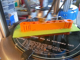
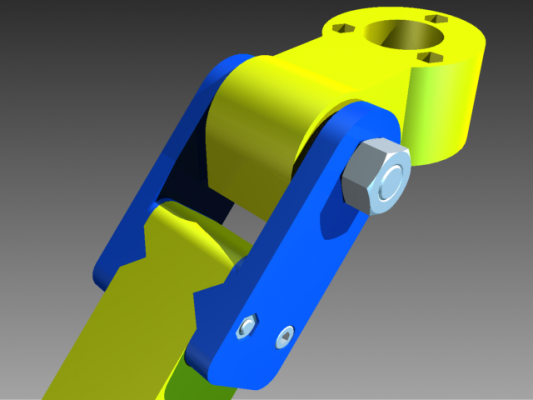
I tried to eliminate play by press fitting the aluminum tube in the shoulder and machining a land on the aluminum tube for the bearing inner race to rest against. The installation is simple, I slightly pried open the fork and pushed it over the aluminum tube until they snapped into place.
The design of the arm is not for structure, it's mostly for cool factor, it actually weighs a little bit over the square arm but maybe that's because my Square arm has low fill percentage.
bolt = 53 g aluminum tube and bearings 11g
Here's a picture of the printer in progress, you can see it needs quite a bit of support laying down in this configuration. [www.thingiverse.com]
@ A2
I initially tried 2 approaches, one with steps on the aluminum tube and one without. I think it's necessary to have the steps to eliminate any side play with this configuration.
You have a lot of good suggestions and I'm sure we can all refine this attachment. And yes I did drill out the aluminum slug today which resulted in substantial weight savings.
Edited 1 time(s). Last edit at 02/19/2014 08:37PM by Dannydefe.
I tried to eliminate play by press fitting the aluminum tube in the shoulder and machining a land on the aluminum tube for the bearing inner race to rest against. The installation is simple, I slightly pried open the fork and pushed it over the aluminum tube until they snapped into place.
The design of the arm is not for structure, it's mostly for cool factor, it actually weighs a little bit over the square arm but maybe that's because my Square arm has low fill percentage.
bolt = 53 g aluminum tube and bearings 11g


Here's a picture of the printer in progress, you can see it needs quite a bit of support laying down in this configuration. [www.thingiverse.com]
@ A2
I initially tried 2 approaches, one with steps on the aluminum tube and one without. I think it's necessary to have the steps to eliminate any side play with this configuration.
You have a lot of good suggestions and I'm sure we can all refine this attachment. And yes I did drill out the aluminum slug today which resulted in substantial weight savings.
Edited 1 time(s). Last edit at 02/19/2014 08:37PM by Dannydefe.
|
Re: LISA Simpson February 19, 2014 08:58PM |
Registered: 10 years ago Posts: 979 |
@Dannydefe: Could we not just integrate the functionality of the aluminum slug into a printed part? My other concern is with the 6702s. They are cheap enough but 4 times the cost of a 608. That one distinction adds $10 to the BOM.
ConceptFORGE
Wally, GUS Simpson, LISA Simpson, THOR Simpson, Sextupteron, CoreXZ
ConceptFORGE
Wally, GUS Simpson, LISA Simpson, THOR Simpson, Sextupteron, CoreXZ
|
Re: LISA Simpson February 19, 2014 09:50PM |
Registered: 10 years ago Posts: 1,381 |
Another idea:
Design some thing like what Nicholas suggested, a detachable bearing pocket.
But the pockets for both sides are closed, this will trap the shaft.
To save weight, glue the bearing pocket to the arm.
@uncle_bob:
I don't think you can tension the arms between the Roton screw and hub, as the other two arms would move towards the tensioning member.
|
Re: LISA Simpson February 20, 2014 06:06PM |
Registered: 10 years ago Posts: 47 |
@ Nicholas
It's a good suggestion to try to build the entire assembly from printed components . The reason I went to the larger diameter was to get good bearing surface on the shoulder. Also my ultimate goal is not only to have a printer but to have the components strong enough to handle CNC.
It's a good suggestion to try to build the entire assembly from printed components . The reason I went to the larger diameter was to get good bearing surface on the shoulder. Also my ultimate goal is not only to have a printer but to have the components strong enough to handle CNC.
|
Re: LISA Simpson February 21, 2014 10:06PM |
Registered: 10 years ago Posts: 1,433 |
Hi
Early on thrust bearings were discussed, and rejected (I think) based on cost.
[www.vxb.com]
Do not appear to be overly expensive if you can use a bunch of them.
They do not fit nicely on an arbitrary metric bolt .....
Bob
Early on thrust bearings were discussed, and rejected (I think) based on cost.
[www.vxb.com]
Do not appear to be overly expensive if you can use a bunch of them.
They do not fit nicely on an arbitrary metric bolt .....
Bob
|
Re: LISA Simpson March 10, 2014 03:50PM |
Registered: 10 years ago Posts: 67 |
Quick question: do you print the bottom hub piece solid? I printed it 6 shells with 30%, but ended up snapping the main column off the base. It was probably my fault for not being careful enough when I was handling it, but I wanted to know what you guys have done.
"Never argue with stupid people, they will drag you down to their level and then beat you with experience."
"Never argue with stupid people, they will drag you down to their level and then beat you with experience."
|
Re: LISA Simpson March 10, 2014 03:56PM |
Registered: 10 years ago Posts: 979 |
I have snapped a couple of these. You can use the hub from GUS after you mirror them or the shoulder mounts. The screw is removable for GUS. (Sorry for not keeping the same chirality as GUS.)
Edited 1 time(s). Last edit at 03/10/2014 03:58PM by nicholas.seward.
ConceptFORGE
Wally, GUS Simpson, LISA Simpson, THOR Simpson, Sextupteron, CoreXZ
Edited 1 time(s). Last edit at 03/10/2014 03:58PM by nicholas.seward.
ConceptFORGE
Wally, GUS Simpson, LISA Simpson, THOR Simpson, Sextupteron, CoreXZ
|
Re: LISA Simpson March 11, 2014 01:33AM |
Registered: 10 years ago Posts: 1 |
Insomniac inquiry:
Given that the vertical elements of the Lisa are subject to torsion (I saw beams for triangulation early on), would a cylindrical sheet of thin material anchored to circular cap and foot plates help resist that motion?
A low elasticity plastic sheet would be inexpensive and assist in temperature control maybe?
http://www.tapplastics.com/product/plastics/plastic_sheets_rolls/ldpe_sheets/410
Unsure. Love this design. Also, hi all.
-|\/|/
|
Re: LISA Simpson March 11, 2014 01:24PM |
Registered: 10 years ago Posts: 2 |
1. Counter-bore the threaded rods and mount them directly to stepper shafts, press bearings into the top and bottom plates and screw the steppers directly to the bottom plate and you can delete all other rod support parts.
2. Put slots in the top and bottom panels for vertical sheet metal, acrylic, fiberglass or plywood panels. It would be rock solid if you made one formed sheet metal or acrylic panel that wrapped like the attached file...
3. Make rubber feet to slip on the motor bottoms to make the motors the support feet for the system.
|
Re: LISA Simpson March 11, 2014 04:37PM |
Registered: 10 years ago Posts: 979 |
@Tshulthise
1) I don't have a lathe so that is a problem but would be a good option if you had one. If I did that, you just get rid of the coupler. You still need two bearings and two thread clamps per screw.
2) Would be great.
3) Not a bad option but I opted for one more plate to give me a good place to put electronics.
ConceptFORGE
Wally, GUS Simpson, LISA Simpson, THOR Simpson, Sextupteron, CoreXZ
|
Re: LISA Simpson March 17, 2014 09:26PM |
Registered: 10 years ago Posts: 47 |
Here's photos of my most recent progress. I posted a couple of other photos too.
[forum.conceptforge.org]
The inline arm with the large aluminum pins seems to have very little play, I'm quite pleased with this configuration.
[forum.conceptforge.org]
The inline arm with the large aluminum pins seems to have very little play, I'm quite pleased with this configuration.


|
Re: LISA Simpson March 18, 2014 03:50AM |
Registered: 10 years ago Posts: 1,381 |

|
Re: LISA Simpson March 18, 2014 08:37PM |
Registered: 10 years ago Posts: 47 |
|
Re: LISA Simpson May 27, 2014 09:07AM |
Registered: 9 years ago Posts: 210 |
Really interesting read and I love the design of LISA! I've posted a couple of questions in the concept forge forum but I mostly could answer them myself after reading this whole thread.
But I was wondering if anyone had any thoughts or ideas for a Kossel style effector mount to be able to change tools or have bigger extruders like a dual / quad extruder (e.g. the kraken)? I guess the simple solution would be to have bottom mounted tools and sacrifice a bit of build height?
Also, the interest in the design seemd to have ebbed down a bit, is this because of all the focus on wally or because of the problems with sourcing lead screws / limited effector mount space?
My other idea while reading all this was to use a position tracking system instead of precise lead screws and stepper motors. You could use a rather cheap raspberry PI with a camera cape. You might be able to do up to 90 FPS of position tracking some IR/colored LEDs. 3 mounted on the bed in an equilateral triangle, 2 mounted left and right of the extruder. That way you could adjust speed and positioning and auto calibrate (you could calculate the plane of the hot bed and see when the extruder stops).
This might enable you to use cheap threadless ball screws, not need expensive lead screws or nuts. It would also allow to compensate for any build inaccuracies. Ideal would be to use either a beaglebone black or a raspberry pie with a camera (usb or cape) and directly controlling the stepper motors.
Edited 3 time(s). Last edit at 05/27/2014 09:09AM by Dejay.
|
Re: LISA Simpson May 27, 2014 12:27PM |
Registered: 11 years ago Posts: 1,049 |
Dejay
Interesting system
Do you have hardware and code for your measurement system?
Is there a URL?
I have been working on threadless leadscrews
and they are not very accurate/repeatable
[forums.reprap.org]
No one in the 3D printing world uses positioning by measurement feedback.

Interesting system
Do you have hardware and code for your measurement system?
Is there a URL?
I have been working on threadless leadscrews
and they are not very accurate/repeatable
[forums.reprap.org]
No one in the 3D printing world uses positioning by measurement feedback.
|
Re: LISA Simpson May 27, 2014 12:56PM |
Registered: 10 years ago Posts: 979 |
@Dejay: This design was mostly just a proof of concept. I tried to envision a column delta that could take advantage of lead screws. I think this is a pretty good stab at that but it doesn't remove some of the problems LISA will always have. If you are using a lead screw or a threadless rod, you are bound to have some wobble and that will manifest itself in the print. For LISA-0 it wasn't enough of a problem that I couldn't get her to self replicate. I have used LISA to print many parts for my other printers. However, even being the creator, I find it hard to recommend her over most other designs. The reason to like her is that she is unusual and different. I would like people to occasionally break with conventional thinking and see if we can get some lateral movement in the RepRap community. I am all for forward movement but sometimes you need to go sideways or backward before you can go forward again.
Multiple Extruder Concept: You could use this idea on a LISA. It just breaks the symmetry and makes the math worse. Nothing we can't handle but it will make calibration that much harder and that is before we consider the calibration needed for the nozzle offsets.
Have you done the math on what precision you can find your position with a webcam? My calculations tell me that I can get all the precision that I need in 1 direction (z in this case) but the x and the y resolution is pretty poor. (I guess one solution is to use 3 webcams with 3 reference led planes.) I agree with cozmicray that no printers do anything like this but to me that is a huge invitation to be the first. I "know" this is where we are going. Think about it. All the components you talked about are cheap and getting cheaper. The advantages are huge. The problem is that there is no firmware/software on the shelf.
Happy hacking!
ConceptFORGE
Wally, GUS Simpson, LISA Simpson, THOR Simpson, Sextupteron, CoreXZ
|
Re: LISA Simpson May 27, 2014 11:39PM |
Registered: 9 years ago Posts: 210 |
@Cozmicray
It's not really my system or anything, it's just an idea so far. I'm really just a loudmouth But there is a free software called "FaceTrackNoIR" that ironically tracks IR diodes on your head using simple point tracking (used to control the view direction of players in video games).
@Nicholas
You certainly brought some lateral thinking into reprap! I love your designs! I can't wait for your next design
Thanks for linking that video, that's awesome. I wasn't sure if a center hub like that would stay level, but seeing the video I guess it would have to, just like in a Rostock. For LISA, a bigger central hub would cost a bit of print diameter, but I think it's important to see that it's possible to extend.
About the tracking, I think the theoretical precision is rather high. If you would track an led that shows a "drop off" in the camera image, you can use the intensity gradient to improve precision. If you'd place the camera so that the field of view frustum encloses the print area tightly, you'd have an ideal angular resolution of webcam resolution * color channel depth. For a raspberry camera that might be 640*64 so the theoretical X/Y precision should be something like 200mm / (640*64) = 0.0048 mm an the center plane of the print area (XY in screen coordinates). Z resolution would be much worse and depends of the field of view.
Also the bigger the blob you are tracking the more precision you get. I guess either the radius or the area of the blob in pixel you are tracking could theoretically scale up the precision.
So high resolution is actually not that important for tracking a smooth blob, since it would reduce the radius of the blob in pixels. Practically the camera noise and lens distortion would reduce this theoretical resolution quite a bit. Not sure if it's better to track small white balls illuminated by IR light, or something like green LEDs inside a spherical translucent ball (greenscreen segmentation, less IR reflectance, but less "intensity fall off").
The Raspberry PI would probably be ideal for this since afaik the camera pictures are transferred and processed directly on it's (tiny) GPU. So you could run a OpenGL ES shader to track those blobs or at least preprocess them so that the cpu doesn't have that much to do. Unfortunately I didn't find any stepper motor control boards for the Raspberry like for the Beaglebone black.
I'm not sure if the Beaglebone Black has enough power to do this on the CPU. But a high frame rate might not be that important to calibrate and fix positioning errors. I'll try capturing some images on my BBB with the PS3 eye but I'm a noob at linux and also pretty lazy, so I don't promise anything!
I'm just thinking aloud with all this, but I think a true self replicating printer could benefit greatly because you can relax many of the precision engineering constraints. This might allow you to use less print quality, cheaper motors (maybe no stepper motors at all), compensate for things like backlash or arm droop. The human arm isn't a precision machine at all, but if we look at what we are doing, we can be very precise. A firmware that compensates for that in real time will need the horse power of an ARM CPU though.
Edited 1 time(s). Last edit at 05/27/2014 11:40PM by Dejay.
It's not really my system or anything, it's just an idea so far. I'm really just a loudmouth
But there is a free software called "FaceTrackNoIR" that ironically tracks IR diodes on your head using simple point tracking (used to control the view direction of players in video games). @Nicholas
You certainly brought some lateral thinking into reprap! I love your designs! I can't wait for your next design
Thanks for linking that video, that's awesome. I wasn't sure if a center hub like that would stay level, but seeing the video I guess it would have to, just like in a Rostock. For LISA, a bigger central hub would cost a bit of print diameter, but I think it's important to see that it's possible to extend.
About the tracking, I think the theoretical precision is rather high. If you would track an led that shows a "drop off" in the camera image, you can use the intensity gradient to improve precision. If you'd place the camera so that the field of view frustum encloses the print area tightly, you'd have an ideal angular resolution of webcam resolution * color channel depth. For a raspberry camera that might be 640*64 so the theoretical X/Y precision should be something like 200mm / (640*64) = 0.0048 mm an the center plane of the print area (XY in screen coordinates). Z resolution would be much worse and depends of the field of view.
Also the bigger the blob you are tracking the more precision you get. I guess either the radius or the area of the blob in pixel you are tracking could theoretically scale up the precision.
So high resolution is actually not that important for tracking a smooth blob, since it would reduce the radius of the blob in pixels. Practically the camera noise and lens distortion would reduce this theoretical resolution quite a bit. Not sure if it's better to track small white balls illuminated by IR light, or something like green LEDs inside a spherical translucent ball (greenscreen segmentation, less IR reflectance, but less "intensity fall off").
The Raspberry PI would probably be ideal for this since afaik the camera pictures are transferred and processed directly on it's (tiny) GPU. So you could run a OpenGL ES shader to track those blobs or at least preprocess them so that the cpu doesn't have that much to do. Unfortunately I didn't find any stepper motor control boards for the Raspberry like for the Beaglebone black.
I'm not sure if the Beaglebone Black has enough power to do this on the CPU. But a high frame rate might not be that important to calibrate and fix positioning errors. I'll try capturing some images on my BBB with the PS3 eye but I'm a noob at linux and also pretty lazy, so I don't promise anything!
I'm just thinking aloud with all this, but I think a true self replicating printer could benefit greatly because you can relax many of the precision engineering constraints. This might allow you to use less print quality, cheaper motors (maybe no stepper motors at all), compensate for things like backlash or arm droop. The human arm isn't a precision machine at all, but if we look at what we are doing, we can be very precise. A firmware that compensates for that in real time will need the horse power of an ARM CPU though.
Edited 1 time(s). Last edit at 05/27/2014 11:40PM by Dejay.
|
Re: LISA Simpson June 24, 2014 07:10AM |
Registered: 9 years ago Posts: 210 |
I've found some rather cheap ball screws on ebay 800mm and 1610 (apparently 10 mm lead), in the range of $60 with free shipping. These have less lead than the high lead screws, but they also have far less friction. Would this work / compensate so that you could use higher RPM on the motor instead of higher lead?
|
Re: LISA Simpson June 24, 2014 09:58AM |
Registered: 10 years ago Posts: 979 |
So $180 for a set of 3. I think these would be perfect. They should be super straight and there should be no backlash.
I think you would be happy with the speed reduction. I never really hit the ceiling during a print on LISA.
ConceptFORGE
Wally, GUS Simpson, LISA Simpson, THOR Simpson, Sextupteron, CoreXZ
I think you would be happy with the speed reduction. I never really hit the ceiling during a print on LISA.
ConceptFORGE
Wally, GUS Simpson, LISA Simpson, THOR Simpson, Sextupteron, CoreXZ
|
Re: LISA Simpson July 12, 2014 04:18AM |
Registered: 10 years ago Posts: 2 |
To my understanding, only one type of extruder fits on this printer due to the center pivot. Someone could maybe look into a center plate with virtual pivot point hinges. In this way, a clean platform is available and the arm connections are more symetric. Moreover, fans and lights can be placed which is not easely possible at this moment. Here is a picture of my idea
. The blue block is a third of the extruder platform. At the moment the lisa extruder platform has a real pivot point going through the tip of the extruder. One could create a virtual pivot point around the same extruder tip, But place the hinge further to the side. By using the virtual pivot point, one gains a clean extruder platform. However, three additional linkages will be needed and I have no idea if this complicates calibration of the printera lot.

|
Re: LISA Simpson July 12, 2014 10:17AM |
Registered: 10 years ago Posts: 67 |
Quote
paddy92
To my understanding, only one type of extruder fits on this printer due to the center pivot. Someone could maybe look into a center plate with virtual pivot point hinges. In this way, a clean platform is available and the arm connections are more symetric. Moreover, fans and lights can be placed which is not easely possible at this moment. Here is a picture of my idea [attachment 36376 Real-and-virtual-pivot-point.png] . The blue block is a third of the extruder platform. At the moment the lisa extruder platform has a real pivot point going through the tip of the extruder. One could create a virtual pivot point around the same extruder tip, But place the hinge further to the side. By using the virtual pivot point, one gains a clean extruder platform. However, three additional linkages will be needed and I have no idea if this complicates calibration of the printera lot.
I am lost. What is the problem you are trying to solve here? I do not get a clear explanation of why you want to modify the design this way (whats the take-away) and further, I do not get how you need to add more linkages to offset the extruder. Actually, I am lost as to what you call an extruder. Do you mean the hotend, or the extrusion motor, or putting both together on the moving carriage?
"Never argue with stupid people, they will drag you down to their level and then beat you with experience."
|
Re: LISA Simpson July 12, 2014 11:50AM |
Registered: 9 years ago Posts: 210 |
Paddy that's a really interesting idea! I have no clue how a virtual pivot would work and how to realize it though.
@Hazer AFAIK extruder meant originally both the hotend (which extrudes the plastic) and the extruder motor. But yes paddy means the hotend.
The "problem" with the lisa effector platform (where the hotend is) is that the kinematics work in a way that the arms are attached and rotate around the center axis of the effector platform, only leaving a 2mm tube for the filament.
Probably the multi extruder proof of concept nicholas made is the better solution, even though it requires a more complex software kinematics and a faster controller. But the easier and the less joints the higher the precision.
|
Re: LISA Simpson July 12, 2014 12:00PM |
Registered: 10 years ago Posts: 979 |
@paddy92: The math doesn't work out if you connect to a plate instead of a point. I really wanted to do it that way on both LISA and GUS but math wouldn't cooperate. This is the current best way I know how to do what you want but it destroys the symmetry and makes the kinematics nasty as a result.
Actually, here is a way to do what you want without destroying the math. For LISA, you have to have another screw and another arm on one side. Technically you could do this for GUS with two arms on one side. (Thanks for posting. I never would have realized I could use this double up method for GUS without you making me think about this again.)
ConceptFORGE
Wally, GUS Simpson, LISA Simpson, THOR Simpson, Sextupteron, CoreXZ
|
Re: LISA Simpson July 12, 2014 12:36PM |
Registered: 9 years ago Posts: 210 |
|
Re: LISA Simpson July 12, 2014 12:55PM |
Registered: 10 years ago Posts: 979 |
@Dejay: I really like that solution also. In fact, I am going to order some balls and try this out just to see what I think. However, there are a few consequences. If the hub offset is different from the shoulder offset the math goes over the AVR ledge. It would be simple for an ARM. The math also still gets harder if the effector isn't centered because every arm has to rotate relative to the base.
ConceptFORGE
Wally, GUS Simpson, LISA Simpson, THOR Simpson, Sextupteron, CoreXZ
ConceptFORGE
Wally, GUS Simpson, LISA Simpson, THOR Simpson, Sextupteron, CoreXZ
|
Re: LISA Simpson July 16, 2014 02:54PM |
Registered: 9 years ago Posts: 135 |
|
Re: LISA Simpson July 16, 2014 04:56PM |
Registered: 11 years ago Posts: 1,049 |
|
Re: LISA Simpson July 16, 2014 05:02PM |
Registered: 11 years ago Posts: 1,049 |
Dejay
did you get some of these ball screws?
How are they?
With 800mm length --- what would be the print volume dimensions?
Tnx

did you get some of these ball screws?
How are they?
With 800mm length --- what would be the print volume dimensions?
Tnx
Quote
Dejay
I've found some rather cheap ball screws on ebay 800mm and 1610 (apparently 10 mm lead), in the range of $60 with free shipping. These have less lead than the high lead screws, but they also have far less friction. Would this work / compensate so that you could use higher RPM on the motor instead of higher lead?
|
Re: LISA Simpson July 16, 2014 05:05PM |
Registered: 11 years ago Posts: 1,049 |


Sorry, only registered users may post in this forum.