LISA Simpson
Posted by nicholas.seward
|
Re: LISA Simpson November 24, 2013 09:57PM |
Registered: 10 years ago Posts: 1,433 |
Six feet of 6063 aluminum tube 2" in diameter is still under $20. I suspect it's a bit more sturdy than the PVC.
[www.onlinemetals.com]
Edited 1 time(s). Last edit at 11/24/2013 09:58PM by uncle_bob.
[www.onlinemetals.com]
Edited 1 time(s). Last edit at 11/24/2013 09:58PM by uncle_bob.
|
Re: LISA Simpson November 26, 2013 11:10AM |
Registered: 11 years ago Posts: 979 |
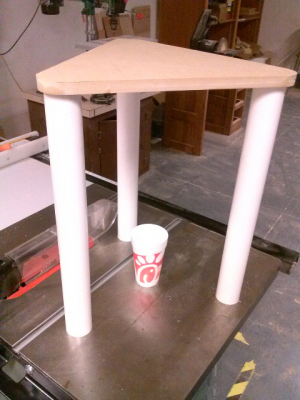
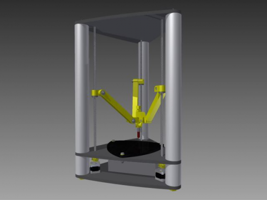
Here is a mockup of the scale of LISA. It is bigger than I thought but not so big it can't fit on a desktop. I know a lot of people don't like the PVC but after hammering the PVC into the milled sockets for just one board I get a structure that is good enough for slow printing. Once I get the bottom plate it will probably be good enough for normal printing. With the tension from the screws it will be prefect for fast printing.
The main reason I am using PVC is that it is simple and I have a lot of it laying around. (FREE!) It will be great for this prototype. For those that want to conserve desk space, I would suggest going with a design like Dannydefe's. You could fit everything into a 16" diameter circle easy. Currently, the PVC makes the foot print 21" in diameter.
|
Re: LISA Simpson November 27, 2013 07:14PM |
Registered: 10 years ago Posts: 47 |
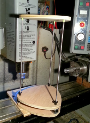
Here's the progress I made today, just doing first mock up to see how it looks.
Tomorrow I will start on the side structure and stepper motor placement.
Is there any opinion on how much Z this machine should have ?
Tomorrow I will start on the side structure and stepper motor placement.
Is there any opinion on how much Z this machine should have ?
|
Re: LISA Simpson November 27, 2013 08:00PM |
Registered: 11 years ago Posts: 979 |
@Dannydefe: I am going to make it as tall as possible. You will need about 1" on each side for the thread clamp and the coupler. I am going to have the coupler double as the bottom thread clamp. Looks awesome BTW.
I got my screws and nuts today and any worries I had about friction, backlash, straightness, etc have gone away. They will be perfect in my opinion.
I am going to add a bottom plate like you have. I will mill sockets for the steppers. I will remove two of the back screws of the stepper and replace them with longer ones so I can bolt throught the bottom board.
Additionally, I am going to get some cheap threaded rod to go through the middle of the PVC columns to make assembly super easy and make everythong very rigid.
|
Re: LISA Simpson November 27, 2013 10:00PM |
Registered: 10 years ago Posts: 1,433 |
|
Re: LISA Simpson November 29, 2013 10:37AM |
Registered: 10 years ago Posts: 17 |
|
Re: LISA Simpson November 30, 2013 09:37AM |
Registered: 10 years ago Posts: 1,433 |
Two sides + door + fan + heater for temperature control would be pretty neat. You could keep the PVC pipe or go to CPVC for higher temps ...
-----------------
If the steppers are buried in the support structure *and* really go for max torque / speed - they will get pretty hot. This may be a high torque design. You might consider allowing for fan mounts near each motor.
-----------------
If the steppers are buried in the support structure *and* really go for max torque / speed - they will get pretty hot. This may be a high torque design. You might consider allowing for fan mounts near each motor.
|
Re: LISA Simpson December 01, 2013 08:02PM |
Registered: 12 years ago Posts: 85 |
|
Re: LISA Simpson December 01, 2013 09:27PM |
Registered: 10 years ago Posts: 17 |
Quote
uncle_bob
Six feet of 6063 aluminum tube 2" in diameter is still under $20. I suspect it's a bit more sturdy than the PVC.
[www.onlinemetals.com]
Yes, I think I agree about the sturdiness. I think PVC tends to deform slowly.
David
|
Re: LISA Simpson December 02, 2013 12:05PM |
Registered: 10 years ago Posts: 20 |
I imagine this design, coupled with the "threadless ballscrew" could be great (e.g, [www.thingiverse.com], I just pulled the first one I found its not the best.) Way to take what first sounds like a bad idea (threadscrews) and turning into a feasible lowcost design. Props!
|
Re: LISA Simpson December 02, 2013 12:58PM |
Registered: 11 years ago Posts: 979 |
|
Re: LISA Simpson December 02, 2013 02:06PM |
Registered: 10 years ago Posts: 1,381 |
|
Re: LISA Simpson December 02, 2013 02:08PM |
Registered: 11 years ago Posts: 979 |
|
Re: LISA Simpson December 02, 2013 02:24PM |
Registered: 10 years ago Posts: 1,381 |
It's too many years since I've seen one, I don't know how far off it could be after 1000's of moves, another engineers project.
But they are good for slightly dirty wet environment.
Creep of the plastic housing, and the shaft that holds the bearing would be my main concern for a DIY version.
I've only seen aluminum block used with precision threaded shaft, I forget the name, Carr Lane or another supplier used to have a precision shaft SHCS.
I can't locate it found this: [www.carrlane.com]
Found it: precision shoulder screws
[www.mcmaster.com]
Edited 1 time(s). Last edit at 12/02/2013 02:26PM by A2.
|
Re: LISA Simpson December 03, 2013 12:59PM |
Registered: 10 years ago Posts: 20 |
|
Re: LISA Simpson December 03, 2013 01:08PM |
Registered: 11 years ago Posts: 979 |
|
Re: LISA Simpson December 03, 2013 02:30PM |
Registered: 11 years ago Posts: 102 |
Would a spinning threadless ballscrew work as a filament driver? Or is the diameter of filament too unreliable? The biggest hurtle I can think of is that variation in the filament diameter would cause the ballscrew to disengage.
Edited 1 time(s). Last edit at 12/03/2013 02:49PM by PeteD.
Edited 1 time(s). Last edit at 12/03/2013 02:49PM by PeteD.
|
Re: LISA Simpson December 03, 2013 08:04PM |
Registered: 10 years ago Posts: 47 |
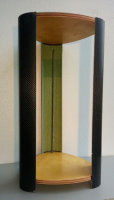
This is just a preliminary set up to see how it looks. The corner caps were made off a temporary mold and the carbon /Fiberglass was resin infused. I've extended the carbon corners down to cover the stepper installation.
Comments Welcome..
Comments Welcome..
|
Re: LISA Simpson December 03, 2013 08:10PM |
Registered: 10 years ago Posts: 47 |
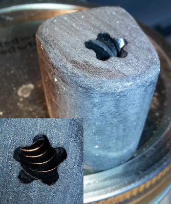
Here's a photo of my attempt to make a nut from the Torqspline® Screws. I used epoxy and graphite . first waxed and then a couple of coats of spray PVA for release agent. Although the threads turned out perfect, the friction is just much too high. I guess someone could try and use a different type of coating over the threads to build them up but I think I'll just buy the nuts for now.
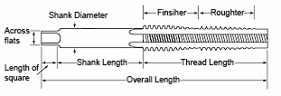
Another alternative if several of us would like to pitch in, is the purchase of a tap (www.roton.com/page.aspx?id=41) for this particular screw. The tap is quite expensive but maybe if we were going to build several machines it would be worth the cost.
Another alternative if several of us would like to pitch in, is the purchase of a tap (www.roton.com/page.aspx?id=41) for this particular screw. The tap is quite expensive but maybe if we were going to build several machines it would be worth the cost.
|
Re: LISA Simpson December 03, 2013 08:20PM |
Registered: 11 years ago Posts: 979 |
|
Re: LISA Simpson December 03, 2013 09:12PM |
Registered: 10 years ago Posts: 47 |
I seriously doubt if these can be manufactured on a lathe without extreme experience. let's produce the first couple of prototypes and if all goes well we can purchase the tap and make a bunch of nuts.
|
Re: LISA Simpson December 03, 2013 10:27PM |
Registered: 10 years ago Posts: 1,381 |
@Dannydefe
A few ideas:
Graphite loading:
If there is not a heavy loading of graphite at the interface of the nut and thread, it will always be sticky, and require lubrication.
Purchased Tap:
Keep in mind that the tap will in general reproduce the same size of the nut that you purchased.
If you were for an example to use Nylon rod and tap it, most likely it will be undersized, and produce a tight fit.
To compensate for this you will need to increase the hole diameter.
Trade off is you have less surface area in contact.
Thermoforming:
You might be able to heat up the threaded rod and thermoform a plastic nut.
Chrome plate threaded rod:
Another technique is to build up the surface of the threaded rod by chrome plating it.
Then cast your epoxy/graphite over it.
Adjustable nut:
Split the nut with a Dremel cutoff wheel.
Use a metal hose clamp to adjust the fit up between the shaft and epoxy/graphite nut.
Or, in addition to the split nut, cross drill in the region without threads and use a bolt and nut to clamp/adjust tension.
Lapping:
Use a lapping compound and run the shaft back and forth through the nut until if feels right to you.
Homemade tap:
You can make a tap from the threaded rod by grinding out flutes, I've done this many time to clean out damaged threads.
Cut the flutes at an angle so it can shear.
As it becomes dull regrind the flutes.
If you are cutting a hard material, a negative rake might product better result.
Case hardening:
If the threaded shaft is too soft to work as a tap you can case harden it, lots of ways to approach this, here's an old fashion technique.
Wrap a section of the shaft in leather, place it in a crucible (or wrap in SS foil) and heat it.
Time and temperature can be found with a search.
|
Re: LISA Simpson December 03, 2013 10:29PM |
Registered: 11 years ago Posts: 979 |
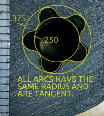
This is my best stab at reverse engineering the tooth form. After several requests for the engineering drawings, ROTON final told me it was a trade secret. I have no problem with that but a simple no would have been sufficient. I had to write 3 emails to get to that point. One interesting note did come about. They were willing to give me quotes for shaft couplers and thread clamps if I would have provided them with drawings of the blanks. Anyways, I am off to do some printed thread clamp tests.
|
Re: LISA Simpson December 03, 2013 10:43PM |
Registered: 10 years ago Posts: 1,381 |
Quote
PeteD
Would a spinning threadless ballscrew work as a filament driver? Or is the diameter of filament too unreliable?
The biggest hurtle I can think of is that variation in the filament diameter would cause the ballscrew to disengage.
I had the same idea, and have made paper sketch of it as a reminder.
The main challenge that I see with it is that the filament would rotate with a single drive.
Another problem is when you reversed the drive to retract the filament, the unwinding would work against you.
Couple of ways to work around this:
It would require two sets that counter rotate with opposing complementary helix angles.
Counter rotating would prevent the filament from twisting.
This would require a belt to drive them.
The drive mechanics is not simple, and the support would be rather large.
To eliminate two counter rotating drives, a knife edge roller could be used to prevent rotation of the filament.
The sharp edge would bite into the filament forming a grove to prevent the filament from rotating.
This would be the easiest to implement.
To compensate for variable filament diameter, spring tension could be used.
But you never know, the amount of compression to drive the filament might be enough to compensate for a variable diameter.
|
Re: LISA Simpson December 03, 2013 11:11PM |
Registered: 11 years ago Posts: 979 |
Regarding filament drive:
*For 1.75mm filament you need 604s or smaller.
*Counter rotating could be done with bevel gears.
*You could use the edge of the bearing instead of the flat to increase the grip and remove almost all of the sliding friction.
I really like this idea. I think I can do it with 6 604s and 3 608s and some random bolts. It has enough potential to warrant a mock up and a possible test. I will put it in the developer forum when I get the time.
|
Re: LISA Simpson December 04, 2013 05:40AM |
Registered: 11 years ago Posts: 979 |
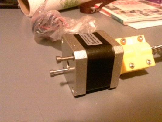
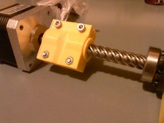
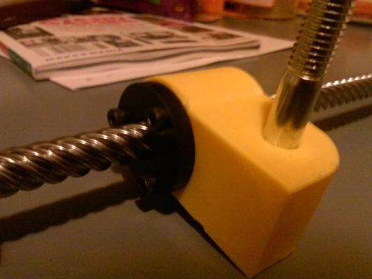
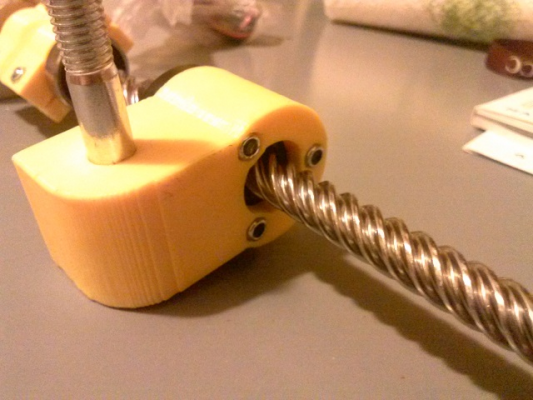
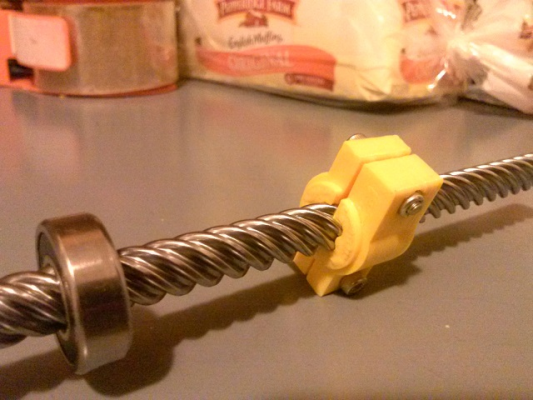
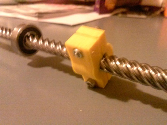
Mounting Screws/Stepper
Coupler
Carriage
Thread Clamp
I have to say that everything is coming together beautifully. This design has some promise.
|
Re: LISA Simpson December 04, 2013 07:54AM |
Registered: 11 years ago Posts: 979 |
|
Re: LISA Simpson December 04, 2013 08:02AM |
Registered: 10 years ago Posts: 1,381 |
The metal screws make this concept a better platform for the globular deposition modeling of metal welding (GDMm), as it could support a lot of weight!
Add a worm drive, and it could really lift/support a heavy weight.
Components are looking good!
What is the fit of the bearing like over the threads (slip, interference)?
Edited 1 time(s). Last edit at 12/04/2013 08:05AM by A2.
Add a worm drive, and it could really lift/support a heavy weight.
Components are looking good!
What is the fit of the bearing like over the threads (slip, interference)?
Edited 1 time(s). Last edit at 12/04/2013 08:05AM by A2.
|
Re: LISA Simpson December 04, 2013 08:08AM |
Registered: 11 years ago Posts: 979 |
|
Re: LISA Simpson December 04, 2013 01:11PM |
Registered: 10 years ago Posts: 1,433 |
Sorry, only registered users may post in this forum.
