Offsets in configuration (again) 
Posted by wretan
|
Offsets in configuration (again) January 06, 2014 06:34PM |
Registered: 16 years ago Posts: 16 |
Hi everyone!
To start with, what a great forum! Tons of interesting reading before I´m starting up my own printer!
I want to build a delta but a little modification from the kossel mini as an extra challenge
My goal is making the (heated) build plate approx 300mm in diameter and total height of 700-800mm (haven´t really decided yet).
Will also try to use slotted rectangular steel tubes (C-profile) as ABC-towers and let the carriage and belt be inside the tower for a clean look. This means that I will only use some parts from the original kossel mini design. I will see how this turns out, I´m still on the CAD...
But some questions comes to my mind.
I would really appreciate if anyone will take the time to answer some of my "newbe" questions!
With best regards
Wretan
Edited 3 time(s). Last edit at 01/06/2014 06:57PM by wretan.
To start with, what a great forum! Tons of interesting reading before I´m starting up my own printer!
I want to build a delta but a little modification from the kossel mini as an extra challenge
My goal is making the (heated) build plate approx 300mm in diameter and total height of 700-800mm (haven´t really decided yet).
Will also try to use slotted rectangular steel tubes (C-profile) as ABC-towers and let the carriage and belt be inside the tower for a clean look. This means that I will only use some parts from the original kossel mini design. I will see how this turns out, I´m still on the CAD...
But some questions comes to my mind.
- I have looked a little bit on the Marlin firmware and what difference does the Delta_smooth_rod_offset and the Delta_carriage_offset do? Especially when I make a new linear bearing design... Isn´t the three other offsets (Delta_diagonal_rod, Delta_effector_offset and Delta_radius) relative the centerline the only important measures?
- And the last configuration about "Effective X/Y positions of the three vertical towers"? What should I use here? As I will CAD my frame I could of course use the theoretical distance/angle. But on the Marlins original setting the first row says: #define SIN_60 0.8660254037844386. What is this, and other values of positions, calculated from?
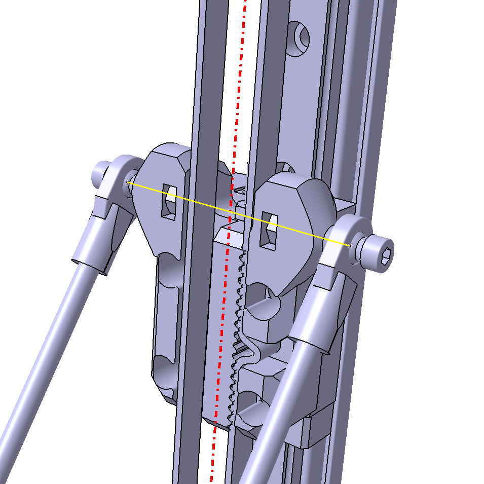
OR does the second question answer my first? I have attached a picture and Isn´t the position of the red line there relative to the centerline of the machine the most interesting? - Does the distance between the ball heads between two rods (yellow line in attached picture) make any difference? I suppose that it doesnt as long as they are the same both on the carriage and printer head
- I have checked the kossel frame calculator to get a rough length of the diagonal rods for my build but why should the rod lenght always x 0.8 of the horisontal openbeam? I suppose that longer rods also will work for example 0.9 or 1?
- And one final question. As a beginner I have hard finding a complete guide how to build a kossel mini, especially the electronic and firmware. (I have no experience of using arduino before this project).
Do you know any good (really good) tutorial for a complete build? I have seen a little bit there and a little bit here but I can´t recall that I have seen anything complete.
I would really appreciate if anyone will take the time to answer some of my "newbe" questions!
With best regards
Wretan
Edited 3 time(s). Last edit at 01/06/2014 06:57PM by wretan.
|
Re: Offsets in configuration (again) January 07, 2014 06:59AM |
Registered: 10 years ago Posts: 1,433 |
|
Re: Offsets in configuration (again) January 07, 2014 09:27AM |
Registered: 10 years ago Posts: 732 |
The bigger the horizontal size of a printed part the bigger problem with warping especialy with ABS.Quote
wretan
My goal is making the (heated) build plate approx 300mm in diameter and total height of 700-800mm (haven´t really decided yet).
At the end, the only important thing is delta_radius and it is computed like this:Quote
wretan
I have looked a little bit on the Marlin firmware and what difference does the Delta_smooth_rod_offset and the Delta_carriage_offset do? Especially when I make a new linear bearing design... Isn´t the three other offsets (Delta_diagonal_rod, Delta_effector_offset and Delta_radius) relative the centerline the only important measures?
#define DELTA_RADIUS (DELTA_SMOOTH_ROD_OFFSET-DELTA_EFFECTOR_OFFSET-DELTA_CARRIAGE_OFFSET)If you would define delta_radius manually to a number then you can ignore the offsets used for its computation.
They are measured from center of ball links, rods, platform. See e.g. this: [trains.socha.com]
Effective tower positions are only for math model to compute delta coordinates from cartesian ones. Tower positions are calculated from DELTA_RADIUS.Quote
wretan
And the last configuration about "Effective X/Y positions of the three vertical towers"? What should I use here? As I will CAD my frame I could of course use the theoretical distance/angle. But on the Marlins original setting the first row says: #define SIN_60 0.8660254037844386. What is this, and other values of positions, calculated from?
I hope you are joking with the question about SIN_60 meaning? Of course it represents value for sin(60). If you do now know what sin() means, maybe you should find somebody who will do the firmware setup for you.
It is. But at least in the original rostock it is harder to measure so it gets more complicated with carriage_offset and platform_offset and smooth_rod_offset.Quote
wretan
I have attached a picture and Isn´t the position of the red line there relative to the centerline of the machine the most interesting?
The distance does not really matter (though it must be the same on carriages and platform (pritner head)) but the bigger it is the less the printer is sensitive to precision of the diagonal rod length. So you want it as big as it is confortable (i.e. does not colide with anything else) and to not too ugly visually.Quote
wretan
Does the distance between the ball heads between two rods (yellow line in attached picture) make any difference? I suppose that it doesnt as long as they are the same both on the carriage and printer head
The rod length does not really matter. You can use whatever value you like if it is bigger than delta_radius and smaller than the height of your towers. A god default for diagonal rod length is just two times the DELTA_RADIUS.Quote
wretan
I have checked the kossel frame calculator to get a rough length of the diagonal rods for my build but why should the rod lenght always x 0.8 of the horisontal openbeam? I suppose that longer rods also will work for example 0.9 or 1?
|
Re: Offsets in configuration (again) January 09, 2014 07:35AM |
Registered: 16 years ago Posts: 16 |
Hello Uncle Bob and Hercek, Thank you very much for your time to answer my questions!
I´m not sure about the size, probably bigger isn´t always better but in some cases there would be nice to be able to print larger prototypes. I have access to a Makerbot and a Stratasys Uprint to manufacture my parts och Catia V5 to virtually test rod lengths and necessary tower height and so on. I really hope that this will be a nice delta printer and some fun on tha way building it.
Thanx for the link to John´s model making, that was really interesting pictures that explained a lot!
haha, sorry for my bad question about the SIN60 of course I know what value that corresponds to but I was curious about if the values should be changed if I made any other designs but I suppose that normal 120deg between towers.
I hope that my cad model can give the right measurements for the configuration in marlin firmware. I really hope that the actual geometry follows the theoretical model.
Thanx for answering all of my other questions, that was really helpful!
One last question, have anyone tested using a photoelectric proximity sensor as Z-probe? I have tested a couple of sensors at my work and they work pretty good even on transparent glass. How does the software do the reading, only at "calibration-state" or would the input from a photoelectric proximity sensor mess anything up? It will probably keep detecting distance even when printing but maybe the software doesn´t care?
Best regards
Wretan
I´m not sure about the size, probably bigger isn´t always better but in some cases there would be nice to be able to print larger prototypes. I have access to a Makerbot and a Stratasys Uprint to manufacture my parts och Catia V5 to virtually test rod lengths and necessary tower height and so on. I really hope that this will be a nice delta printer and some fun on tha way building it.
Thanx for the link to John´s model making, that was really interesting pictures that explained a lot!
haha, sorry for my bad question about the SIN60
of course I know what value that corresponds to but I was curious about if the values should be changed if I made any other designs but I suppose that normal 120deg between towers.I hope that my cad model can give the right measurements for the configuration in marlin firmware. I really hope that the actual geometry follows the theoretical model.
Thanx for answering all of my other questions, that was really helpful!
One last question, have anyone tested using a photoelectric proximity sensor as Z-probe? I have tested a couple of sensors at my work and they work pretty good even on transparent glass. How does the software do the reading, only at "calibration-state" or would the input from a photoelectric proximity sensor mess anything up? It will probably keep detecting distance even when printing but maybe the software doesn´t care?
Best regards
Wretan
|
Re: Offsets in configuration (again) January 09, 2014 07:55PM |
Registered: 10 years ago Posts: 732 |
You can use different angles between towers than 120°. I do not think it is a good idea. Forces are better distributed when the angles are 120°. With different angles, the part dimension errors and slack will have bigger impact too.Quote
wretan
haha, sorry for my bad question about the SIN60
The model is simplified version of reality. Some real world dimensions do not matter for cartesian -> delta coordinate coversion (which is the only thing firmware is doing differently for delta bots). If your printer will have some dimensions slightly wrong it can be fixed during calibration. Things which will not be easy to fix (current calibration does not support these):Quote
wretan
I hope that my cad model can give the right measurements for the configuration in marlin firmware. I really hope that the actual geometry follows the theoretical model.
* towers not parallel with each other,
* all diagonal rods do not have the same length,
* bed not perpendicular to towers (but you can easily fix this by padding bed).
There was a discussion on google groups [groups.google.com] about optical z-probe sensor. As far as I remember they did not achive good precision and repeatability. I think the z-probe sensor is taken into account only during G29 command (the autolevel command) if you have ENDSTOPS_ONLY_FOR_HOMING defined. But I'm not realy sure. In my opinion, matrix based autolevel is useless if you require precision of the printed parts. I do not use it. I used z-probe only for initial calibration and then I removed it from the printer.Quote
wretan
One last question, have anyone tested using a photoelectric proximity sensor as Z-probe? I have tested a couple of sensors at my work and they work pretty good even on transparent glass. How does the software do the reading, only at "calibration-state" or would the input from a photoelectric proximity sensor mess anything up? It will probably keep detecting distance even when printing but maybe the software doesn´t care?
Edited 1 time(s). Last edit at 01/09/2014 08:05PM by hercek.
Sorry, only registered users may post in this forum.