Automatic Tool Changer
Posted by 3DRapidClone
|
Automatic Tool Changer April 08, 2014 05:35PM |
Registered: 10 years ago Posts: 140 |
Has anyone else attempted automatic tool changing?
Here's a demo of it, [hackaday.com]
My kossel will have cross braces and I want to make use of it, by taking that idea and improving upon it. Multiple Recessed ND magnets should help its accuracy to "lock" into position on a slightly larger effector. Are there tutorials, or if anyone could lead me in the right direction to have set G-code run like in that video? Once I finally build my kossel, I want to attempt to use a logitech C920 for photogrammetry to 3D scan straight from within the delta.
|
Re: Automatic Tool Changer April 16, 2014 03:02PM |
Registered: 10 years ago Posts: 9 |
I'm attempting it now and was also inspired by the demo you linked. Dev has been slow =(
The two main issues I've seen are:
1. producing enough magnetic force to hold the hotend to the effector
2. repeatable positioning
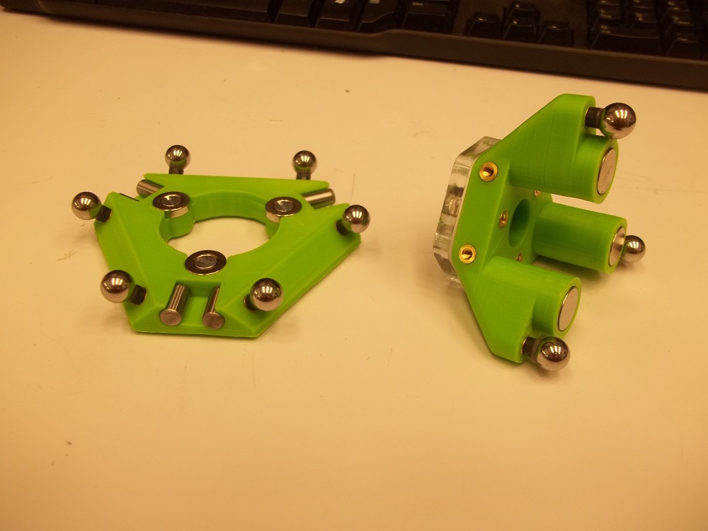
I think I've solved issue #2 w/ the pin/ball kinematic coupling setup shown in the attached pictures. The whole layout is based on the kinematic mounts sold by companies like Thorlabs for mirror positioning. I've been having problems getting the optimal magnetic force to lock the hotend and effector properly. Too low a force and the hotend will wobble and pop in/out during printing, but too high a force and it becomes very difficult to repeatably detach like in the demo video you linked. I started out with just magnetic spheres, but I had to go up to 3 pairs of magnets (6 total) in my current configuration to ensure that the hotend remains stable throughout the print. A possible future solution might the semi-permanent electromagnets (or electropermanent magnets) used in the new Google Project Ara phones, or just an electromagnet that only needs to be powered to to nullify and detach. I'm currently figuring out the placement and mounting for the hooks/braces to attach/detach the hotends.
I haven't looked into the g-code issues yet, but my original plan was to just use stock g-code that handles multiple extruders, but then manually inject in the move commands to swap out the extruders between extruder changes. Kind of lame, but I think it's a pretty straightforward solution for now.
Let me know if you have any further questions or suggestions!
The two main issues I've seen are:
1. producing enough magnetic force to hold the hotend to the effector
2. repeatable positioning
I think I've solved issue #2 w/ the pin/ball kinematic coupling setup shown in the attached pictures. The whole layout is based on the kinematic mounts sold by companies like Thorlabs for mirror positioning. I've been having problems getting the optimal magnetic force to lock the hotend and effector properly. Too low a force and the hotend will wobble and pop in/out during printing, but too high a force and it becomes very difficult to repeatably detach like in the demo video you linked. I started out with just magnetic spheres, but I had to go up to 3 pairs of magnets (6 total) in my current configuration to ensure that the hotend remains stable throughout the print. A possible future solution might the semi-permanent electromagnets (or electropermanent magnets) used in the new Google Project Ara phones, or just an electromagnet that only needs to be powered to to nullify and detach. I'm currently figuring out the placement and mounting for the hooks/braces to attach/detach the hotends.
I haven't looked into the g-code issues yet, but my original plan was to just use stock g-code that handles multiple extruders, but then manually inject in the move commands to swap out the extruders between extruder changes. Kind of lame, but I think it's a pretty straightforward solution for now.
Let me know if you have any further questions or suggestions!
|
Re: Automatic Tool Changer April 16, 2014 03:26PM |
Registered: 10 years ago Posts: 140 |
|
Re: Automatic Tool Changer April 16, 2014 03:39PM |
Registered: 10 years ago Posts: 9 |
The wobbling was in the previous iteration where the magnets from just the spheres weren't strong enough. I use ordinary ball bearings now and have the magnets separate and on the inside as shown. Recessing the pins and magnetic spheres in the original doesn't do much if your magnetic force is still too low.
Since my magnets around the hotend are towards the inside, they don't conflict w/ the magnetic arms. My biggest concern would be during detachment, but in that case, the arms should be pushing downwards on the effector, so there shouldn't be any concern for the magnetic arms to pop apart. That said, I'll probably transition to traxxas-style arms by my final iteration.
Since my magnets around the hotend are towards the inside, they don't conflict w/ the magnetic arms. My biggest concern would be during detachment, but in that case, the arms should be pushing downwards on the effector, so there shouldn't be any concern for the magnetic arms to pop apart. That said, I'll probably transition to traxxas-style arms by my final iteration.
|
Re: Automatic Tool Changer April 16, 2014 04:59PM |
Registered: 10 years ago Posts: 140 |
Whats the strength on your magnets? I am thinking about using these [www.amazon.com]
|
Re: Automatic Tool Changer April 16, 2014 05:07PM |
Registered: 10 years ago Posts: 9 |
I used these flat ones for the hotend and these countersunk ones for the bottom effector.
|
Re: Automatic Tool Changer April 21, 2014 06:32PM |
Registered: 13 years ago Posts: 485 |
|
Re: Automatic Tool Changer April 28, 2014 05:05PM |
Registered: 13 years ago Posts: 58 |
Nice work rymnd! I like the direction you have taken.
I'm going to pursue a similar construction, using 6 dowel pins and 3 ball bearings to provide a kinematic coupling. In your construction, you rely on a second set of magnets to provide the closing or clamping force. You have great control over your clamping force because you can accommodate magnets of different size. A downside is that you have added components and space claimed because you have hardware for alignment and hardware for clamping force.
I plan on integrating alignment and clamping force by using the same concept as implemented with this rack, consisting of magnets sandwiched between two ferrous plates:
[www.mcmaster.com]
(mcmaster: Screw-Mount Magnetic Tool Holder Rack)
In this case, two small disc magnets sandwiched between two locating dowel pins, oriented exactly as you have. I am waiting on hardware to show up in the mail to start playing with the magnets and to see how much clamping force is generated.
How are you holding your unused tool holders? Have you had to adjust clamping force?
Cheers!
Adam Thorp
|
Re: Automatic Tool Changer April 29, 2014 12:28AM |
Registered: 10 years ago Posts: 9 |
hey Thorp,
in my design revisions up until now, the clamping force was my biggest issue. like i mentioned above, i had started with magnetic ball bearings and also tried magnetic ball bearings w/ additional magnets situated beneath the dowel pins. my hotend tended to pop out of the coupling during prints (especially during fast moves) until i switched to using 6 total magnets in my current setup. i would love to have the positioning and clamping components together, but i was never able to get it to work. please let me know if you have better success!
in my design revisions up until now, the clamping force was my biggest issue. like i mentioned above, i had started with magnetic ball bearings and also tried magnetic ball bearings w/ additional magnets situated beneath the dowel pins. my hotend tended to pop out of the coupling during prints (especially during fast moves) until i switched to using 6 total magnets in my current setup. i would love to have the positioning and clamping components together, but i was never able to get it to work. please let me know if you have better success!
|
Re: Automatic Tool Changer May 03, 2014 12:30AM |
Registered: 13 years ago Posts: 58 |
Santa brought me something today!
Arranged based on the principle I mentioned earlier. Pairs of disc magnets oriented in the same direction to create an open circuit that the ball bearing closes.
As you might expect, the arrangements with thinner magnets are weaker and thicker magnets, stronger. I don't really know how much force will be required but I am confident I can get it with this approach. Forward I go!
Cheers,
Thorp
|
Re: Automatic Tool Changer May 03, 2014 01:37AM |
Registered: 10 years ago Posts: 9 |
Neat! Never tried arranging magnets, pins, and bearings like that before. It certainly feels different from when I tried just pins and magnetic ball bearings, but still a lot weaker than my current setup. My issue before was that the effector could pop up, lose contact with the pins, and then not pop back down afterwards. Hope you have better results!
|
Re: Automatic Tool Changer May 04, 2014 04:08PM |
Registered: 13 years ago Posts: 58 |
|
Re: Automatic Tool Changer May 15, 2014 01:45PM |
Registered: 13 years ago Posts: 58 |
|
Re: Automatic Tool Changer July 11, 2014 02:23AM |
Registered: 10 years ago Posts: 140 |
After doing some more R&D on the tool changing, perhaps there's a better way to change a toolhead than simply prying it off via plastic at the tool holder location, especially if the magnets are supposed to be strong to hold something as precise as a hotend.
I came across a maglock and thought about its application here. Creating a fail-safe magnetic lock would be perfect for this situation(disengages when power is cut).
At first, I thought a toroid with an air gap would work since its circular by design, but the magnetic field wouldn't apply very well here.
So back to the basic, tried and true solenoid with a hollow (soft iron) core. As an example it would look like
which should work.
This would be located on the effector side. The effector would have the solenoid slightly recessed, with raised plastic notches every 5-10mm or so to help prevent rotational forces against the tool, specifically something as precise as the hotend. On the tool end side, there would be an evenly distributed pieces of metal to "lock" into the recesses.
the basic magnetic force equation for a solenoid is:
F = (N*I)2 μ0 A / (2 g2)
N being # of turns of wire (will probably be 22-26 gauge wire)
I = Current flowing through
μ0 = 4π×10-7
A = Area
g = gap between core and wire
I am not sure of the precise mathematical equation to deal with a hollow core material compared to that of a typical solid core, it is logically less permeable and therefore weaker.
1.) I am unsure of any effects the magnetic field will have on the hot end as it will be in the direct center of it. I am using a jhead with a brass nozzle and ptfe. How that compares to something more complicated as having a E3D hotend which is (aluminum?) inside of a hollow iron core (target core material at this time due to low cost) is beyond my scope of E and M physics off the top of my head.
2.) To control the attach/detach, it is possible to use a non-pwm fan input which are 12V. Does anyone know the current limits on the fan inputs for Ramps?
3.) Too many variables to determine ideal current load at this time. How much force required to keep hotend attached while moving at high speed and printing in the Z direction? Maximum current load for the solenoid? How many N turns of wire? Wire Gauge? Experimentation Required.
4.) An alternate method is to use the 2nd extruder input (RAMPS 1.4) to power the electromagnet, but I am trying to avoid that as that seems like quite a waste of an extruder slot, but it is available.
Ideally, a script from Repetier Host / macro button from Pronterface would direct the tool to the tool holder mounted in the vertical space of the delta printer ( might as well use as much as we can right since deltas waste so much empty vertical height). Fan input would turn off, electromagnet would disengage and move to another discrete point to pick up a new tool.
I came across a maglock and thought about its application here. Creating a fail-safe magnetic lock would be perfect for this situation(disengages when power is cut).
At first, I thought a toroid with an air gap would work since its circular by design, but the magnetic field wouldn't apply very well here.
So back to the basic, tried and true solenoid with a hollow (soft iron) core. As an example it would look like

which should work.
This would be located on the effector side. The effector would have the solenoid slightly recessed, with raised plastic notches every 5-10mm or so to help prevent rotational forces against the tool, specifically something as precise as the hotend. On the tool end side, there would be an evenly distributed pieces of metal to "lock" into the recesses.
the basic magnetic force equation for a solenoid is:
F = (N*I)2 μ0 A / (2 g2)
N being # of turns of wire (will probably be 22-26 gauge wire)
I = Current flowing through
μ0 = 4π×10-7
A = Area
g = gap between core and wire
I am not sure of the precise mathematical equation to deal with a hollow core material compared to that of a typical solid core, it is logically less permeable and therefore weaker.
1.) I am unsure of any effects the magnetic field will have on the hot end as it will be in the direct center of it. I am using a jhead with a brass nozzle and ptfe. How that compares to something more complicated as having a E3D hotend which is (aluminum?) inside of a hollow iron core (target core material at this time due to low cost) is beyond my scope of E and M physics off the top of my head.
2.) To control the attach/detach, it is possible to use a non-pwm fan input which are 12V. Does anyone know the current limits on the fan inputs for Ramps?
3.) Too many variables to determine ideal current load at this time. How much force required to keep hotend attached while moving at high speed and printing in the Z direction? Maximum current load for the solenoid? How many N turns of wire? Wire Gauge? Experimentation Required.
4.) An alternate method is to use the 2nd extruder input (RAMPS 1.4) to power the electromagnet, but I am trying to avoid that as that seems like quite a waste of an extruder slot, but it is available.
Ideally, a script from Repetier Host / macro button from Pronterface would direct the tool to the tool holder mounted in the vertical space of the delta printer ( might as well use as much as we can right since deltas waste so much empty vertical height). Fan input would turn off, electromagnet would disengage and move to another discrete point to pick up a new tool.
|
Re: Automatic Tool Changer July 11, 2014 01:43PM |
Registered: 10 years ago Posts: 469 |
If for example you use the fan header on the printer. Wind a couple of electromagnets small enough or take apart a small solenoid and use those parts you could have a very low friction high precision positioning that is activated by the fan header on any ramps board, or even an auxilary output with a relay to 12v. The electromagnets will be in order of magnitude stronger than rare earth magnets and very controllable. Power= stuck /no power = its loose.
My Personal Blog. Build blog.
[engineerd3d.ddns.net]
Modicum V1 sold on e-bay user jaguarking11
My Personal Blog. Build blog.
[engineerd3d.ddns.net]
Modicum V1 sold on e-bay user jaguarking11
|
Re: Automatic Tool Changer July 11, 2014 03:45PM |
Registered: 10 years ago Posts: 140 |
|
Re: Automatic Tool Changer March 25, 2015 02:57PM |
Registered: 9 years ago Posts: 4 |
Hi guys,
I'm following this thread while I wait for my delta to arrive.
Have you considered magnetic clamping rather than electromagnets?
[en.wikipedia.org] gives a fair explanation of the principle involved, it's pretty simple to do and could probably be actuated by a low power servo motor
Keep up the good work, your designs are great.
Sorry, only registered users may post in this forum.