Cherry Pi III Is Available
Posted by AndyCart
|
Re: Cherry Pi III Is Available July 21, 2014 10:06AM |
Registered: 9 years ago Posts: 113 |
Is there a way to calculate the step instant of trial an error ?
As for the extruder, I tested it yesterday, if I extrude 10mm, I got exactly 10mm. But maybe I dont have the right setting (like nozzle size, etc...). I just started it to see if it could work. If you look on the background you'll see the bowden cable got disconnected cause the nozzle was clogged (I had no fan... I guess it's the reason). Do I need to ajust the "speed" of the exturder or it will go slower if needed and it's just a "maximum" ?
- Sebastien Plante (nka)
|
Re: Cherry Pi III Is Available July 21, 2014 11:58AM |
Registered: 10 years ago Posts: 515 |
the adjustment you need to make for size of parts (once you have your Z correct) is the delta rod length. You can use Rich's M666 command for that. The formula is (measured length/specified length) x delta rod length = new delta rod length
I got your message too by the way. I actually posted a response last night but it's got lost somewhere. I'm away from home this week. I'll work out a price when I'm back.
I got your message too by the way. I actually posted a response last night but it's got lost somewhere. I'm away from home this week. I'll work out a price when I'm back.
|
Re: Cherry Pi III Is Available July 21, 2014 12:25PM |
Registered: 9 years ago Posts: 113 |

|
Re: Cherry Pi III Is Available July 21, 2014 12:28PM |
Registered: 10 years ago Posts: 515 |
|
Re: Cherry Pi III Is Available July 21, 2014 07:44PM |
Registered: 10 years ago Posts: 903 |
Quote
AndyCart
Not so fun when you are stuck in a hotel room in a strange town eating dinner alone! lol
Sounds like 4 seasons of my amateur racing hobby...except that I was too exhausted to eat after changing tires thee and four times per day in the heat.
When are you going to make the CP IV that fold up and fits in your suitcase?????

|
Re: Cherry Pi III Is Available July 26, 2014 07:16PM |
Registered: 12 years ago Posts: 11 |
Hi Andy
Printer is running well but I'm after a favour
I am wanting to make some changes to the effector and the j-head clamp as i find the mounting holes for the fan and the spring system for the z-probe a bit fragile.
Is it possible to get a copy of your sketch up files for them so i can make some modifications please. I know i can import the stl files into sketch up but its a pain dealing with all the extra facets created that way.
Thanks in advance
|
Re: Cherry Pi III Is Available July 27, 2014 04:20AM |
Registered: 10 years ago Posts: 515 |
Quote
KtB
Hi Andy
Printer is running well but I'm after a favour
I am wanting to make some changes to the effector and the j-head clamp as i find the mounting holes for the fan and the spring system for the z-probe a bit fragile.
Is it possible to get a copy of your sketch up files for them so i can make some modifications please. I know i can import the stl files into sketch up but its a pain dealing with all the extra facets created that way.
Thanks in advance
I've added it to the Thingiverse page
Andy
|
Re: Cherry Pi III Is Available July 27, 2014 04:34AM |
Registered: 12 years ago Posts: 11 |
Quote
AndyCart
Quote
KtB
Hi Andy
Printer is running well but I'm after a favour
I am wanting to make some changes to the effector and the j-head clamp as i find the mounting holes for the fan and the spring system for the z-probe a bit fragile.
Is it possible to get a copy of your sketch up files for them so i can make some modifications please. I know i can import the stl files into sketch up but its a pain dealing with all the extra facets created that way.
Thanks in advance
I've added it to the Thingiverse page
Andy
Many thanks
|
Re: Cherry Pi III Is Available July 27, 2014 04:51AM |
Registered: 10 years ago Posts: 515 |
Hi Guys
I've been working on a system to negate the need for magnets but still retain the benefits of their anti backlash and quick disconnect properties. I saw a post a while ago where a maker had used strings to hold the effector and the rods together. Heres what I've come up with :-
I chose to use Spectra line (100lb breaking strain) and springs. The springs came in a box of assorted springs from Ebay. I modified my J Head effector and the CP III rod carrier to have 8mm 'cups' to accept some 8mm stainless steel ball bearings I found on Ebay that have a 4mm diameter hole, or socket, drilled in them to a depth of 4mm. The aluminium tube I already use for the magnetic rods on CP III have an ID of 4mm and I sourced some 4mm brass tube to act as connectors between the ball bearing and the rod ends. I secured it all with a dab of CA but as it's all held in tension it's not really required (makes assembly easier though).
Components :-
Assembly :-
I tied a loop of Spectra 130mm long to the end of one of the springs and secured the loop knot with a dab of CA. I also covered the knot with a bit of heat shrink sleeve but it's purely cosmetic. I used a small length of coffee stirrer stick to ensure the loops on each of the three springs were the same size :-
The end effector has a hole in the face between the rod 'cups' through which I passed the end of the loop of Spectra. There is a hole on the under side that accepts a small self tapping screw and the loop just goes around the head to secure the string to the effector. The carriage end of the spring has a small piece of stainless steel wire that passes through the hole in between the rod carriage rod 'cups' and is simply bent, once passed through the hole, flat to form a hook. The wire needs to be quite stiff to hold the tension. I used aircraft locking wire.
Once the effector is 'strung' you can pull against the tension of the spring to insert the rods. Each pair will hold firmly but a single rod will pop out if you let go. It's a bit tricky but once you get the hang of it it goes very smoothly.
The end result is a VERY firmly attached effector :-
I am so pleased with this arrangement that it's going to be my standard method going forwards. All the new parts are drop in replacement for the standard Cherry Pi III so if you want to convert it's really easy.
STL Files
MiniVWheelRodCarrierNonMagneticx3330.32P3T3BPLA.stl
ZProbeEffectorJHeadNonMagnetic.stl
I hope you find the above useful
Regards
Andy
I've been working on a system to negate the need for magnets but still retain the benefits of their anti backlash and quick disconnect properties. I saw a post a while ago where a maker had used strings to hold the effector and the rods together. Heres what I've come up with :-
I chose to use Spectra line (100lb breaking strain) and springs. The springs came in a box of assorted springs from Ebay. I modified my J Head effector and the CP III rod carrier to have 8mm 'cups' to accept some 8mm stainless steel ball bearings I found on Ebay that have a 4mm diameter hole, or socket, drilled in them to a depth of 4mm. The aluminium tube I already use for the magnetic rods on CP III have an ID of 4mm and I sourced some 4mm brass tube to act as connectors between the ball bearing and the rod ends. I secured it all with a dab of CA but as it's all held in tension it's not really required (makes assembly easier though).
Components :-

Assembly :-


I tied a loop of Spectra 130mm long to the end of one of the springs and secured the loop knot with a dab of CA. I also covered the knot with a bit of heat shrink sleeve but it's purely cosmetic. I used a small length of coffee stirrer stick to ensure the loops on each of the three springs were the same size :-


The end effector has a hole in the face between the rod 'cups' through which I passed the end of the loop of Spectra. There is a hole on the under side that accepts a small self tapping screw and the loop just goes around the head to secure the string to the effector. The carriage end of the spring has a small piece of stainless steel wire that passes through the hole in between the rod carriage rod 'cups' and is simply bent, once passed through the hole, flat to form a hook. The wire needs to be quite stiff to hold the tension. I used aircraft locking wire.

Once the effector is 'strung' you can pull against the tension of the spring to insert the rods. Each pair will hold firmly but a single rod will pop out if you let go. It's a bit tricky but once you get the hang of it it goes very smoothly.

The end result is a VERY firmly attached effector :-

I am so pleased with this arrangement that it's going to be my standard method going forwards. All the new parts are drop in replacement for the standard Cherry Pi III so if you want to convert it's really easy.
STL Files
MiniVWheelRodCarrierNonMagneticx3330.32P3T3BPLA.stl
ZProbeEffectorJHeadNonMagnetic.stl
I hope you find the above useful
Regards
Andy
|
Re: Cherry Pi III Is Available July 27, 2014 12:08PM |
Registered: 9 years ago Posts: 113 |
Is better than the magnet? Seems more complicated to me, but I finds the magnet doesn't seems to have the same force between one and two, so that would eliminate that problems, plus you don't need new magnet if you change the effector.
Quote me on this one instant.
- Sebastien Plante (nka)
Quote me on this one instant.
- Sebastien Plante (nka)
|
Re: Cherry Pi III Is Available July 28, 2014 09:15AM |
Registered: 9 years ago Posts: 113 |
|
Re: Cherry Pi III Is Available July 28, 2014 09:44AM |
Registered: 9 years ago Posts: 113 |
btw, when my printer will be done, I'll be trying to use a 110V heatbed with an SSR from Keenovo ( [www.keenovo.com] ). 40$ for 300W 200mm dia, 3M stick PSA on glass, NTC Thermistor (custom order). I'll give more info on the setup when I'll be there!
- Sebastien Plante (nka)
- Sebastien Plante (nka)
|
Re: Cherry Pi III Is Available July 28, 2014 09:03PM |
Registered: 12 years ago Posts: 138 |
|
Re: Cherry Pi III Is Available July 28, 2014 09:42PM |
Registered: 9 years ago Posts: 113 |
|
Re: Cherry Pi III Is Available July 29, 2014 11:07AM |
Registered: 10 years ago Posts: 92 |
The new string-spring plan looks like a good one!
Is the change due to some problem with the magnet plan, or is it more to simplify the design? I haven't quite finished my printer yet, so haven't had a chance to explore the limitations of the magnets.
Also, I see what you've done with the spring-loaded hotend--placing a cross bar to get both springs on there. I've been struggling with a good implementation for mine, and this new idea looks like a good one. Thanks!
Oh, and I like the coffee cup, too.
|
Re: Cherry Pi III Is Available July 29, 2014 11:12AM |
Registered: 10 years ago Posts: 92 |
A thought that occurred to me while I was building my printer was that if the pivot-points for the arms (was magnets, now balls) were located higher up on those carriages, it'd be possible to get some more height for a given frame size. I toyed with the idea of flipping the carriages upside down, but of course the hinge wasn't designed that way.
So my question: is there a reason, other than aesthetic, that the magnets are placed at the bottom of the carriages?
So my question: is there a reason, other than aesthetic, that the magnets are placed at the bottom of the carriages?
|
Re: Cherry Pi III Is Available July 29, 2014 03:49PM |
Registered: 10 years ago Posts: 515 |
Quote
disneytoy
What size braided wire sleeving did you use? I need to order some. Thanks. Looks really good.
I used this [www.amazon.co.uk]
|
Re: Cherry Pi III Is Available July 31, 2014 01:42PM |
Registered: 10 years ago Posts: 515 |
For anyone who's interested there's a video on Youtube of CP III with 8mm ball and socket rods going through it's auto calibration routine
[www.youtube.com]
[www.youtube.com]
|
Re: Cherry Pi III Is Available July 31, 2014 01:58PM |
Registered: 10 years ago Posts: 515 |
Quote
maso
The new string-spring plan looks like a good one!
Is the change due to some problem with the magnet plan, or is it more to simplify the design? I haven't quite finished my printer yet, so haven't had a chance to explore the limitations of the magnets.
Also, I see what you've done with the spring-loaded hotend--placing a cross bar to get both springs on there. I've been struggling with a good implementation for mine, and this new idea looks like a good one. Thanks!
Oh, and I like the coffee cup, too.
It was actually a bit of both. I've had issues getting a regular supply of 10mm magnets that weren't horrendously expensive. The low quality magnets haven't been quite as strong that has led to a couple of times when the rods have let go when homing (never during a print though) I slowed the homing speed a bit and that cured it but I felt there must be a better way. This way is definitely better, and cheaper and easier to manufacture. Win, win, win :-)
The cup was from my niece. Very bright girl !!!
Andy
|
Re: Cherry Pi III Is Available July 31, 2014 02:01PM |
Registered: 10 years ago Posts: 515 |
Quote
maso
A thought that occurred to me while I was building my printer was that if the pivot-points for the arms (was magnets, now balls) were located higher up on those carriages, it'd be possible to get some more height for a given frame size. I toyed with the idea of flipping the carriages upside down, but of course the hinge wasn't designed that way.
So my question: is there a reason, other than aesthetic, that the magnets are placed at the bottom of the carriages?
That's a really good idea. It would give about 40mm more build height. Damn. I can feel Cherry Pi IV coming on. Seriously I'll give it some thought. It would be easier to implement with the magnets. The springs I use are quite powerful and really need the plastic at the back to prevent the sockets breaking loose. There must be a way though.
Andy
|
Re: Cherry Pi III Is Available July 31, 2014 02:04PM |
Registered: 9 years ago Posts: 20 |
Hi Andy many thanks for the fast answer.
At the moment i use johann rocholls marlin, but i´ve used rich cattel´s too.
i made a lot of tests with the smoth rod offset but my printer still prints not flat.
here are is the actuell config.h
#ifndef CONFIGURATION_H
#define CONFIGURATION_H
// This configuration file contains the basic settings.
// Advanced settings can be found in Configuration_adv.h
// BASIC SETTINGS: select your board type, temperature sensor type, axis scaling, and endstop configuration
//===========================================================================
//============================= DELTA Printer ===============================
//===========================================================================
// For a Delta printer replace the configuration files with the files in the
// example_configurations/delta directory.
//
// User-specified version info of this build to display in [Pronterface, etc] terminal window during
// startup. Implementation of an idea by Prof Braino to inform user that any changes made to this
// build by the user have been successfully uploaded into firmware.
#define STRING_VERSION_CONFIG_H __DATE__ " " __TIME__ // build date and time
#define STRING_CONFIG_H_AUTHOR "(jcrocholl, Mini Kossel)" // Who made the changes.
// SERIAL_PORT selects which serial port should be used for communication with the host.
// This allows the connection of wireless adapters (for instance) to non-default port pins.
// Serial port 0 is still used by the Arduino bootloader regardless of this setting.
#define SERIAL_PORT 0
// This determines the communication speed of the printer
// This determines the communication speed of the printer
#define BAUDRATE 250000
// This enables the serial port associated to the Bluetooth interface
//#define BTENABLED // Enable BT interface on AT90USB devices
// This defines the number of extruders
#define EXTRUDERS 1
//// The following define selects which power supply you have. Please choose the one that matches your setup
// 1 = ATX
// 2 = X-Box 360 203Watts (the blue wire connected to PS_ON and the red wire to VCC)
#define POWER_SUPPLY 1
// Define this to have the electronics keep the power supply off on startup. If you don't know what this is leave it.
// #define PS_DEFAULT_OFF
//===========================================================================
//============================== Delta Settings =============================
//===========================================================================
// Enable DELTA kinematics
#define DELTA
// Make delta curves from many straight lines (linear interpolation).
// This is a trade-off between visible corners (not enough segments)
// and processor overload (too many expensive sqrt calls).
#define DELTA_SEGMENTS_PER_SECOND 160
// Center-to-center distance of the holes in the diagonal push rods.
#define DELTA_DIAGONAL_ROD 239.8 // mm
// Horizontal offset from middle of printer to smooth rod center.
#define DELTA_SMOOTH_ROD_OFFSET 187.2 // mm je kleiner desto höher die ecken
// Horizontal offset of the universal joints on the end effector.
#define DELTA_EFFECTOR_OFFSET 32 // mm
// Horizontal offset of the universal joints on the carriages.
#define DELTA_CARRIAGE_OFFSET 40 // mm
// Horizontal distance bridged by diagonal push rods when effector is centered.
#define DELTA_RADIUS (DELTA_SMOOTH_ROD_OFFSET-DELTA_EFFECTOR_OFFSET-DELTA_CARRIAGE_OFFSET)
// Print surface diameter/2 minus unreachable space (avoid collisions with vertical towers).
#define DELTA_PRINTABLE_RADIUS 70.0
// Effective X/Y positions of the three vertical towers.
#define SIN_60 0.8660254037844386
#define COS_60 0.5
#define DELTA_TOWER1_X -SIN_60*DELTA_RADIUS // front left tower
#define DELTA_TOWER1_Y -COS_60*DELTA_RADIUS
#define DELTA_TOWER2_X SIN_60*DELTA_RADIUS // front right tower
#define DELTA_TOWER2_Y -COS_60*DELTA_RADIUS
#define DELTA_TOWER3_X 0.0 // back middle tower
#define DELTA_TOWER3_Y DELTA_RADIUS
// Diagonal rod squared
#define DELTA_DIAGONAL_ROD_2 pow(DELTA_DIAGONAL_ROD,2)
//===========================================================================
//=============================Thermal Settings ============================
//===========================================================================
//
//--NORMAL IS 4.7kohm PULLUP!-- 1kohm pullup can be used on hotend sensor, using correct resistor and table
//
//// Temperature sensor settings:
// -2 is thermocouple with MAX6675 (only for sensor 0)
// -1 is thermocouple with AD595
// 0 is not used
// 1 is 100k thermistor - best choice for EPCOS 100k (4.7k pullup)
// 2 is 200k thermistor - ATC Semitec 204GT-2 (4.7k pullup)
// 3 is Mendel-parts thermistor (4.7k pullup)
// 4 is 10k thermistor !! do not use it for a hotend. It gives bad resolution at high temp. !!
// 5 is 100K thermistor - ATC Semitec 104GT-2 (Used in ParCan & J-Head) (4.7k pullup)
// 6 is 100k EPCOS - Not as accurate as table 1 (created using a fluke thermocouple) (4.7k pullup)
// 7 is 100k Honeywell thermistor 135-104LAG-J01 (4.7k pullup)
// 71 is 100k Honeywell thermistor 135-104LAF-J01 (4.7k pullup)
// 8 is 100k 0603 SMD Vishay NTCS0603E3104FXT (4.7k pullup)
// 9 is 100k GE Sensing AL03006-58.2K-97-G1 (4.7k pullup)
// 10 is 100k RS thermistor 198-961 (4.7k pullup)
// 20 is the PT100 circuit found in the Ultimainboard V2.x
// 60 is 100k Maker's Tool Works Kapton Bed Thermistor
//
// 1k ohm pullup tables - This is not normal, you would have to have changed out your 4.7k for 1k
// (but gives greater accuracy and more stable PID)
// 51 is 100k thermistor - EPCOS (1k pullup)
// 52 is 200k thermistor - ATC Semitec 204GT-2 (1k pullup)
// 55 is 100k thermistor - ATC Semitec 104GT-2 (Used in ParCan & J-Head) (1k pullup)
//
// 1047 is Pt1000 with 4k7 pullup
// 1010 is Pt1000 with 1k pullup (non standard)
// 147 is Pt100 with 4k7 pullup
// 110 is Pt100 with 1k pullup (non standard)
#define TEMP_SENSOR_0 1
#define TEMP_SENSOR_1 0
#define TEMP_SENSOR_2 0
#define TEMP_SENSOR_BED 0
// This makes temp sensor 1 a redundant sensor for sensor 0. If the temperatures difference between these sensors is to high the print will be aborted.
//#define TEMP_SENSOR_1_AS_REDUNDANT
#define MAX_REDUNDANT_TEMP_SENSOR_DIFF 10
// Actual temperature must be close to target for this long before M109 returns success
#define TEMP_RESIDENCY_TIME 10 // (seconds)
#define TEMP_HYSTERESIS 3 // (degC) range of +/- temperatures considered "close" to the target one
#define TEMP_WINDOW 1 // (degC) Window around target to start the residency timer x degC early.
// The minimal temperature defines the temperature below which the heater will not be enabled It is used
// to check that the wiring to the thermistor is not broken.
// Otherwise this would lead to the heater being powered on all the time.
#define HEATER_0_MINTEMP 5
#define HEATER_1_MINTEMP 5
#define HEATER_2_MINTEMP 5
#define BED_MINTEMP 5
// When temperature exceeds max temp, your heater will be switched off.
// This feature exists to protect your hotend from overheating accidentally, but *NOT* from thermistor short/failure!
// You should use MINTEMP for thermistor short/failure protection.
#define HEATER_0_MAXTEMP 275
#define HEATER_1_MAXTEMP 275
#define HEATER_2_MAXTEMP 275
#define BED_MAXTEMP 150
// If your bed has low resistance e.g. .6 ohm and throws the fuse you can duty cycle it to reduce the
// average current. The value should be an integer and the heat bed will be turned on for 1 interval of
// HEATER_BED_DUTY_CYCLE_DIVIDER intervals.
//#define HEATER_BED_DUTY_CYCLE_DIVIDER 4
// If you want the M105 heater power reported in watts, define the BED_WATTS, and (shared for all extruders) EXTRUDER_WATTS
//#define EXTRUDER_WATTS (12.0*12.0/6.7) // P=I^2/R
//#define BED_WATTS (12.0*12.0/1.1) // P=I^2/R
// PID settings:
// Comment the following line to disable PID and enable bang-bang.
#define PIDTEMP
#define BANG_MAX 255 // limits current to nozzle while in bang-bang mode; 255=full current
#define PID_MAX 255 // limits current to nozzle while PID is active (see PID_FUNCTIONAL_RANGE below); 255=full current
#ifdef PIDTEMP
//#define PID_DEBUG // Sends debug data to the serial port.
//#define PID_OPENLOOP 1 // Puts PID in open loop. M104/M140 sets the output power from 0 to PID_MAX
#define PID_FUNCTIONAL_RANGE 10 // If the temperature difference between the target temperature and the actual temperature
// is more then PID_FUNCTIONAL_RANGE then the PID will be shut off and the heater will be set to min/max.
#define PID_INTEGRAL_DRIVE_MAX 255 //limit for the integral term
#define K1 0.95 //smoothing factor within the PID
#define PID_dT ((OVERSAMPLENR * 8.0)/(F_CPU / 64.0 / 256.0)) //sampling period of the temperature routine
// If you are using a pre-configured hotend then you can use one of the value sets by uncommenting it
// Ultimaker
#define DEFAULT_Kp 22.2
#define DEFAULT_Ki 1.08
#define DEFAULT_Kd 114
// MakerGear
// #define DEFAULT_Kp 7.0
// #define DEFAULT_Ki 0.1
// #define DEFAULT_Kd 12
// Mendel Parts V9 on 12V
// #define DEFAULT_Kp 63.0
// #define DEFAULT_Ki 2.25
// #define DEFAULT_Kd 440
#endif // PIDTEMP
// Bed Temperature Control
// Select PID or bang-bang with PIDTEMPBED. If bang-bang, BED_LIMIT_SWITCHING will enable hysteresis
//
// Uncomment this to enable PID on the bed. It uses the same frequency PWM as the extruder.
// If your PID_dT above is the default, and correct for your hardware/configuration, that means 7.689Hz,
// which is fine for driving a square wave into a resistive load and does not significantly impact you FET heating.
// This also works fine on a Fotek SSR-10DA Solid State Relay into a 250W heater.
// If your configuration is significantly different than this and you don't understand the issues involved, you probably
// shouldn't use bed PID until someone else verifies your hardware works.
// If this is enabled, find your own PID constants below.
//#define PIDTEMPBED
//
//#define BED_LIMIT_SWITCHING
// This sets the max power delivered to the bed, and replaces the HEATER_BED_DUTY_CYCLE_DIVIDER option.
// all forms of bed control obey this (PID, bang-bang, bang-bang with hysteresis)
// setting this to anything other than 255 enables a form of PWM to the bed just like HEATER_BED_DUTY_CYCLE_DIVIDER did,
// so you shouldn't use it unless you are OK with PWM on your bed. (see the comment on enabling PIDTEMPBED)
#define MAX_BED_POWER 255 // limits duty cycle to bed; 255=full current
#ifdef PIDTEMPBED
//120v 250W silicone heater into 4mm borosilicate (MendelMax 1.5+)
//from FOPDT model - kp=.39 Tp=405 Tdead=66, Tc set to 79.2, aggressive factor of .15 (vs .1, 1, 10)
#define DEFAULT_bedKp 10.00
#define DEFAULT_bedKi .023
#define DEFAULT_bedKd 305.4
//120v 250W silicone heater into 4mm borosilicate (MendelMax 1.5+)
//from pidautotune
// #define DEFAULT_bedKp 97.1
// #define DEFAULT_bedKi 1.41
// #define DEFAULT_bedKd 1675.16
// FIND YOUR OWN: "M303 E-1 C8 S90" to run autotune on the bed at 90 degreesC for 8 cycles.
#endif // PIDTEMPBED
//this prevents dangerous Extruder moves, i.e. if the temperature is under the limit
//can be software-disabled for whatever purposes by
#define PREVENT_DANGEROUS_EXTRUDE
//if PREVENT_DANGEROUS_EXTRUDE is on, you can still disable (uncomment) very long bits of extrusion separately.
#define PREVENT_LENGTHY_EXTRUDE
#define EXTRUDE_MINTEMP 170
#define EXTRUDE_MAXLENGTH (X_MAX_LENGTH+Y_MAX_LENGTH) //prevent extrusion of very large distances.
//===========================================================================
//=============================Mechanical Settings===========================
//===========================================================================
// Uncomment the following line to enable CoreXY kinematics
// #define COREXY
// coarse Endstop Settings
#define ENDSTOPPULLUPS // Comment this out (using // at the start of the line) to disable the endstop pullup resistors
#ifndef ENDSTOPPULLUPS
// fine endstop settings: Individual pullups. will be ignored if ENDSTOPPULLUPS is defined
// #define ENDSTOPPULLUP_XMAX
// #define ENDSTOPPULLUP_YMAX
// #define ENDSTOPPULLUP_ZMAX
// #define ENDSTOPPULLUP_XMIN
// #define ENDSTOPPULLUP_YMIN
// #define ENDSTOPPULLUP_ZMIN
#endif
#ifdef ENDSTOPPULLUPS
#define ENDSTOPPULLUP_XMAX
#define ENDSTOPPULLUP_YMAX
#define ENDSTOPPULLUP_ZMAX
#define ENDSTOPPULLUP_XMIN
#define ENDSTOPPULLUP_YMIN
#define ENDSTOPPULLUP_ZMIN
#endif
// The pullups are needed if you directly connect a mechanical endswitch between the signal and ground pins.
const bool X_MIN_ENDSTOP_INVERTING = true ; // set to true to invert the logic of the endstop.
const bool Y_MIN_ENDSTOP_INVERTING = true; // set to true to invert the logic of the endstop.
const bool Z_MIN_ENDSTOP_INVERTING = true; // set to true to invert the logic of the endstop.
const bool X_MAX_ENDSTOP_INVERTING = true; // set to true to invert the logic of the endstop.
const bool Y_MAX_ENDSTOP_INVERTING = true; // set to true to invert the logic of the endstop.
const bool Z_MAX_ENDSTOP_INVERTING = true; // set to true to invert the logic of the endstop.
//#define DISABLE_MAX_ENDSTOPS
//#define DISABLE_MIN_ENDSTOPS
// Disable max endstops for compatibility with endstop checking routine
#if defined(COREXY) && !defined(DISABLE_MAX_ENDSTOPS)
#define DISABLE_MAX_ENDSTOPS
#endif
// For Inverting Stepper Enable Pins (Active Low) use 0, Non Inverting (Active High) use 1
#define X_ENABLE_ON 0
#define Y_ENABLE_ON 0
#define Z_ENABLE_ON 0
#define E_ENABLE_ON 0 // For all extruders
// Disables axis when it's not being used.
#define DISABLE_X false
#define DISABLE_Y false
#define DISABLE_Z false
#define DISABLE_E false // For all extruders
#define INVERT_X_DIR false // for Mendel set to false, for Orca set to true
#define INVERT_Y_DIR false // for Mendel set to true, for Orca set to false
#define INVERT_Z_DIR false // for Mendel set to false, for Orca set to true
#define INVERT_E0_DIR false // for direct drive extruder v9 set to true, for geared extruder set to false
#define INVERT_E1_DIR false // for direct drive extruder v9 set to true, for geared extruder set to false
#define INVERT_E2_DIR false // for direct drive extruder v9 set to true, for geared extruder set to false
// ENDSTOP SETTINGS:
// Sets direction of endstops when homing; 1=MAX, -1=MIN
#define X_HOME_DIR 1
#define Y_HOME_DIR 1
#define Z_HOME_DIR 1
#define min_software_endstops true // If true, axis won't move to coordinates less than HOME_POS.
#define max_software_endstops true // If true, axis won't move to coordinates greater than the defined lengths below.
// Travel limits after homing
#define X_MAX_POS DELTA_PRINTABLE_RADIUS
#define X_MIN_POS -DELTA_PRINTABLE_RADIUS
#define Y_MAX_POS DELTA_PRINTABLE_RADIUS
#define Y_MIN_POS -DELTA_PRINTABLE_RADIUS
#define Z_MAX_POS MANUAL_Z_HOME_POS
#define Z_MIN_POS 0
#define X_MAX_LENGTH (X_MAX_POS - X_MIN_POS)
#define Y_MAX_LENGTH (Y_MAX_POS - Y_MIN_POS)
#define Z_MAX_LENGTH (Z_MAX_POS - Z_MIN_POS)
//============================= Bed Auto Leveling ===========================
#define ENABLE_AUTO_BED_LEVELING // Delete the comment to enable (remove // at the start of the line)
#ifdef ENABLE_AUTO_BED_LEVELING
// these are the positions on the bed to do the probing
#define DELTA_PROBABLE_RADIUS (DELTA_PRINTABLE_RADIUS-10)
#define LEFT_PROBE_BED_POSITION -DELTA_PROBABLE_RADIUS
#define RIGHT_PROBE_BED_POSITION DELTA_PROBABLE_RADIUS
#define BACK_PROBE_BED_POSITION DELTA_PROBABLE_RADIUS
#define FRONT_PROBE_BED_POSITION -DELTA_PROBABLE_RADIUS
// these are the offsets to the probe relative to the extruder tip (Hotend - Probe)
#define X_PROBE_OFFSET_FROM_EXTRUDER 0
#define Y_PROBE_OFFSET_FROM_EXTRUDER 0.0
#define Z_PROBE_OFFSET_FROM_EXTRUDER 0.9
#define Z_RAISE_BEFORE_HOMING 4 // (in mm) Raise Z before homing (G28) for Probe Clearance.
// Be sure you have this distance over your Z_MAX_POS in case
#define XY_TRAVEL_SPEED 8000 // X and Y axis travel speed between probes, in mm/min
#define Z_RAISE_BEFORE_PROBING 100 //How much the extruder will be raised before traveling to the first probing point.
#define Z_RAISE_BETWEEN_PROBINGS 5 //How much the extruder will be raised when traveling from between next probing points
//If defined, the Probe servo will be turned on only during movement and then turned off to avoid jerk
//The value is the delay to turn the servo off after powered on - depends on the servo speed; 300ms is good value, but you can try lower it.
// You MUST HAVE the SERVO_ENDSTOPS defined to use here a value higher than zero otherwise your code will not compile.
// #define PROBE_SERVO_DEACTIVATION_DELAY 300
//If you have enabled the Bed Auto Leveling and are using the same Z Probe for Z Homing,
//it is highly recommended you let this Z_SAFE_HOMING enabled!!!
#define Z_SAFE_HOMING // This feature is meant to avoid Z homing with probe outside the bed area.
// When defined, it will:
// - Allow Z homing only after X and Y homing AND stepper drivers still enabled
// - If stepper drivers timeout, it will need X and Y homing again before Z homing
// - Position the probe in a defined XY point before Z Homing when homing all axis (G28)
// - Block Z homing only when the probe is outside bed area.
#ifdef Z_SAFE_HOMING
#define Z_SAFE_HOMING_X_POINT (X_MAX_LENGTH/2) // X point for Z homing when homing all axis (G28)
#define Z_SAFE_HOMING_Y_POINT (Y_MAX_LENGTH/2) // Y point for Z homing when homing all axis (G28)
#endif
// with accurate bed leveling, the bed is sampled in a ACCURATE_BED_LEVELING_POINTSxACCURATE_BED_LEVELING_POINTS grid and least squares solution is calculated
// Note: this feature occupies 10'206 byte
#define ACCURATE_BED_LEVELING
#ifdef ACCURATE_BED_LEVELING
#define ACCURATE_BED_LEVELING_POINTS 7
#define ACCURATE_BED_LEVELING_GRID_X ((RIGHT_PROBE_BED_POSITION - LEFT_PROBE_BED_POSITION) / (ACCURATE_BED_LEVELING_POINTS - 1))
#define ACCURATE_BED_LEVELING_GRID_Y ((BACK_PROBE_BED_POSITION - FRONT_PROBE_BED_POSITION) / (ACCURATE_BED_LEVELING_POINTS - 1))
// NONLINEAR_BED_LEVELING means: don't try to calculate linear coefficients but instead
// compensate by interpolating between the nearest four Z probe values for each point.
// Useful for deltabots where the print surface may appear like a bowl or dome shape.
// Works best with ACCURATE_BED_LEVELING_POINTS 5 or higher.
#define NONLINEAR_BED_LEVELING
#endif
#endif
// The position of the homing switches
#define MANUAL_HOME_POSITIONS // If defined, MANUAL_*_HOME_POS below will be used
#define BED_CENTER_AT_0_0 // If defined, the center of the bed is at (X=0, Y=0)
//Manual homing switch locations:
// For deltabots this means top and center of the Cartesian print volume.
#define MANUAL_X_HOME_POS 0
#define MANUAL_Y_HOME_POS 0
#define MANUAL_Z_HOME_POS 245.11 // For delta: Distance between nozzle and print surface after homing.
//// MOVEMENT SETTINGS
#define NUM_AXIS 4 // The axis order in all axis related arrays is X, Y, Z, E
#define HOMING_FEEDRATE {200*30, 200*30, 200*30, 0} // set the homing speeds (mm/min)
// default settings
#define XYZ_FULL_STEPS_PER_ROTATION 200
#define XYZ_MICROSTEPS 16
#define XYZ_BELT_PITCH 2
#define XYZ_PULLEY_TEETH 20
#define XYZ_STEPS (XYZ_FULL_STEPS_PER_ROTATION * XYZ_MICROSTEPS / double(XYZ_BELT_PITCH) / double(XYZ_PULLEY_TEETH))
#define DEFAULT_AXIS_STEPS_PER_UNIT {XYZ_STEPS, XYZ_STEPS, XYZ_STEPS, 420}
#define DEFAULT_MAX_FEEDRATE {200, 200, 200, 200} // (mm/sec)
#define DEFAULT_MAX_ACCELERATION {9000,9000,9000,9000} // X, Y, Z, E maximum start speed for accelerated moves. E default values are good for skeinforge 40+, for older versions raise them a lot.
#define DEFAULT_ACCELERATION 3000 // X, Y, Z and E max acceleration in mm/s^2 for printing moves
#define DEFAULT_RETRACT_ACCELERATION 3000 // X, Y, Z and E max acceleration in mm/s^2 for retracts
// Offset of the extruders (uncomment if using more than one and relying on firmware to position when changing).
// The offset has to be X=0, Y=0 for the extruder 0 hotend (default extruder).
// For the other hotends it is their distance from the extruder 0 hotend.
// #define EXTRUDER_OFFSET_X {0.0, 20.00} // (in mm) for each extruder, offset of the hotend on the X axis
// #define EXTRUDER_OFFSET_Y {0.0, 5.00} // (in mm) for each extruder, offset of the hotend on the Y axis
// The speed change that does not require acceleration (i.e. the software might assume it can be done instantaneously)
#define DEFAULT_XYJERK 20.0 // (mm/sec)
#define DEFAULT_ZJERK 20.0 // (mm/sec)
#define DEFAULT_EJERK 20.0 // (mm/sec)
//===========================================================================
//=============================Additional Features===========================
//===========================================================================
// EEPROM
// The microcontroller can store settings in the EEPROM, e.g. max velocity...
// M500 - stores parameters in EEPROM
// M501 - reads parameters from EEPROM (if you need reset them after you changed them temporarily).
// M502 - reverts to the default "factory settings". You still need to store them in EEPROM afterwards if you want to.
//define this to enable EEPROM support
#define EEPROM_SETTINGS
//to disable EEPROM Serial responses and decrease program space by ~1700 byte: comment this out:
// please keep turned on if you can.
#define EEPROM_CHITCHAT
thank you
|
Re: Cherry Pi III Is Available July 31, 2014 05:41PM |
Registered: 10 years ago Posts: 515 |
Hi Lines11
I can't see anything obviously wrong in your config, but I'm not really familiar with that version. I use Rich's v1.4. A couple of your delta values are not configured with decimal points and I think they need to be :-
// Horizontal offset of the universal joints on the end effector.
#define DELTA_EFFECTOR_OFFSET 32 // mm
// Horizontal offset of the universal joints on the carriages.
#define DELTA_CARRIAGE_OFFSET 40 // mm
You could try recompiling with 32.0 and 40.0
The symptoms you describe are usually down to incorrect delta radius, like you I always adjust delta smooth rod offset.
Have you seen this website [minow.blogspot.co.uk] it's the one I normally refer to for calibration issues
Andy
|
Re: Cherry Pi III Is Available July 31, 2014 07:23PM |
Registered: 9 years ago Posts: 20 |
Ok, i'll Check this tomorrow.
Thank you for your fast answer.
I saw your last posts, maybe that will solve my
Problem, because I saw that one rod lost conntact with the magnet ball,
When I drive to a position far away from x0,y0, like y80 x30 or something like that.
I think I reassemble a line, but I like to use the magnet balls anyway.
Where are the endstop positions in marlin saved, when I adjust them with m666, sorry for my lot questions and for my english. I can't find the most informations in German.
Thank you for your fast answer.
I saw your last posts, maybe that will solve my
Problem, because I saw that one rod lost conntact with the magnet ball,
When I drive to a position far away from x0,y0, like y80 x30 or something like that.
I think I reassemble a line, but I like to use the magnet balls anyway.
Where are the endstop positions in marlin saved, when I adjust them with m666, sorry for my lot questions and for my english
. I can't find the most informations in German.
|
Re: Cherry Pi III Is Available August 01, 2014 02:08AM |
Registered: 10 years ago Posts: 515 |
Quote
lines11
Ok, i'll Check this tomorrow.
Thank you for your fast answer.
I saw your last posts, maybe that will solve my
Problem, because I saw that one rod lost conntact with the magnet ball,
When I drive to a position far away from x0,y0, like y80 x30 or something like that.
I think I reassemble a line, but I like to use the magnet balls anyway.
Where are the endstop positions in marlin saved, when I adjust them with m666, sorry for my lot questions and for my english
The endstop positions are saved in EEPROM. Your English is much better than my German !!!!
|
Re: Cherry Pi III Is Available August 01, 2014 06:24AM |
Registered: 9 years ago Posts: 20 |
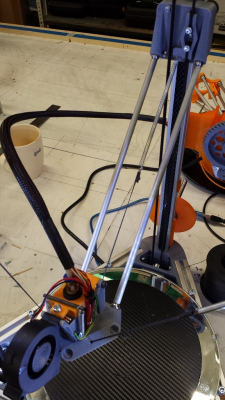
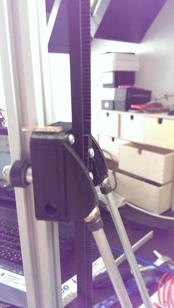
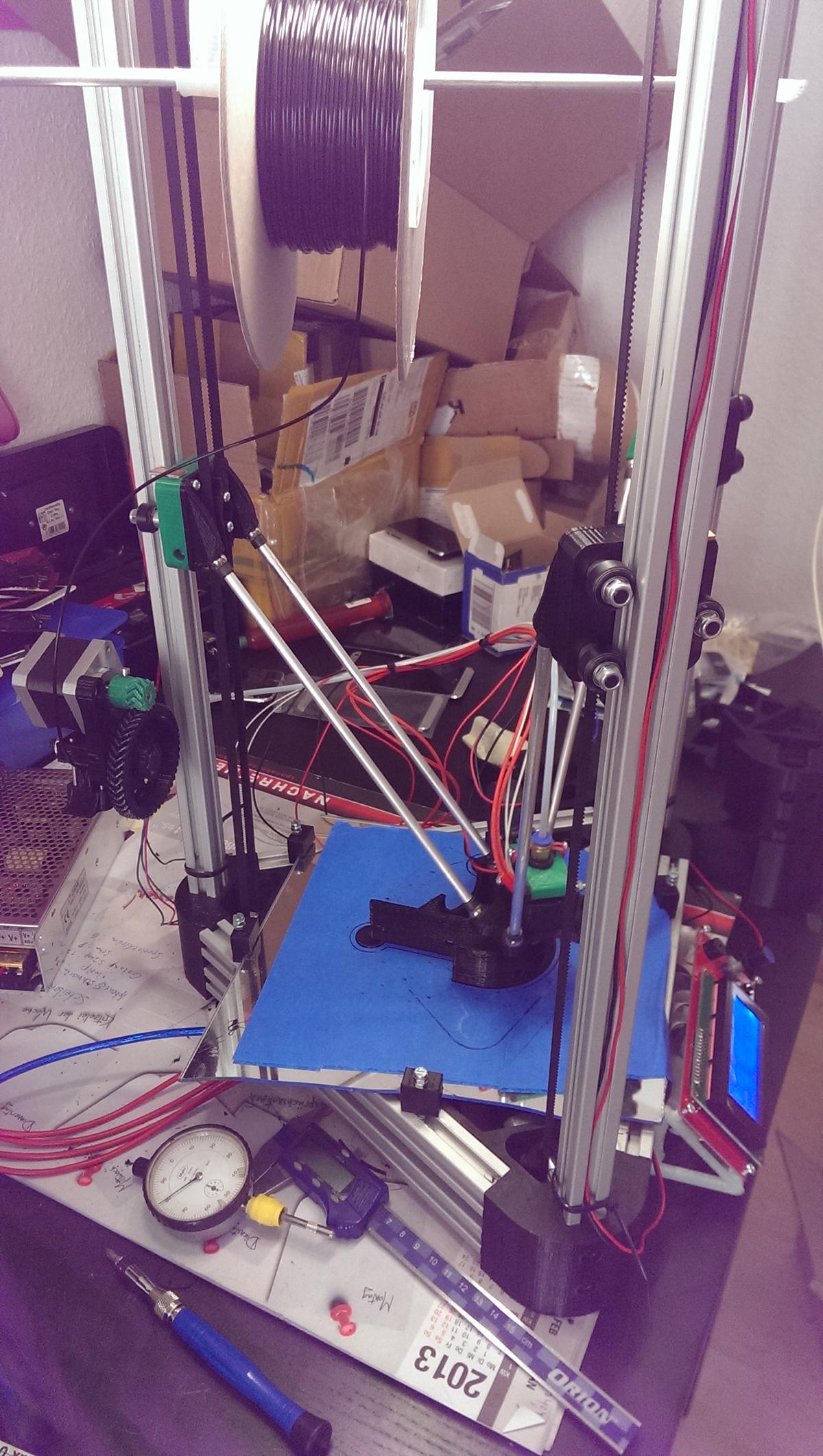
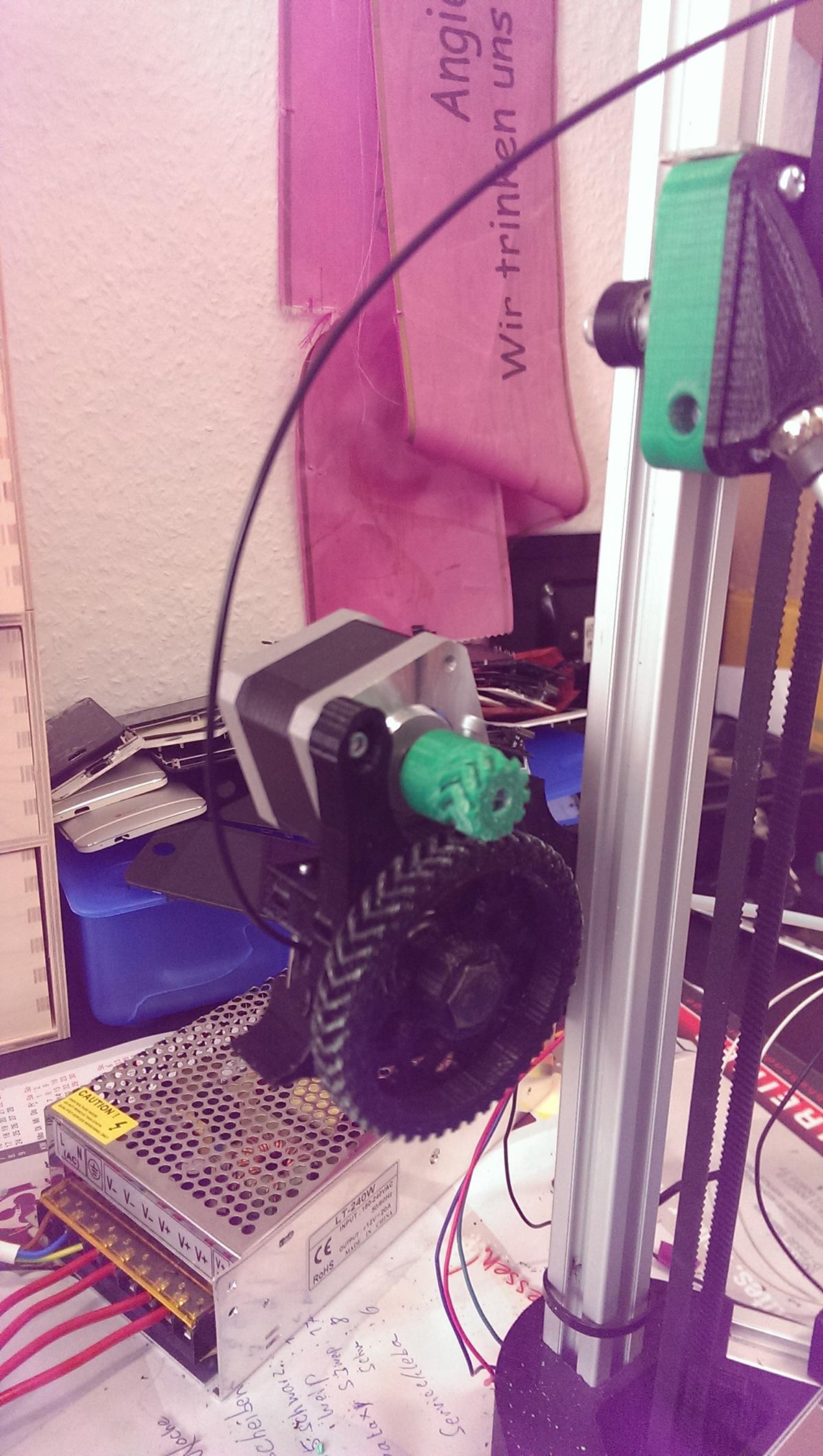
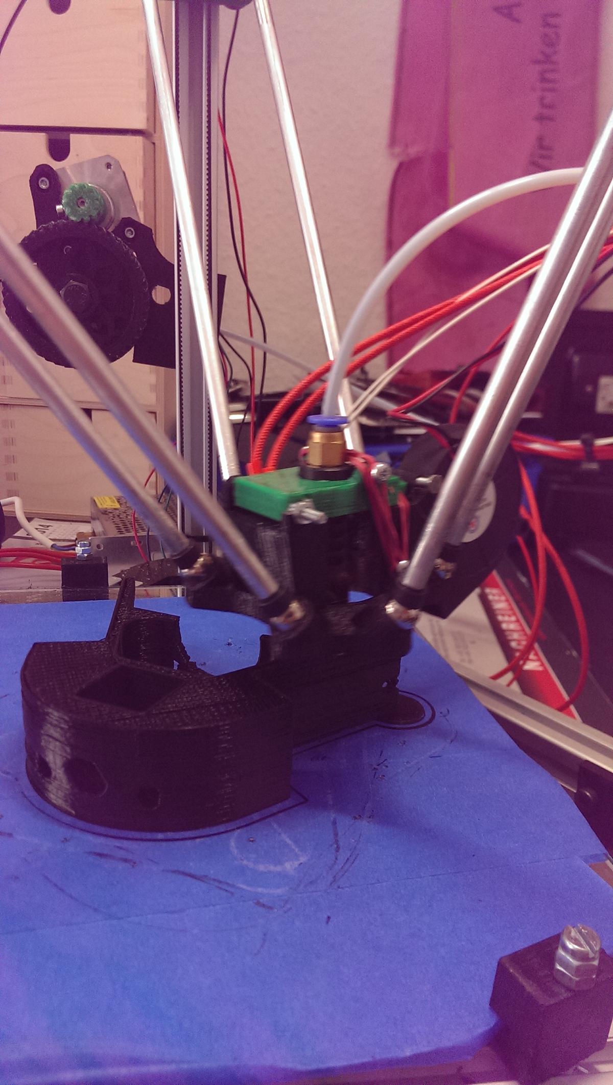
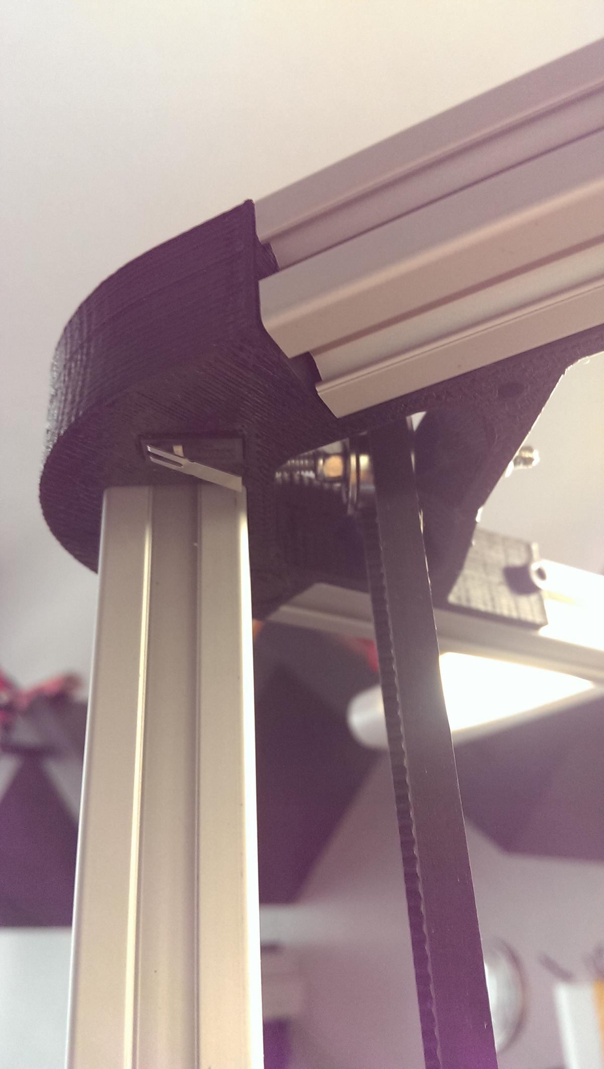
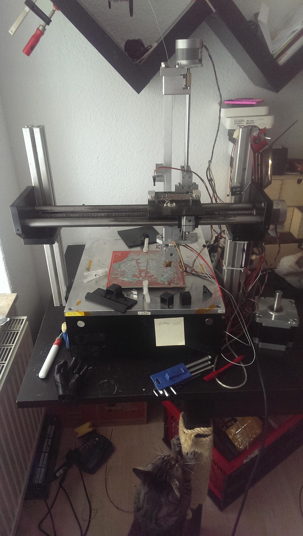
Hi here are a few pic´s of my cp and the repstrap who made it.
Is it possible to look in eeprom?
Is it possible to look in eeprom?
|
Re: Cherry Pi III Is Available August 01, 2014 07:59AM |
Registered: 10 years ago Posts: 515 |
|
Re: Cherry Pi III Is Available August 01, 2014 08:20AM |
Registered: 9 years ago Posts: 113 |
|
Re: Cherry Pi III Is Available August 01, 2014 10:15AM |
Registered: 9 years ago Posts: 20 |
Thank you,
i never used reptier till now, i think i have to. i readjusted my cp now with m666 its much easiear and safes a lot time i waste one week, if i have questions i ask you earlier.i print at the moment a cube, it looks like that the extruder make much steps (440) with the cherry pi III extruder. is it right that the disadvantage of eeprom is, when i upload another firmware to my arduino the configuration is lost or is my thinking wrong?
i never used reptier till now, i think i have to. i readjusted my cp now with m666 its much easiear and safes a lot time i waste one week, if i have questions i ask you earlier.i print at the moment a cube, it looks like that the extruder make much steps (440) with the cherry pi III extruder. is it right that the disadvantage of eeprom is, when i upload another firmware to my arduino the configuration is lost or is my thinking wrong?
|
Re: Cherry Pi III Is Available August 01, 2014 11:15AM |
Registered: 10 years ago Posts: 515 |
Quote
lines11
Thank you,
i never used reptier till now, i think i have to. i readjusted my cp now with m666 its much easiear and safes a lot time i waste one week, if i have questions i ask you earlier.i print at the moment a cube, it looks like that the extruder make much steps (440) with the cherry pi III extruder. is it right that the disadvantage of eeprom is, when i upload another firmware to my arduino the configuration is lost or is my thinking wrong?
I use Rich Cattell's Marlin from here [github.com]. I you load another configuration from the Arduino IDE the changes to anything in EEPROM won't take effect unless you issue an M502 (load factory defaults) and then save it with M500. This will overwrite all EEPROM values with the values in your new configuration. I run my steppers at 1/16 microstepping and have my extruder set to 640 steps/mm. You can change this with an M92 Ennn.nn command. M500 would save the new value to EEPROM. It's easy to check. Measure from the input on the extruder to 110mm back on your filament. Extrude 25mm four times using Repetier Host or Pronterface. Measure the distance between your mark and the extruder. This will tell you exactly how much was extruded. Using this you can work out what the new M92 Ennn.nn value shouyld be using (target length/actual length) x old M92 Ennn.nn value e,g if you actually extruded 90mm when you told the machine to extrude 100mm the formula is (100/90) x 640 (for me) = 711.1. So M92 E711.1 followed by M500 would set the correct steps per mm for the extruder.
Andy
|
Re: Cherry Pi III Is Available August 01, 2014 11:38AM |
Registered: 9 years ago Posts: 20 |
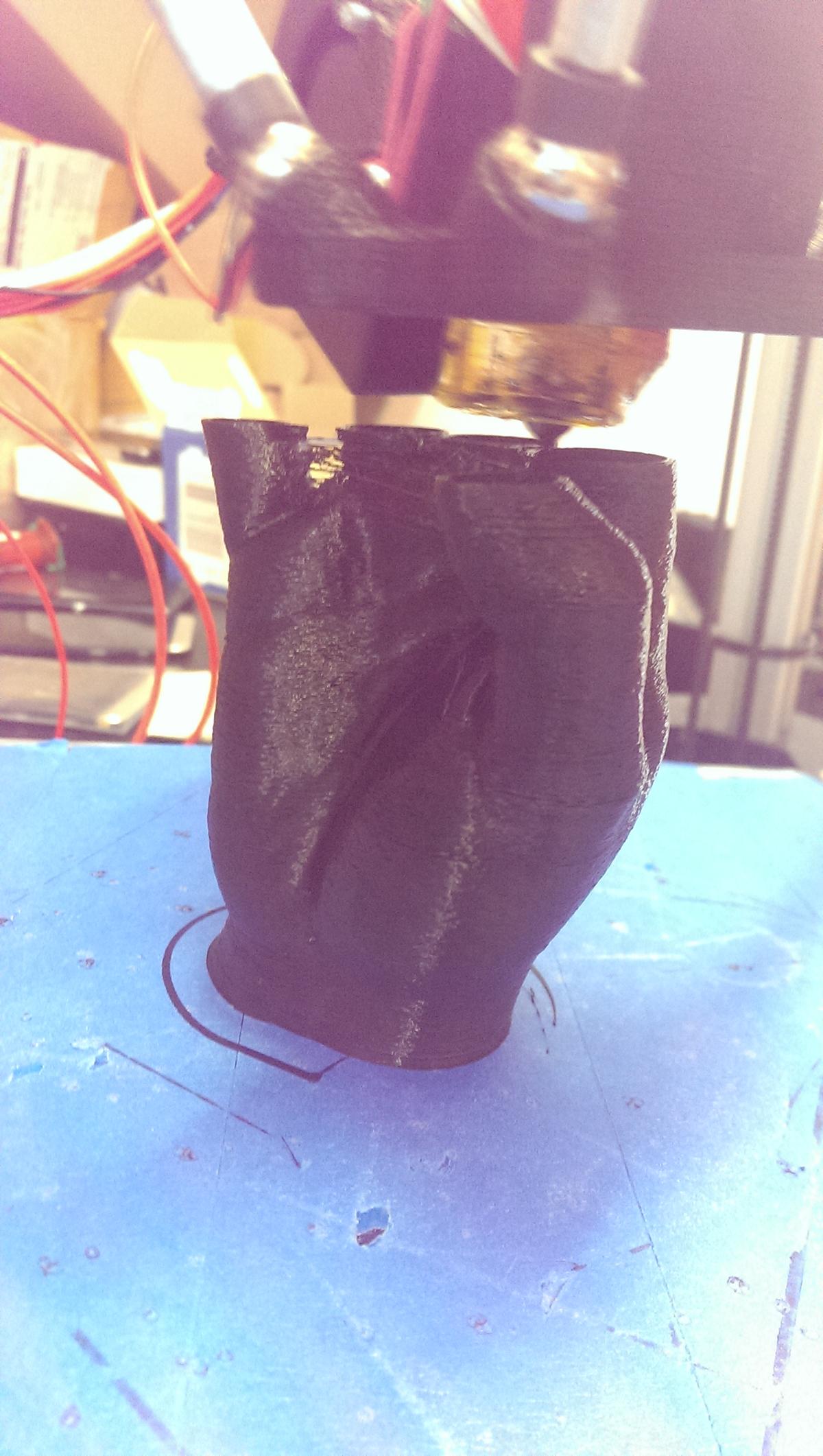
ok,
i now use rich cattel again. Nice to know that eeprom is not changing anithing. At the moment i print a hand from thingiverse looks good. not as good as my repstrap but 4 times faster. i have to google more about eeprom to understand it complete, but the endstop offset and the delta radius offset changes are working well. thank you for this information again. at the moment i pirnt without g29 (auto bed leveling) to test my settings.
i now use rich cattel again. Nice to know that eeprom is not changing anithing. At the moment i print a hand from thingiverse looks good. not as good as my repstrap but 4 times faster. i have to google more about eeprom to understand it complete, but the endstop offset and the delta radius offset changes are working well. thank you for this information again. at the moment i pirnt without g29 (auto bed leveling) to test my settings.


Sorry, only registered users may post in this forum.