Cherry Pi III Is Available
Posted by AndyCart
|
Re: Cherry Pi III Is Available October 11, 2014 11:13AM |
Registered: 9 years ago Posts: 111 |
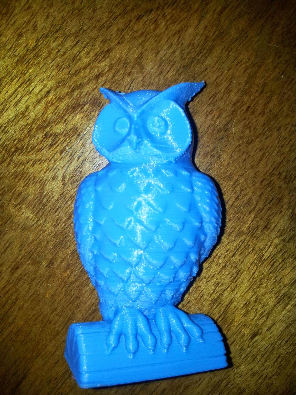
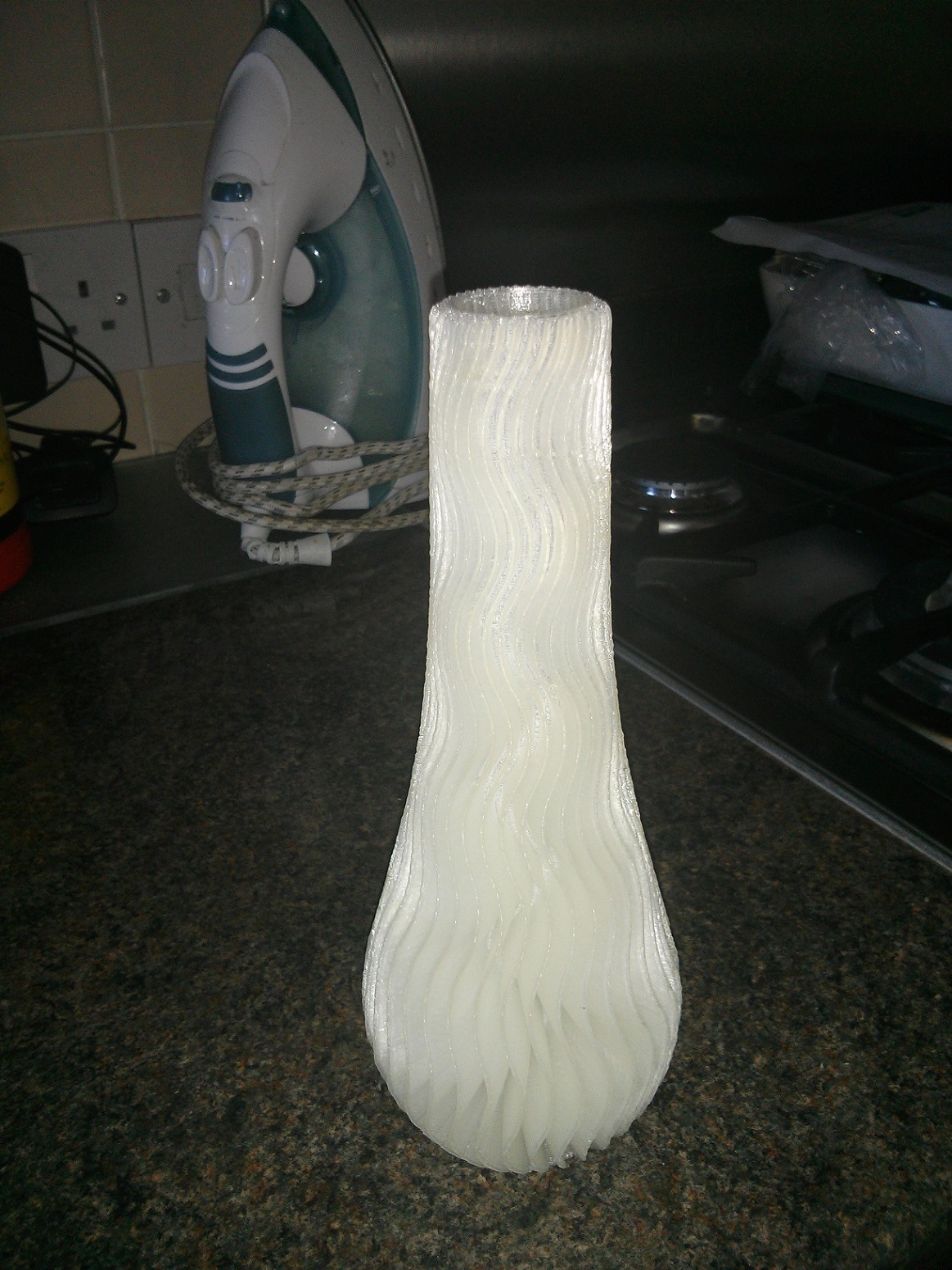
I received my cherry pi lll a few weeks ago and still playing with settings.Im impressed with its speed and quality.Andy has been very helpful with settings etc.Here are a few things I have printed,I still need to fine tune it.
I think the owl was at 0.2 and vase at 0.3 layer height.
I think the owl was at 0.2 and vase at 0.3 layer height.
|
Re: Cherry Pi III Is Available October 11, 2014 07:30PM |
Registered: 9 years ago Posts: 113 |
|
Re: Cherry Pi III Is Available October 12, 2014 05:33AM |
Registered: 10 years ago Posts: 515 |
Quote
nka
very nice! it's a good printer!
Andy (or someone else), I'll have to reprint the wheels carriage to match my spring loaded carriage. I have MISUMI extrusion, what version should I use?
Hi Sebastien
Use the original i.e not the V Slot version. Not sure how you will fare with the Misumi extrusion. It doesn't appear to have a V slot. Maybe someone else has used it and can advise. I use this extrusion [www.aluminium-profile.co.uk]
Andy
|
Re: Cherry Pi III Is Available October 12, 2014 05:45AM |
Registered: 10 years ago Posts: 903 |
Quote
nka
Andy (or someone else), I'll have to reprint the wheels carriage to match my spring loaded carriage. I have MISUMI extrusion, what version should I use?
http://forums.reprap.org/read.php?178,361141,409739#msg-409739
"For completeness of the discussion, Misumi 2020 has totally square-cut slots. The Mini-V wheels *barely* have any contact with the inside of the slot, and require a larger mounting plate (or a shim to pry the Bosch/Rexroth sized carriage open wider). Although they have not de-railed *yet* on my printer, I would say that the use of Misumi 2020 with the Mini-V wheels should be strongly discouraged."
With that said, I shimmed the original Bosch-Rexroth carriages open with popsicle sticks in the slots enough so that they worked. Nobody has done a carriage for Misumi yet because the wheels really do not fit properly.....
|
Re: Cherry Pi III Is Available October 12, 2014 08:36PM |
Registered: 9 years ago Posts: 113 |
|
Re: Cherry Pi III Is Available October 13, 2014 03:23AM |
Registered: 10 years ago Posts: 515 |
|
Re: Cherry Pi III Is Available October 13, 2014 06:06AM |
Registered: 10 years ago Posts: 903 |
Quote
AndyCart
Could you add a 45 degree chamfer on the slots with a square file?
http://3d.grabercars.com/?product=dual-623-wide-v-roller-fits-both-3mm-and-8mm-t-slot-extrusions
I was thinking that either the Grabercars wheels (specifies they work with Misumi 4040 but expensive) or mounting the mini-V wheels in a drill and taking a hair more off each side of the V with a file would be possible fixes. In my case, I have 2020 V-slot that I intend to salvage from my Mk1 RepStrap delta to do the job properly.....
|
Re: Cherry Pi III Is Available October 19, 2014 11:14PM |
Registered: 11 years ago Posts: 364 |
@andy
what is the size of springs you are using? I tried this on my 3dr ( made new carriages and micro platform ) .The problem i face is that if i hit the rods by mistake while adjusting something on the printer the rods pop out of the socket and then everything goes flying here and there. Is this normal or are my springs not strong enough?
what is the size of springs you are using? I tried this on my 3dr ( made new carriages and micro platform ) .The problem i face is that if i hit the rods by mistake while adjusting something on the printer the rods pop out of the socket and then everything goes flying here and there. Is this normal or are my springs not strong enough?
|
Re: Cherry Pi III Is Available October 20, 2014 02:30AM |
Registered: 10 years ago Posts: 515 |
Quote
ekaggrat
@andy
what is the size of springs you are using? I tried this on my 3dr ( made new carriages and micro platform ) .The problem i face is that if i hit the rods by mistake while adjusting something on the printer the rods pop out of the socket and then everything goes flying here and there. Is this normal or are my springs not strong enough?
The springs I use are 80mm, quite strong and I pull about 10mm of tension on them. This gives me a very solid attachment. I've only had the rods pop out once. My fault. I caused a serious head crash when I mis typed an M666 H value and accidentally added an extra 100mm to my Z height! You can see the springs on page 4 of this thread
Edited 1 time(s). Last edit at 10/20/2014 02:31AM by AndyCart.
|
Re: Cherry Pi III Is Available October 20, 2014 03:43AM |
Registered: 11 years ago Posts: 364 |
|
Re: Cherry Pi III Is Available October 20, 2014 11:16AM |
Registered: 10 years ago Posts: 515 |
|
Re: Cherry Pi III Is Available October 20, 2014 12:44PM |
Registered: 11 years ago Posts: 364 |
|
Re: Cherry Pi III Is Available October 20, 2014 01:24PM |
Registered: 9 years ago Posts: 113 |
|
Re: Cherry Pi III Is Available October 25, 2014 08:20PM |
Registered: 9 years ago Posts: 164 |
Mine is nearly together! Just need to install the extrusion module and wire the associated connections. Unfortunately my clumsiness cost me one of my microswitches so that won't happen for a couple of days. Everything else is looking good with only a few hiccups. I still need to find a build plate (I tried cutting glass for the first time... fun but I still need to find a build plate haha).
How did you guys determine how much tension was appropriate for the drive belts? I think mine have a nice amount but it's hard to describe... They don't have much slack at all, but they're not so tight as that they might cause the tower caps to creep down over time.
I think the only way I'm really deviating from the original design is that I'm not going to pass the wiring for the extruder/feeder through the extrusion; I'm just going to run it under. Is there any issue with that or was there a specific reason (other than aesthetics) that they pass through the extrusion in the original design?
While I'm here, is there anything I should keep in mind for wiring? From the perspective of looking toward the LCD screen, I've assigned the tower on the left as X, the tower on the right as Y, and the tower at the back (with the extruder stepper) as Z. I think my main concerns are a) have I assigned the right positions for the microswitches (are they connected to the min or max pins?), and b) if I've wired my steppers correctly (everything I've seen seems to indicate that the wires are in the same order leaving the steppers as they are entering the board... for example, looking at the stepper motor connector on the motor, it might go green, red, grey, yellow, and on the RAMPS board they enter the receptacle in that order too).
EDIT: I've tried creating a new set of arms too and these seem much more equal length, so I'll give them a shot. Carbon still seemed to be the way to go for economy reasons.
Edited 1 time(s). Last edit at 10/25/2014 08:22PM by pugzor.
|
Re: Cherry Pi III Is Available October 26, 2014 02:20AM |
Registered: 10 years ago Posts: 515 |
Quote
pugzor
Mine is nearly together! Just need to install the extrusion module and wire the associated connections. Unfortunately my clumsiness cost me one of my microswitches so that won't happen for a couple of days. Everything else is looking good with only a few hiccups. I still need to find a build plate (I tried cutting glass for the first time... fun but I still need to find a build plate haha).
How did you guys determine how much tension was appropriate for the drive belts? I think mine have a nice amount but it's hard to describe... They don't have much slack at all, but they're not so tight as that they might cause the tower caps to creep down over time.
I think the only way I'm really deviating from the original design is that I'm not going to pass the wiring for the extruder/feeder through the extrusion; I'm just going to run it under. Is there any issue with that or was there a specific reason (other than aesthetics) that they pass through the extrusion in the original design?
While I'm here, is there anything I should keep in mind for wiring? From the perspective of looking toward the LCD screen, I've assigned the tower on the left as X, the tower on the right as Y, and the tower at the back (with the extruder stepper) as Z. I think my main concerns are a) have I assigned the right positions for the microswitches (are they connected to the min or max pins?), and b) if I've wired my steppers correctly (everything I've seen seems to indicate that the wires are in the same order leaving the steppers as they are entering the board... for example, looking at the stepper motor connector on the motor, it might go green, red, grey, yellow, and on the RAMPS board they enter the receptacle in that order too).
EDIT: I've tried creating a new set of arms too and these seem much more equal length, so I'll give them a shot. Carbon still seemed to be the way to go for economy reasons.
For a build plate search on Ebay/Amazon for mirror plates for candles they are usually 6mm thick and seemed to be toughened glass. In the UK a 250mm diameter one is about £5.
Belts don't need to be so tight that they sound a musical note if you pluck them but they don't want to be too slack either
There's no design reason to take the wires through the extrusion, purely aesthetic.
You have your tower designations correct. You need to use the max endstop connectors for X, Y and Z and the Z min connector for the effector probe microswitch
The stepper wiring doesn't matter as long as you get the correct pairs. If all the cables from the motor are disconnected it should be easy to spin the shaft by hand. Connect two wires together, spin the shaft again, if it's just as easy to turn those wires aren't a pair. If it's suddenly much harder to turn, and feels 'notchy' then you have a pair. The connectors on RAMPS are designated 2B 2A 1A 1B the numbers designate the pair so connect one of your motor pairs to the 2's and one to the 1's. It doesn't matter, at this stage which is which but make sure all your motors connect the same way (you have half a chance of getting it correct) if a motor spins the wrong way (carriage goes up instead of down, etc) then just pull the plug off RAMPS for that motor (after disconnecting the power!) and turn it through 180 degrees. It will now spin the correct way, or you could invert the motor in Marlin.
Good luck. Let's have a 'first print' video on Youtube

Andy
Edited 1 time(s). Last edit at 10/26/2014 02:21AM by AndyCart.
|
Re: Cherry Pi III Is Available October 26, 2014 08:37AM |
Registered: 9 years ago Posts: 164 |
Awesome, thanks for that Andy!
Actually just dug up a build plate then (4mm thick mirror, 250mm round, beveled edges) which I hope will be fine. If required I might get something else to adhere to the bottom of it to strengthen it a bit... here's hoping the 4mm is fine though. I'd looked on eBay previously without luck. Might have been looking for glass and not mirror.. who knows.
Thanks for the tips on RAMPS too. There's so much info out there on it but I've struggled finding stuff specific to deltas. I mean, I could always make educated guesses, but it's a lot less stuffing around if I just ask on here.
Good news is that I didn't actually break my microswitch haha! I thought I'd broken the lever but ends up they actually are just held in there and can be removed with a slight bit of force, but also inserted again without difficulty. Even though we're playing with home made deltas I still get impressed by the precision of small components like that.
Build plate will be here in 2 days and hopefully the filament isn't far off! Maybe a calibration video might be required haha.
Oh, the only other question I have is... after looking through some of the config files for Marlin, will I need to measure precisely the full length of the delta rods? I think I recall seeing a measurement of 238.4mm or similar, but I only have a tiny 200mm set of digital verniers. Is there anything else a bit tricky that I will need to do for the config?
Actually just dug up a build plate then (4mm thick mirror, 250mm round, beveled edges) which I hope will be fine. If required I might get something else to adhere to the bottom of it to strengthen it a bit... here's hoping the 4mm is fine though. I'd looked on eBay previously without luck. Might have been looking for glass and not mirror.. who knows.
Thanks for the tips on RAMPS too. There's so much info out there on it but I've struggled finding stuff specific to deltas. I mean, I could always make educated guesses, but it's a lot less stuffing around if I just ask on here.
Good news is that I didn't actually break my microswitch haha! I thought I'd broken the lever but ends up they actually are just held in there and can be removed with a slight bit of force, but also inserted again without difficulty. Even though we're playing with home made deltas I still get impressed by the precision of small components like that.
Build plate will be here in 2 days and hopefully the filament isn't far off! Maybe a calibration video might be required haha.
Oh, the only other question I have is... after looking through some of the config files for Marlin, will I need to measure precisely the full length of the delta rods? I think I recall seeing a measurement of 238.4mm or similar, but I only have a tiny 200mm set of digital verniers.
Is there anything else a bit tricky that I will need to do for the config?
|
Re: Cherry Pi III Is Available October 26, 2014 09:50AM |
Registered: 11 years ago Posts: 364 |
|
Re: Cherry Pi III Is Available October 26, 2014 09:50AM |
Registered: 10 years ago Posts: 515 |
For the length of the delta rods just do the best you can with a good ruler. You will invariably need to tweak the value when you commission anyway. It's the delta rod length that governs the size of your printed parts in the X & Y dimensions. It's very rarely what the rods actually are!
|
Re: Cherry Pi III Is Available October 26, 2014 06:42PM |
Registered: 10 years ago Posts: 515 |
|
Re: Cherry Pi III Is Available October 26, 2014 10:23PM |
Registered: 11 years ago Posts: 364 |
@andy
sure they do. The simplicity is just amazing. Only time will tell how long they last. The reason i converted to this was that the trarrax joints had some backlash in them which when tension-ed with springs made them unequal. This made the micro platform rock side to side. Interestingly though between the trarrax joints and this system i didn't see much change in print quality. The biggest difference it made was that i was getting unequal x and y dimensions ( 0.3 mm difference in a 20mm cube ) due to the backlash , which is now gone...
thanks for the great joint system ( it can be applied in a lot more other places also ) ..
|
Re: Cherry Pi III Is Available November 01, 2014 12:57AM |
Registered: 9 years ago Posts: 164 |

So, it appears I've got my CP3 assembled. But there's a problem... I'm finding it difficult to figure out WTF to do with software to drive it, haha.
I've managed to get Arduino IDE and load up Rich Cartell's Marlin, as well as your config file AndyCart (I reckon it's going to be a lot closer to mine than what anything else is), but I have no idea on next steps. How do I send it commands to execute? What in your config file will I actually need to adjust Andy? If I can get answers to those two questions I should have a first print video up within hours...
EDIT: Yes, I have bright pink colorfabb filament. while I'm learning about what works and what doesn't, toys for my daughter seemed like a good idea...
Oh, out of interest, where has everyone spliced in their extruder fan? I was hoping the 2nd power supply port on RAMPS 1.4 was in parallel with the other one, but alas, it was not...
Edited 1 time(s). Last edit at 11/01/2014 12:59AM by pugzor.
|
Re: Cherry Pi III Is Available November 01, 2014 01:49AM |
Registered: 10 years ago Posts: 515 |
Wow. That looks terrific!
You need to connect to a host program to send gcode commands to the machine. I use Repetier Host in 'expert' mode but I know lots of people use Pronterface. They are both free. Just Google them.
In terms of what to adjust, if you run an M666 L it will list the available things you can tweak directly from the host and then save back to EEPROM with M500.
Run an auto calibration with G30 A and it will pretty much set itself up. I normally give it a bit of help by roughly calibrating by adjusting the end stop offsets (with M666 X, Y and Z) and the Z height ( with M666 H)
The part cooling fan connects to D9 on RAMPS. If you have a separate hot-end cooling fan alla E3D V6 then wire it direct to your 12V supply. The second power in connector is for a heated bed psu.
Good luck
Andy
|
Re: Cherry Pi III Is Available November 01, 2014 07:24AM |
Registered: 9 years ago Posts: 164 |
Wicked. Glad I checked with the board before I powered it up. Connected it up to D9.
Unfortunately it seems I'm having comms problems though. I've been playing with com ports and baud rates but nothing seems to be sticking. I can flash the firmware fine but giving it commands isn't doing anything. It just says "x Command Waiting" where x can be any number of commands I try to give it.
Anyway, while I'm trying to figure it out, here's a couple more pics of my handy work. Could have done a better job but I'm expecting to have to deconstruct it to repair %@#^ ups.
Unfortunately it seems I'm having comms problems though. I've been playing with com ports and baud rates but nothing seems to be sticking.
I can flash the firmware fine but giving it commands isn't doing anything. It just says "x Command Waiting" where x can be any number of commands I try to give it. Anyway, while I'm trying to figure it out, here's a couple more pics of my handy work. Could have done a better job but I'm expecting to have to deconstruct it to repair %@#^ ups.


|
Re: Cherry Pi III Is Available November 01, 2014 10:00AM |
Registered: 9 years ago Posts: 113 |
make sure Arduino IDE is closed when you connect to the printer with the 3D Printer Software, as there can only be one connexion to the serial port at the same time. Make sure you are connected at the right baud rate (defined in the conf.h) or try to lower it to 19200.
- Sebastien Plante (nka)
- Sebastien Plante (nka)
|
Re: Cherry Pi III Is Available November 01, 2014 12:44PM |
Registered: 10 years ago Posts: 515 |
|
Re: Cherry Pi III Is Available November 01, 2014 05:54PM |
Registered: 9 years ago Posts: 164 |
|
Re: Cherry Pi III Is Available November 02, 2014 01:07AM |
Registered: 10 years ago Posts: 515 |
|
Re: Cherry Pi III Is Available November 02, 2014 01:11AM |
Registered: 9 years ago Posts: 164 |
Win 8.1 on an Asus laptop. I've made sure it's on COM1 with a baud rate of 115200 (since that's what the config file seems to point to), and have confirmed that these settings are consistent in Arduino IDE and Repetier.
I've been playing with it for about 3 hours now, so I'm pretty much ready to sell it already haha.
I've been playing with it for about 3 hours now, so I'm pretty much ready to sell it already haha.
|
Re: Cherry Pi III Is Available November 02, 2014 03:10AM |
Registered: 10 years ago Posts: 515 |
If you have successfully flashed the firmware from Arduino IDE to the Mega2560 then that baud rate and COM port must be the correct ones. I have had issues previously with Repetier Host refusing to connect. Have you tried Pronterface as the host? It seems much more forgiving of differing set ups. It should at least get you to a point where commands can be sent to your machine
As a double check right click My Computer and select Manage from there select Device Manager and open the COM Ports with your Arduino connected you should see an entry for it and the COM port that Windows has allocated to it. COM1 doesn't sound right. Windows normally reserves 1, 2, 3 & 4 for hardware COM ports
Edited 2 time(s). Last edit at 11/02/2014 03:15AM by AndyCart.
|
Re: Cherry Pi III Is Available November 02, 2014 03:35AM |
Registered: 9 years ago Posts: 164 |
That's a bit concerning then, because I've been able to update the firmware through Arduino IDE several times without issue. Originally windows allocated COM3 but I saw references to 'serial port 1' in the code, so I force changed it to COM1 since it wasn't in use. I might try changing it to COM5 or something when I get home and try that.
I've used Repetier, Pronterface and Matter Control all without luck. I can tell they're connecting on some level because the lcd flickers a bit when I initialise a connection. Just... It doesn't seem to go anywhere! I think it's frustratingly close to working...
I've used Repetier, Pronterface and Matter Control all without luck. I can tell they're connecting on some level because the lcd flickers a bit when I initialise a connection. Just... It doesn't seem to go anywhere! I think it's frustratingly close to working...


Sorry, only registered users may post in this forum.