Cherry Pi III Is Available
Posted by AndyCart
|
Re: Cherry Pi III Is Available November 09, 2015 02:53PM |
Registered: 10 years ago Posts: 40 |
It helped!
Thank you very much!
Does this makes the firmware do harder work calculating the motion?
I know there are some defines for sin and cos angles, do I need to add more?
I'm using MEGA2560 and sometimes I can see that I push it to its limits already when there are too many segments.
Thank you very much!
Does this makes the firmware do harder work calculating the motion?
I know there are some defines for sin and cos angles, do I need to add more?
I'm using MEGA2560 and sometimes I can see that I push it to its limits already when there are too many segments.
|
Re: Cherry Pi III Is Available November 25, 2015 03:01PM |
Registered: 10 years ago Posts: 155 |
Hi Andy and others,
So I have tried my best to build my cherry pie as accurately as possible and I guess now it's time to power up the electronics and calibrate etc. Now I have a couple of questions. I'm new to delta printers but from what I've read in the thread is when I use the LJ12A3-4-Z/BY sensor together with Rich Cattels' Marlin from the test branch on github, I'm ready to start the calibration process? Or do I have to set things manually first? I've not yet installed the hotend. Is that a problem?
Thanks much in advance,
Niles
|
Re: Cherry Pi III Is Available November 26, 2015 01:24AM |
Registered: 10 years ago Posts: 515 |
Hi Niles
It sounds like you are pretty much good to go. Your machine should calibrate quite happily without the hotend but when you fit one post calibration you will have to adjust Z height manually to suit. Make sure all 4 limit switches, X, Y, Z and Z min (your prox sensor) are operating correctly before you issue the G30 A command.
Good luck.
Andy
|
Re: Cherry Pi III Is Available November 26, 2015 06:51AM |
Registered: 10 years ago Posts: 155 |
Thanks very much Andy,
I do have to add that I use different nylon/delrin wheels than the mini v's from Openbuilds. This means that my rod carriages sit a little bit closer to the profile towers. I'm also using a different construction for the rods since I couldn't find drilled 8 mm ball joints. I figured that the latest cherry pi's rod length including the balls is around 241 mm? (225 mm tubes + 2 x 8 mm balls). Does the firmware calibration account for possible slight deviations from the original Cherry Pi IIIS?
Niles
Edited 1 time(s). Last edit at 11/26/2015 08:15AM by Nilez.
|
Re: Cherry Pi III Is Available November 30, 2015 06:13PM |
Registered: 11 years ago Posts: 40 |
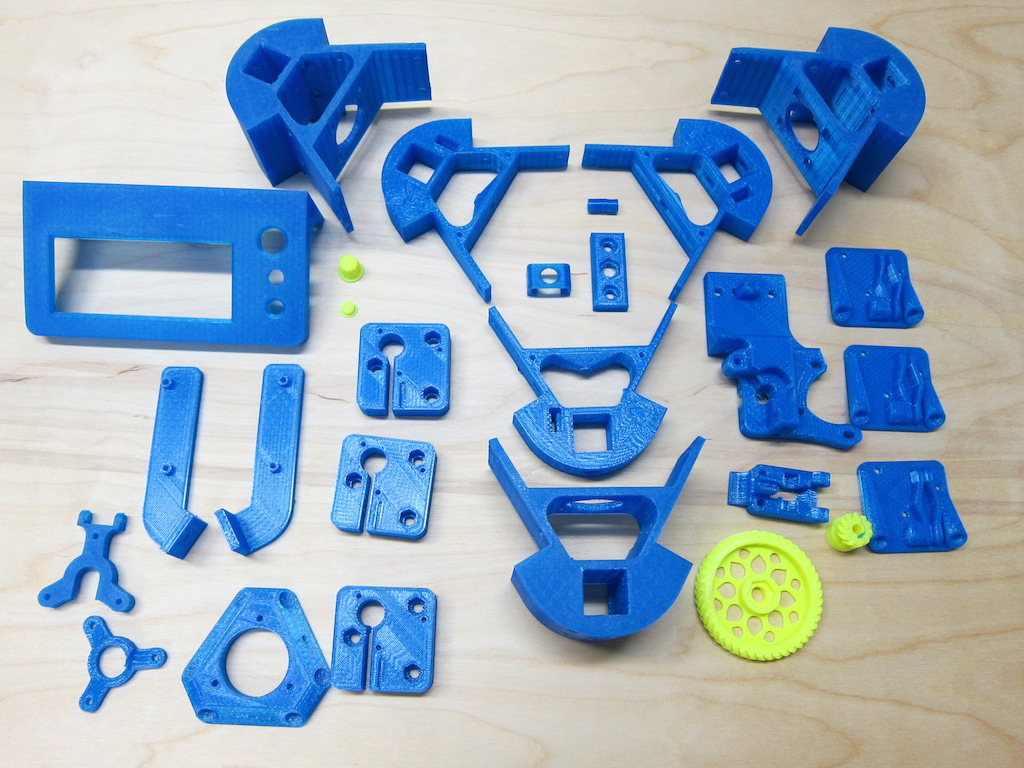
I've printed my parts, and am waiting for hardware and electronics.
I've used the IIIs parts, with substitutions from this thread for E3D clone effector, and OpenBuilds extrusions.
I've read through this entire thread, and appreciate all the input. Thanks for all the hard work; especially the original design.
I have a few questions:
* what is the 'extruder insert' part for?
* I've printed the effector base in PLA; I understand ABS is recommended, but can't conveniently print it. Am I going to be okay?
-Matt
|
Re: Cherry Pi III Is Available November 30, 2015 07:04PM |
Registered: 10 years ago Posts: 155 |
Hi Matt,
I was wondering about the "insert" too. Maybe considering the dimensions it is a printable idler bearing axle that sits in the slot of the "extruder guider" part. Don't know what the hole in the part would be for though. About the PLA effector, I don't think you'll be able to print with that for very long. But maybe just long enough to print an abs version with your Cherry Pi. Have you tried glue stick on glass? Worked as a solution for me if warping was also your problem with the ABS print.
Edited 1 time(s). Last edit at 11/30/2015 07:08PM by Nilez.
|
Re: Cherry Pi III Is Available December 01, 2015 04:45AM |
Registered: 10 years ago Posts: 515 |
|
Re: Cherry Pi III Is Available December 06, 2015 04:49AM |
Registered: 11 years ago Posts: 40 |
I'm thinking about which version of Marlin to use.
I saw the earlier post about "Rich Cattell's new Marlin version" [forums.reprap.org]
But the comments suggest that his changes all have to do with auto-leveling. I'm planning to skip that for now.
If _not_ using auto-level, is there any advantage to Cattell's fork (vs the mainline Marlin branch)?
-Matt
|
Re: Cherry Pi III Is Available January 24, 2016 10:04PM |
Registered: 11 years ago Posts: 40 |
My newly complete Cherry PI IIIs, with various modifications from this thread.
Uses RAMPS with Marlin 1.1.0 RC3. I had to patch a line to get M666 to work properly; will document that soon.
Still not completely dialed in, but I couldn't resist trying something real.
I have a heatbed on order; gluestick is too much of a PITA.
Manual configuration wasn't too tough, once I got Marlin fixed.
Video: [www.youtube.com]
Many thanks to Andy for a terrific design, and the rest of you for all your info in this thread.
-Matt
Edited 1 time(s). Last edit at 01/24/2016 10:04PM by mkeveney.
Uses RAMPS with Marlin 1.1.0 RC3. I had to patch a line to get M666 to work properly; will document that soon.
Still not completely dialed in, but I couldn't resist trying something real.
I have a heatbed on order; gluestick is too much of a PITA.
Manual configuration wasn't too tough, once I got Marlin fixed.
Video: [www.youtube.com]


Many thanks to Andy for a terrific design, and the rest of you for all your info in this thread.
-Matt
Edited 1 time(s). Last edit at 01/24/2016 10:04PM by mkeveney.
|
Re: Cherry Pi III Is Available January 25, 2016 05:52AM |
Registered: 10 years ago Posts: 515 |
|
Re: Cherry Pi III Is Available February 12, 2016 05:00AM |
Registered: 8 years ago Posts: 1 |
|
Re: Cherry Pi III Is Available February 12, 2016 12:38PM |
Registered: 8 years ago Posts: 2 |
Hello everyone! This is my first post on here -- greetings from a wet and dreary Finland.
First off, a very big thanks to AndyCart for a very smart delta implementation. I stumbled across the Cherry Pi after I started thinking about building a delta printer to complement my Turnigy Fabrikator.
I have most of the required parts handy, just need to get me some alu tube and springs while I wait for the 8mm balls to arrive (decided to drill the 4mm holes myself, as the linked stop motion balls are actually quite expensive to be shipped here... I have a bench drill, so I'll just fabricate a drilling jig using this instructable: [www.instructables.com])
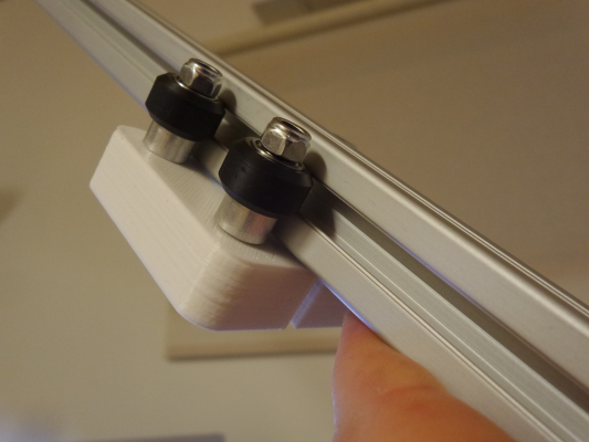
I am going to build the frame with some 2020 "B-type" extrusion from Motedis, and after printing the carriage for a preliminary test, I can confirm that the stock carriages and small delrin wheels work nicely with this extrusion (see image below)
Anyway, I have a question: I have some 2040 extrusion that I need to use up (It doesn't work in the OX CNC I was going to build, as I need proper V-slot for that), so I was wondering whether I could use the 2040 as the base triangle for the Cherry Pi build? Can I just use any delta printer foot model on e.g. Thingiverse, or will I run into possible problems, such as belt alignment?
Thanks in advance!
First off, a very big thanks to AndyCart for a very smart delta implementation. I stumbled across the Cherry Pi after I started thinking about building a delta printer to complement my Turnigy Fabrikator.
I have most of the required parts handy, just need to get me some alu tube and springs while I wait for the 8mm balls to arrive (decided to drill the 4mm holes myself, as the linked stop motion balls are actually quite expensive to be shipped here... I have a bench drill, so I'll just fabricate a drilling jig using this instructable: [www.instructables.com])
I am going to build the frame with some 2020 "B-type" extrusion from Motedis, and after printing the carriage for a preliminary test, I can confirm that the stock carriages and small delrin wheels work nicely with this extrusion (see image below)
Anyway, I have a question: I have some 2040 extrusion that I need to use up (It doesn't work in the OX CNC I was going to build, as I need proper V-slot for that), so I was wondering whether I could use the 2040 as the base triangle for the Cherry Pi build? Can I just use any delta printer foot model on e.g. Thingiverse, or will I run into possible problems, such as belt alignment?
Thanks in advance!
|
Re: Cherry Pi III Is Available February 12, 2016 12:49PM |
Registered: 9 years ago Posts: 1,159 |
Quote
yawk-oh
Hello everyone! This is my first post on here -- greetings from a wet and dreary Finland.
First off, a very big thanks to AndyCart for a very smart delta implementation. I stumbled across the Cherry Pi after I started thinking about building a delta printer to complement my Turnigy Fabrikator.
I have most of the required parts handy, just need to get me some alu tube and springs while I wait for the 8mm balls to arrive (decided to drill the 4mm holes myself, as the linked stop motion balls are actually quite expensive to be shipped here... I have a bench drill, so I'll just fabricate a drilling jig using this instructable: [www.instructables.com])
I am going to build the frame with some 2020 "B-type" extrusion from Motedis, and after printing the carriage for a preliminary test, I can confirm that the stock carriages and small delrin wheels work nicely with this extrusion (see image below)
Anyway, I have a question: I have some 2040 extrusion that I need to use up (It doesn't work in the OX CNC I was going to build, as I need proper V-slot for that), so I was wondering whether I could use the 2040 as the base triangle for the Cherry Pi build? Can I just use any delta printer foot model on e.g. Thingiverse, or will I run into possible problems, such as belt alignment?
Thanks in advance!
No don't think you will be able to but if they are long enough why not look at using them for the Verticals (Andy did a XL Version which is exactly that) it would still use the carriages you have. See Bigger Pi
You could also use mini Kossel top and bottom brakes for 20x20 if you wish that would work I think.
AS for 10mm balls PM me you address and I will gladly send you some FOC. I have maybe 15 spares 10mm dia drilled and tapped M4 use a M4 setscrew as a shaft and glue that into your tube be it Aluminium or Carbon Fibre.
Doug
Edited 2 time(s). Last edit at 02/12/2016 01:23PM by dougal1957.
|
Re: Cherry Pi III Is Available February 12, 2016 12:51PM |
Registered: 9 years ago Posts: 67 |
|
Re: Cherry Pi III Is Available February 12, 2016 01:19PM |
Registered: 10 years ago Posts: 515 |
Quote
SnmG
Hi Andy,
great Job
I have a question. Do you have any instruction for Cherry Pi iii ? Or do you know where I can get some more information about the instructions / first steps ? (videos, documentations...)
I would be very glad about more information.
Kind regards,
Sinem
All the info you need is in this thread and on Thingiverse
|
Re: Cherry Pi III Is Available February 12, 2016 01:31PM |
Registered: 8 years ago Posts: 2 |
Thanks for the responses, that's very helpful. I guess I have to drop the idea of using the 2040 and just go with the stock build, as the 2040 I got is not the "B" type and the slot is incompatible with the delrin wheels, unfortunately.
Doug, that's certainly a very generous offer! I will PM you
Doug, that's certainly a very generous offer! I will PM you
|
Re: Cherry Pi III Is Available March 31, 2016 03:40AM |
Registered: 10 years ago Posts: 44 |
My Updated Pi!
Initially built it about a year ago, had issues (self inflicted) with the carriages and other mechanisms, have since revisited the project and upgraded the motors, end stops, hot end mounting and cooling,
Youtubishness
Currently it's printing beautifully as low as .15mm with an E3D V6. There is a 92mm fan on the rear right cooling the Ramps.
Enjoy!
Edited 1 time(s). Last edit at 03/31/2016 03:45AM by Zzyzxx71.
|
Re: Cherry Pi III Is Available April 19, 2016 03:55PM |
Registered: 11 years ago Posts: 40 |
Delta Calibration with Escher3D calculator.
Hi gang.
My Cherry PI has been printing for a while, but I've been struggling over the last few weeks to get it really dialed in. I built and measured everything as carefully as I can, but I could still only print on center 100mm or so. I could not get the nozzle to track the whole bed reliably.
In my frustration I installed an inductive probe and tried Cattel's auto calibrator (testing fork) without success.
Finally I discovered this site:
[escher3d.com]
It does the same math used in the ARM-based RepRapFirmware, but spits out the numbers to be manually installed in other firmware types, including those that run on low-computing-power hardware like RAMPS. I used Cattel's fork, simply because it has convenient way to enter the tower rotation parameters, which were key in my case. (The latest Marlin 1.1 fork has most of the support under the hood, but maddeningly does not expose it in M665/666).
I followed the steps listed on the calculator page. Step 5 instructs us to 'measure the nozzle height errors' which is a bit light on specifics, perhaps because printers and firmware types vary. In more detail, here's the method I used:
Get your printer geometry ready. For my CherryPI, I used:
Diagonal rod 230
Delta radius 123
Homed height 250
- these are the same values in my configuration.h
The homed height is deliberately a bit smaller than measured, to ensure that our first pass doesn't crash into the bed.
Leave endstops and angular corrections zero
printable radius 90 (you might be able to go a smidge higher)
probe points 10
factors 6
* Click the 'suggest points' button. The first 6 points are at 12, 2, 4, 6, 8, and 10 o'clock on the radius you entered. The next three are at 12, 4, and 8 o'clock on half that radius. The final point is at the center.
* Program buttons in Pronterface to move to these X, Y points at Z = 5mm. You'll have to measure all these points at least three times, so I think it's worth the trouble to make the buttons. For example, my 'point 2' button is programmed to:
g0 F8000 x77.94 y-45 z5
* For convenience, I programmed another button to issue M114 (get position) followed by G28 (home all).
* Measure each point like so:
- Click the corresponding button you just programmed. The head will move to a point just above the measurement point.
- With a paper feeler gage ready, use the Z move buttons to sneak down to the bed.** As soon as it drags, click your 'get position' button or enter M114. Then click home.
- Negate the Z position reported by M114 to get the value to punch into the calculator.
* When all points are entered, click calculate. It spits out the M666 command for you. Copy & paste that into Pronterface; then enter M500 and M501 to save the values to EEPROM.
* Click 'copy to initial parameters' which enters those same M666 values into the top fields of the calculator to prepare for the next pass.
* Repeat the last 3 steps once more.
* Repeat the measurement step again. This time, you'll probably notice that your measurements are very close. Mine were all within .2mm, so I didn't bother going any further. I suppose you could keep going and see if it converges any more.
* Save the results of the last M501 command (or issue M503), in a text file somewhere, in case you have to restore your EEPROM.
That's it! While it might sound laborious, I found it faster and more accurate than anything else I've tried. If you're struggling as I was, give it a shot!
-Matt
** I actually created two 'micromove' buttons that move up and down by 0.02 mm to make this step more accurate. I'm not sure how much accuracy it really adds: the minimum theoretical microstep move is 0.0125, and microstepping is generally not as accurate in practice as in theory. Also, the M114 command reports back only two decimal places. Still, if you want to try it my way, here are the commands:
microdown:
G91
G0 Z-0.02 F3000
G90
microup:
G91
G0 Z0.02 F3000
G90
|
Re: Cherry Pi III Is Available July 24, 2016 06:14AM |
Registered: 10 years ago Posts: 327 |
As it's well over a year since I started my CP III, I think it's time to dust of the cobwebs and get it finished. 
From memory it's pretty much ready to go, I just have to fit the heated bed and finish the new belt driven extruder. I also remember it being a real pain to calibrate, so I think a Z probe is in order, After catching up with 20 odd pages of this thread, it seems there are 2 sensible options, DC's mini IR board or the inductive sensor. The inductive sensor looks really big and heavy and is going to be harder to get close to the nozzle than DC's board, so at the moment I am swaying towards the latter. Do you have a CAD model or Tech drawing of your board Dave, so I can see how I can mount it?
I have seen Aluminium Corners mentioned, are they just direct replacements for the CP III, does anything need adjusting if I use them?
I saw and interesting blog post about using A3144 hall effect sensors as end stops, anyone else tried them? As they are really cheap I think I might get some to play with.
Lets see if we can keep the build time under 2 years.
Regards,
Les
Pointy's Things
Pointy's Blog
|
Re: Cherry Pi III Is Available July 24, 2016 07:13AM |
Registered: 9 years ago Posts: 113 |
|
Re: Cherry Pi III Is Available July 24, 2016 08:32AM |
Registered: 9 years ago Posts: 67 |
Hi Les, I use the differential IR and optical sensors for the end stops. I hardly ever have to recalibrate.
[drive.google.com]
[drive.google.com]
Regards,
Matt
[drive.google.com]
[drive.google.com]
Regards,
Matt
|
Re: Cherry Pi III Is Available July 24, 2016 11:42AM |
Registered: 10 years ago Posts: 327 |
Quote
nka
You might want to look at the BLTouch for the calibration, its a nice little package
Not sure about that one.
Quote
Matt,Wheatley
Hi Les, I use the differential IR and optical sensors for the end stops. I hardly ever have to recalibrate.
[drive.google.com]
[drive.google.com]
Regards,
Matt
Thanks Matt what optical sensors are they and how accurate are you finding them?
Having played about with the heated bed today, I have come to the conclusion that its a pile of sh*te. It can barely get up to 65deg and takes ages to get there. Any suggestion on a circular heated bed, preferably 12v and 240mm dia. As I am only going to be using PLA on this machine, it doesn't need to reach super high temps. (The Smoothieboard connectors are rated at 12amp)
Les
Pointy's Things
Pointy's Blog
|
Re: Cherry Pi III Is Available July 24, 2016 12:38PM |
Registered: 9 years ago Posts: 67 |
Les,
The optical end point sensors are similar to these :- [www.ebay.co.uk]
They have been amazing, I had nothing but issues with the mechanical end stop, you would do a calibration, re-run and it would all be different. Pretty much exactly the same now on each pass with the optical ones. If fact I would say with the optical sensors there isn't a huge need for the auto calibration.
Regards
Matt
|
Re: Cherry Pi III Is Available July 24, 2016 07:07PM |
Registered: 10 years ago Posts: 14,672 |
Quote
Pointy
As it's well over a year since I started my CP III, I think it's time to dust of the cobwebs and get it finished.
From memory it's pretty much ready to go, I just have to fit the heated bed and finish the new belt driven extruder. I also remember it being a real pain to calibrate, so I think a Z probe is in order, After catching up with 20 odd pages of this thread, it seems there are 2 sensible options, DC's mini IR board or the inductive sensor. The inductive sensor looks really big and heavy and is going to be harder to get close to the nozzle than DC's board, so at the moment I am swaying towards the latter. Do you have a CAD model or Tech drawing of your board Dave, so I can see how I can mount it?
I have seen Aluminium Corners mentioned, are they just direct replacements for the CP III, does anything need adjusting if I use them?
I saw and interesting blog post about using A3144 hall effect sensors as end stops, anyone else tried them? As they are really cheap I think I might get some to play with.
Lets see if we can keep the build time under 2 years.
Regards,
Les
Hi Les,
I attach an OpenScad model of the IR sensor. There are some designed for printable mounts linked to in the fitting instructions at [miscsolutions.wordpress.com].
I have the Robotdigg 2020 aluminium corners. They look very similar to printed corners, however my previous printed corners were for 1515 extrusion, so I can't say whether they are direct replacements for standard printed 2020 Kossel corners.
I have found microswitch endstop sensors to be entirely adequate and very reproducible - but I guess it depends on the quality of the microswitch and how you use them.
HTH David
Edited 1 time(s). Last edit at 07/24/2016 07:07PM by dc42.
Large delta printer [miscsolutions.wordpress.com], E3D tool changer, Robotdigg SCARA printer, Crane Quad and Ormerod
Disclosure: I design Duet electronics and work on RepRapFirmware, [duet3d.com].
|
Re: Cherry Pi III Is Available July 25, 2016 04:30AM |
Registered: 10 years ago Posts: 327 |
Quote
dc42
I attach an OpenScad model of the IR sensor. There are some designed for printable mounts linked to in the fitting instructions at [miscsolutions.wordpress.com].
Thanks for the model Dave, looking at your mount, there is about 3.3mm between the back of the PCB and heatblock, is this the absolute minimum you would recommend?

Quote
dc42
I have the Robotdigg 2020 aluminium corners. They look very similar to printed corners, however my previous printed corners were for 1515 extrusion, so I can't say whether they are direct replacements for standard printed 2020 Kossel corners.
I was thinking that I might have to adjust the carriages, but I guess the top idler would be adjustable. Are there mounting points for the end stop switches?
Quote
dc42
I have found microswitch endstop sensors to be entirely adequate and very reproducible - but I guess it depends on the quality of the microswitch and how you use them.
Maybe mine are just cheap and nasty, I already had to replace a couple of them. I have ordered some of those hall effect sensors to play with anyway.
The heated bed isn't as bad as I thought, it was more a problem with my temperature probe.
 I had no data for the 100k thermistor, so after spending to time calibrating everything, I think it will be usable.
Regards,
Les
Pointy's Things
Pointy's Blog
|
Re: Cherry Pi III Is Available July 25, 2016 10:08AM |
Registered: 10 years ago Posts: 327 |
Just have a quick play with my effector design and came up with this...
You can see from the first image, the board is just about 0.25mm too high, but I am hoping there are no traces close to the top edge so I can file it down a tad. I would also probably have to solder the connecting wires directly to the board, as I don't think there is room for the connector/pins..
I'll have to print one and the board to test it.
Regards,
Les
Pointy's Things
Pointy's Blog
|
Re: Cherry Pi III Is Available July 25, 2016 02:25PM |
Registered: 10 years ago Posts: 14,672 |
There are no traces near the top edge of the IR sensor. However, you should make sure that the ground plane on the underside of the board cannot short against the heatsink.
Large delta printer [miscsolutions.wordpress.com], E3D tool changer, Robotdigg SCARA printer, Crane Quad and Ormerod
Disclosure: I design Duet electronics and work on RepRapFirmware, [duet3d.com].
Large delta printer [miscsolutions.wordpress.com], E3D tool changer, Robotdigg SCARA printer, Crane Quad and Ormerod
Disclosure: I design Duet electronics and work on RepRapFirmware, [duet3d.com].
|
Re: Cherry Pi III Is Available July 28, 2016 01:24PM |
Registered: 10 years ago Posts: 327 |
Quote
dc42
There are no traces near the top edge of the IR sensor. However, you should make sure that the ground plane on the underside of the board cannot short against the heatsink.
I could move it down by 1/2mm, as it's currently set to 1.5mm above the nozzle. I see that when I overlay your mount, the sensor is only 1mm above the nozzle. Have you had any problems with the sensor board catching blobs on the print?
In other news, more progress has been made...
I designed and printed a front connector box for the USB, ethernet, reset switch with status LEDs for the 12v power, Hotend and heated bed. I also designed and printed a separate power connection box using a Cliffcon 4 Pole Touchproof connector. Using this connector allows me to bring 2 separate 12V lines into the box, using some 4 core 1.5mm flex. One line will provide power to the Smoothieboard & motors, while the other will power the hotend & heated bed. Each is protected by a 10A fuse. While I was at the wiring I ran 3 wires over to the hotend, ready for a sensor. This turned out to be a challenge and meant I had to remove the heatshrink & sleeving and replace it with some spiral wrap.
Thinking of how to mount the heated bed, I came up with this...

3 pieces of 10mm square aluminium bar, fixed to the profile in front of each tower and then the heated bed will be screw into it with M3 countersunk screws. I have the bar cut, the 5mm holes drilled, and the heated bed holes have been countersunk ready. I am just waiting for some more screws to finish it off. I was also wondering how to stick the cork sheet to the underside of the heated bed and thought about using some Evo-Stik Serious Stuff Grab Adhesive, it will apparently easily resist 100°C continuously and as I am only going to be printing PLA on this machine, it might be worth a try.
Lastly, I am my fourth tweaked design of JK11's belt driven Modicum extruder, and think I finally have it how I want it. I feels silky smooth when turning by hand and I can't wait to actually try and print something with it!
I'll maybe try and grab some pics once it's all back together.
regards,
Les
Pointy's Things
Pointy's Blog
|
Re: Cherry Pi III Is Available July 28, 2016 04:00PM |
Registered: 10 years ago Posts: 14,672 |
Les, how big is your printer? If it isn't too small, you could consider using a mains-powered bed heater (easy to do safely on a delta), then you can use a single smaller PSU and fit both the electronics and the PSU under the bed as I do:
Large delta printer [miscsolutions.wordpress.com], E3D tool changer, Robotdigg SCARA printer, Crane Quad and Ormerod
Disclosure: I design Duet electronics and work on RepRapFirmware, [duet3d.com].

Large delta printer [miscsolutions.wordpress.com], E3D tool changer, Robotdigg SCARA printer, Crane Quad and Ormerod
Disclosure: I design Duet electronics and work on RepRapFirmware, [duet3d.com].
|
Re: Cherry Pi III Is Available July 30, 2016 08:26AM |
Registered: 10 years ago Posts: 327 |
Quote
dc42
Les, how big is your printer? If it isn't too small, you could consider using a mains-powered bed heater (easy to do safely on a delta), then you can use a single smaller PSU and fit both the electronics and the PSU under the bed as I do:
No big enough for that., I have just enough room for the Smoothieboard & Motors...

Unfortunately, not much progress to report. While printing a modified version of dc42's 300W PSU cover on my Ormerod, the clip that holds the bowden tube in broke.
 (Why does it always go wrong 90% into a long print, I think it was about 5-6 hours in) Fortunately I had a spare, and I have managed to get it printing again. I think the heat from about 14 hours of printing made it go soft, which has prompted me to design a version of the Modicum extruder for the Ormerod...
Anyway, the M5 screws finally arrived today, so I am hoping I can get the heated bed fixed down and actually try and print something over the weekend.
Do you have the sensor boards in stock Dave, should I just order from escher3d?
Regards,
Les
Pointy's Things
Pointy's Blog


Sorry, only registered users may post in this forum.