Arm length calculation help on own-design delta needed
Posted by ybanrab
|
Arm length calculation help on own-design delta needed August 02, 2014 05:31PM |
Registered: 10 years ago Posts: 20 |
Hi All, I'm building a delta and I've got to the stage where I need to cut the arms to length. On my design, the distance between towers is 268mm and the rule of thumb seems to be 80% of that distance, meaning 214mm. Before I start cutting tubes to make the arms, would anyone with experience mind double-checking my logic?
Hopefully the diagram above makes enough sense to go on, please let me know if there's any dimensions that would need adding
Thanks
Barny

Hopefully the diagram above makes enough sense to go on, please let me know if there's any dimensions that would need adding
Thanks
Barny
|
Re: Arm length calculation help on own-design delta needed August 03, 2014 09:05AM |
Registered: 10 years ago Posts: 732 |
|
Re: Arm length calculation help on own-design delta needed August 03, 2014 02:57PM |
Registered: 10 years ago Posts: 20 |
|
Re: Arm length calculation help on own-design delta needed August 03, 2014 04:32PM |
Registered: 10 years ago Posts: 732 |
Really you do not want it much longer since it lowers your maximum print height and makes it harder to detect calibration errors.
You do not want it shorter since you would not be able to reach to the far side of the bed.
You may want it slightly longer so that you do not slow down too much when printing at the very far edge opposite of a tower.
E.g. If you make it by 9% longer (than the length which would allow you to reach just the end) then the slowdown at the very far edge will be no more than 2.5 times. I would not it make longer than 10% compared to what is necessary to even reach the far side. The slow print speed at the very far edge is not such a big issue since you probably will not ever print there anyway and the speed quickly improves as you get more far away from the edge.
Here is a chart where you can see how quickly does it improve:
You can select the maximum slowdown you can tolerate at the very far edge of a tower base.
Select the slowdown on the vertical axe.
Find the corresponding number on the horizontal axe.
Divide the diagonal rod length which would just barely reach the opposite side by this number.
The result is the diagonal rod length which makes sure you will not ever get a bigger slow down than what you selected.
Edited 1 time(s). Last edit at 08/03/2014 04:33PM by hercek.
You do not want it shorter since you would not be able to reach to the far side of the bed.
You may want it slightly longer so that you do not slow down too much when printing at the very far edge opposite of a tower.
E.g. If you make it by 9% longer (than the length which would allow you to reach just the end) then the slowdown at the very far edge will be no more than 2.5 times. I would not it make longer than 10% compared to what is necessary to even reach the far side. The slow print speed at the very far edge is not such a big issue since you probably will not ever print there anyway and the speed quickly improves as you get more far away from the edge.
Here is a chart where you can see how quickly does it improve:

You can select the maximum slowdown you can tolerate at the very far edge of a tower base.
Select the slowdown on the vertical axe.
Find the corresponding number on the horizontal axe.
Divide the diagonal rod length which would just barely reach the opposite side by this number.
The result is the diagonal rod length which makes sure you will not ever get a bigger slow down than what you selected.
Edited 1 time(s). Last edit at 08/03/2014 04:33PM by hercek.
|
Re: Arm length calculation help on own-design delta needed August 03, 2014 05:33PM |
Registered: 10 years ago Posts: 515 |
I've always used the 80% rule of thumb. One point to note is it's 80% of the distance between tower centres not just between the towers as in your diagram. That additional 20mm probably wouldn't matter much. Hercek's suggestion is good as it gives the best compromise between bed area, speed and build height.
|
Re: Arm length calculation help on own-design delta needed August 06, 2014 05:06AM |
Registered: 10 years ago Posts: 7 |
I built a delta earlier this year and found that the most important point is to make sure the angle of the push rods from the ball joint centres is exactly 60 degrees to the vertical slides.
Using Marlin as control sw :- got the angle wrong on my first attempt (58.62 degrees), I modified the angle value in config.h expecting the calculations to then be corrected.
This approach did NOT work so after very careful measurements, recalculated and extended my rod lengths to correct the angle to 60 degrees.
these are my Marlin config.h settings :-
#define DELTA_SEGMENTS_PER_SECOND 200
// Center-to-center distance of the holes in the diagonal push rods.
#define DELTA_DIAGONAL_ROD 311.8 // mm
// Horizontal offset from middle of printer to smooth rod center.
#define DELTA_SMOOTH_ROD_OFFSET 248.82 // mm
// Horizontal offset of the universal joints on the end effector.
#define DELTA_EFFECTOR_OFFSET 43.3 // mm
// Horizontal offset of the universal joints on the carriages.
#define DELTA_CARRIAGE_OFFSET 49.5 // mm
// Effective horizontal distance bridged by diagonal push rods.
#define DELTA_RADIUS (DELTA_SMOOTH_ROD_OFFSET-DELTA_EFFECTOR_OFFSET-DELTA_CARRIAGE_OFFSET)
// Effective X/Y positions of the three vertical towers.
#define SIN_60 0.8660254037844386 // 0.8660254037844386
#define COS_60 0.5 // 0.5
These are for my machine it will not be correct for you, notice the number of decimal places for SIN 60 !!! rounding errors will cause problems.
I have errors in the Z plane when the head moves, the bed appears to be dished but with in 0.15 mm, a sort of doughnut shape ,but after the first layer is layed down the errors are compensated for.
My m/c has a working bed of approx 200mm square, most accurate being the 200mm dia. Like everyone I wanted to make the largest working volume possible, experience has shown me it's not worth the struggle. I don't use the area I have as it takes so long to first draw such a large item and than hours to print it out only to find it was not quite correct. My Z plane is 440 mm which I now realise is well ott, I built from the materials I had and not wanting to cut them down, maximised the size. Configuring Marlin is by a long way the most difficult part of the project.
a very rewarding project and I hope this may help.
|
Re: Arm length calculation help on own-design delta needed August 06, 2014 02:59PM |
Registered: 10 years ago Posts: 732 |
Your post contains a few errors:
You should calibrate your printer better if you care about precision.
Either try Rich Cattell's firmware: [groups.google.com]
or try this approach: [groups.google.com]
If you mean angle between a diagonal rod and the corresponding tower when effector is at position (x,y)=(0,0) then it is typically 30° but can be more or less. This number is not that important and has nothing to do with SIN_60/COS_60 in firmware.Quote
allempty
I built a delta earlier this year and found that the most important point is to make sure the angle of the push rods from the ball joint centres is exactly 60 degrees to the vertical slides.
Of course it did not help. The SIN_60/COS_60 constants in firmware are related to computation of virtual tower positions and not to diagonal rod. They do not have anything to do with diagonal rods at all.Quote
allempty
Using Marlin as control sw :- got the angle wrong on my first attempt (58.62 degrees), I modified the angle value in config.h expecting the calculations to then be corrected.
This approach did NOT work so after very careful measurements, recalculated and extended my rod lengths to correct the angle to 60 degrees.
Not really. You can round SIN_60/COS_60 to about 4 decimal places after dot and there will not be a noticeable difference.Quote
allempty
// Effective X/Y positions of the three vertical towers.
#define SIN_60 0.8660254037844386 // 0.8660254037844386
#define COS_60 0.5 // 0.5
These are for my machine it will not be correct for you, notice the number of decimal places for SIN 60 !!! rounding errors will cause problems.
No. You are just printing your parts distorted by about 0.15 mm. (That is provided your bed is planar.)Quote
allempty
I have errors in the Z plane when the head moves, the bed appears to be dished but with in 0.15 mm, a sort of doughnut shape ,but after the first layer is layed down the errors are compensated for.
You should calibrate your printer better if you care about precision.
Either try Rich Cattell's firmware: [groups.google.com]
or try this approach: [groups.google.com]
|
Re: Arm length calculation help on own-design delta needed August 07, 2014 04:27AM |
Registered: 10 years ago Posts: 20 |
Thanks everyone for the input on this. I've taken the 'get to the other side' measurement, which is 252mm.
Hercek, thanks for the explanation and graph on slowdown, that's something I hadn't fully appreciated. Applying the overreach calculation, I get to 276mm.
AndyCart, I've also taken the measurement between tower centres, which is 291mm, so 80% of that is 233mm, which can't be enough to reach the far side of the machine. What I *think* that's telling me is that the 80% rule of thumb is appropriate for machines with Rostock proportions, as using tower centre must be somewhat arbitrary, given that the offset from tower centre to where the arm bearing is could in theory be anything (although it'd be impractical to make it particularly large). Using the length to get to the other side of the print bed, I'm at 87% instead.
AllEmpty, I suspect you're right about wanting the largest possible print area and not needing/using it. You're also right about it being a rewarding project. I've very much enjoyed the design process so far and now that some parts are starting to take shape it's great to see how it'll look. Next stop it getting the arms and carriages on it so I can get belts and motors installed.
Thanks all
Barny
|
Re: Arm length calculation help on own-design delta needed August 07, 2014 05:59PM |
Registered: 10 years ago Posts: 240 |
The 80% (and the 60%) rule is BS when it comes to custom designs.
That works on the Kossel Mini, but as soon as you alter the carriages or frame, that number goes right out the window. If you use 80% on a Griffin, you will not be able to use 20% of the bed.
Also, if you plan to auto level or auto calibrate, just reaching the edge of the build plate is not enough. The further out you go, the more flat one arm will be, leaving you little to no leverage to depress the probe. Even if you do have a little extra, I recommended not probing more than 75-80% from the center of the build platform to reduce wear and tear as it is VERY hard on your diagonals doing this.
As you go out, and increase leverage, you also increase deflection, on larger printers, this can be a big problem. I usually probe at 70-80% on my smaller printer, but only 60-70% on my big printer to decrease the deflection. I use the same accuracy level, however, because as you go up in size, the same accuracy requires more and more precision. 0.03mm accuracy on a Kossel Mini may require your radius to be accurate to .01, but on a 500mm bed, to reach 0.03 accuracy across the bed may require an accuracy of 0.001 or even 0.0001. Because of this, iIt can take far longer to calibrate larger printers. Sometimes multiple runs, getting more and more precise.
I would also highly recommend that the OP use at least 20x20 rather than the usual 15x15.
|
Re: Arm length calculation help on own-design delta needed August 07, 2014 06:50PM |
Registered: 10 years ago Posts: 469 |
I just took a look at my printer notes. There is a bunch of math that went into this thing. The smooth rods are roughly 814mm long. And the radius is around 206mm, my effector rod length is 334mm eye to eye on this thing. due to my bed being on the smaller end of the spectrum I loose about 5mm of space on this thing for a cylinder that is 340mm X 365mm high, I was aiming for 350mm X 375mm, missed both marks but not by much. The printer has no problem reaching the extremes of the bed and more. However I do have to say that the larger your printer gets the more error prone it is.
In the beginning I was going crazy adjusting my end stops and being that my design is not as user friendly as turning a screw it requires a feeler gauge. Even that did not work properly as the larger diameter disk will amplify the issue down the line, so I took to measuring every angle with a machinist square and adjusting as necessary. After the printer got as square as possible I had to adjust the bed height with a depth gauge (The butt end of a digital caliper) then I was able to bottom out my end stops completely and simply everything lines up. It took me two or 3 days to get this done properly and figuring out the proper procedure. I would say around 12-13 hours of fiddling with the thing to get it done properly.
The moral of the story is that do not think the software should compensate for your short comings on the printer build, especially on a larger scale version, small errors that can be ignored in smaller printers become huge in larger units. You should be checking and double checking every angle and measurement. Even check the things you bought. I checked the pack of gt2 alu pulleys I bought. I got 10 in the pack for very little money, 1 of them was slightly smaller and egg shaped. I checked them all with a caliper, my new best friend.
Troubleshooting the issue is all about documenting what you have, what you should have, and coming up with an attack plan to remedy the short comings.
Edited 2 time(s). Last edit at 08/07/2014 06:54PM by jaguarking11.
My Personal Blog. Build blog.
[engineerd3d.ddns.net]
Modicum V1 sold on e-bay user jaguarking11
|
Re: Arm length calculation help on own-design delta needed August 08, 2014 04:30PM |
Registered: 10 years ago Posts: 732 |
I'm not sure this is true. At the location most far away of a tower, the arm of that tower will have small angle to bed (in ybanrab situation about 24° which is not that small anyway). But the arms to the other too towers will have quite big angle to the bed (about 63°), those arms should take the most of the probing force (which is in the Z axe direction). Maybe this situation may be bad when the pairs of arms going to the same tower are too near to each other, but hopefully all people realize that the distance between arm pair should be as big as possible (within the design constrains of the effector platform).Quote
sheepdog43
Also, if you plan to auto level or auto calibrate, just reaching the edge of the build plate is not enough. The further out you go, the more flat one arm will be, leaving you little to no leverage to depress the probe. Even if you do have a little extra, I recommended not probing more than 75-80% from the center of the build platform to reduce wear and tear as it is VERY hard on your diagonals doing this.
An original rostock here does not have problems probing about 80% away from centre.
I do not understand why bigger printer would need bigger accuracy of parts barring the problems of frame/rod elasticity (probably what you mean by deflection). Lets say that the bigger printer used stronger rods/towers etc. so that it does not flex. Then lets assume the printer is perfectly precise. Now imagine that you change one printer part to be imprecise. E.g. a tower position by 0.1 mm. This 0.1 mm imprecision will not lead to bigger imprecision than 0.1 mm in the effector location (regardless of the printer size). So what you are saying does not make sense to me maybe only if by precision you are talking e.g. about angle precision and not distance precision. Small angle error may lead to big position errors at the end of angle arm if the arm is long.Quote
sheepdog43
As you go out, and increase leverage, you also increase deflection, on larger printers, this can be a big problem. I usually probe at 70-80% on my smaller printer, but only 60-70% on my big printer to decrease the deflection. I use the same accuracy level, however, because as you go up in size, the same accuracy requires more and more precision. 0.03mm accuracy on a Kossel Mini may require your radius to be accurate to .01, but on a 500mm bed, to reach 0.03 accuracy across the bed may require an accuracy of 0.001 or even 0.0001. Because of this, iIt can take far longer to calibrate larger printers. Sometimes multiple runs, getting more and more precise.
But mixing printer elasticity (poor structural rigidity) with precision of printer parts sounds wrong.
If you cannot probe far away from the printer centre then you will have hard time to detect printer calibration errors. Some of the calibration errors (e.g. wrong tower position) are best visible at the edges of bed.
|
Re: Arm length calculation help on own-design delta needed August 08, 2014 04:45PM |
Registered: 10 years ago Posts: 732 |
The problem with bigger printers is that they will bend if not built from stronger parts than their small versions. Longer belts will have lower position precision too since they elongate more under tension. It is harder to make them precise since it is harder to get 0.1mm precision on 120 cm long beam than on 60 cm long beam. Firmware cannot fix low rigidity of a printer but it can fix problems if the geometry is a bit off. In such a case why to rebuild a printer when you can just change a firmware parameter. Of course firmware must fix a problem properly. E.g. if diagonal rods have incorrect size it should be fixed by putting the true value in the firmware configuration and not by using Johann's auto levelling which mitigates the error at bed level but otherwise propagates it through the part. The only thing it solves is that the first layer will stick. The printed part will still be printed bent (with all the geometry errors).
|
Re: Arm length calculation help on own-design delta needed October 12, 2014 05:36PM |
Registered: 9 years ago Posts: 25 |
|
Re: Arm length calculation help on own-design delta needed October 12, 2014 05:50PM |
Registered: 10 years ago Posts: 20 |
Based on my reading of the advice i got on this theread, i wound up using a measurement which would allow the effector to reach the far side of the bed, plus a little bit. It's not very scientific, but i can adjust the length of the arms, so i have some lattitude for change. I also made sure the arms can be re-made if I've got the calculations seriously off.
|
Re: Arm length calculation help on own-design delta needed October 12, 2014 06:07PM |
Registered: 9 years ago Posts: 25 |
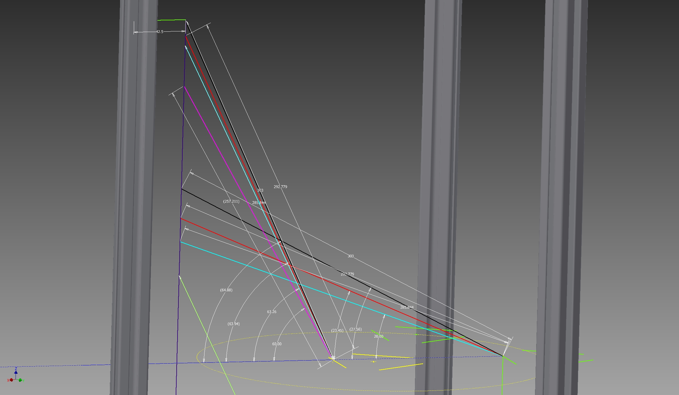
Thank you ybanrab, perhaps this picture can illustrate it better, I follow some of the posts to calculate different lengths of the rods in the picture you can see them as pairs of what angle they would have homed and at the edge of the bed, I am leaning towards the red pair since I am getting 63.94 and 23.45 respectively it seems the better solution, am I right?
Or should I go with cyan 63.26 and 20?
Edited 2 time(s). Last edit at 10/12/2014 06:10PM by plastik.
Or should I go with cyan 63.26 and 20?
Edited 2 time(s). Last edit at 10/12/2014 06:10PM by plastik.
|
Re: Arm length calculation help on own-design delta needed October 12, 2014 08:47PM |
Registered: 10 years ago Posts: 240 |
Using 60 degrees is absolutely pointless. Tell me ANY time where that measurement actually matters to the printer.
The only time it hits 60 degrees is at top, in the resting position. It has no bearing on how wide or tall you can print (other than getting in your way). It's a static measurement on a measurement that matters only when moving.
Make sure your rods can reach the edge of your build surface and ignore the angle. If you need more height, add more to your vertical rails. Taking it out of your diagonals is just silly.
As for how much extra, Cyan should be fine.
|
Re: Arm length calculation help on own-design delta needed October 12, 2014 09:25PM |
Registered: 10 years ago Posts: 240 |
Quote
hercek
I'm not sure this is true. At the location most far away of a tower, the arm of that tower will have small angle to bed (in ybanrab situation about 24° which is not that small anyway). But the arms to the other too towers will have quite big angle to the bed (about 63°), those arms should take the most of the probing force (which is in the Z axe direction). Maybe this situation may be bad when the pairs of arms going to the same tower are too near to each other, but hopefully all people realize that the distance between arm pair should be as big as possible (within the design constrains of the effector platform).Quote
sheepdog43
Also, if you plan to auto level or auto calibrate, just reaching the edge of the build plate is not enough. The further out you go, the more flat one arm will be, leaving you little to no leverage to depress the probe. Even if you do have a little extra, I recommended not probing more than 75-80% from the center of the build platform to reduce wear and tear as it is VERY hard on your diagonals doing this.
An original rostock here does not have problems probing about 80% away from centre.
All three sets of arms are needed to hold an effector in place horizontally. If one set of arms is horizontal, they are no longer holding the effector flat and the effector can rock. It doesn't take much to throw off calibration. Yes, two sets are holding it down, but we have three sets for a reason. Take off a set of arms and you will see where the problem is.
When you calibrated your printer, remember how the print was bowl shaped? It's not linear, the further out you go, the worse the bowl shape gets.Quote
hercek
I do not understand why bigger printer would need bigger accuracy of parts barring the problems of frame/rod elasticity (probably what you mean by deflection).
So lets say your Kossel diagonal is accurate to within 0.04mm giving you great precision. However, in reality, you probably aren't perfectly flat. There can still be 0.01mm bowl shape in your print, you just can't spot it and it's irrelevant.
That 0.01mm bowl shape at 170mm wide balloons up to 10mm by the time you reach 500mm wide. You need to dial down to something like .0015 diagonal accuracy just to get a .01mm accuracy across the bed at 500mm.
|
Re: Arm length calculation help on own-design delta needed October 13, 2014 01:03AM |
Registered: 9 years ago Posts: 25 |
|
Re: Arm length calculation help on own-design delta needed October 13, 2014 05:33AM |
Registered: 10 years ago Posts: 732 |
The angles change with changing printer delta radius and diagonal rod length.Quote
plastik
What angle should the rods have when the nozzle is all the way to the edge of the printing bed? Is it 20 degrees?
Do not try to measure them. It is hard to do it precisely. It is easier to measure distances.
The only thing why you need them is to get ball joints with enough free angular movement.
When delta
* around ball joint axe is 0 .. 90°
* in the direction perpendicular to it, it is -30° .. +30°
In most cases, the diagonal rod is a bit longer than delta
Edited 1 time(s). Last edit at 10/14/2014 01:37PM by hercek.
|
Re: Arm length calculation help on own-design delta needed October 13, 2014 06:25AM |
Registered: 10 years ago Posts: 732 |
In such a position, the horizontal pair does not need to prevent rotation in the horizontal axe perpendicular to it (other two arm pairs will do it just fine). The horizontal pair still needs to prevent rotation along vertical axe (which would lead to smaller platform tilting too). Maybe you are right and these positions are significantly worse even when arm pair distance is big enough but I have doubts without proper momentum propagation analyses.Quote
sheepdog43
Quote
hercek
I'm not sure this is true. At the location most far away of a tower, the arm of that tower will have small angle to bed (in ybanrab situation about 24° which is not that small anyway). But the arms to the other too towers will have quite big angle to the bed (about 63°), those arms should take the most of the probing force (which is in the Z axe direction). Maybe this situation may be bad when the pairs of arms going to the same tower are too near to each other, but hopefully all people realize that the distance between arm pair should be as big as possible (within the design constrains of the effector platform).Quote
sheepdog43
Also, if you plan to auto level or auto calibrate, just reaching the edge of the build plate is not enough. The further out you go, the more flat one arm will be, leaving you little to no leverage to depress the probe. Even if you do have a little extra, I recommended not probing more than 75-80% from the center of the build platform to reduce wear and tear as it is VERY hard on your diagonals doing this.
An original rostock here does not have problems probing about 80% away from centre.
All three sets of arms are needed to hold an effector in place horizontally. If one set of arms is horizontal, they are no longer holding the effector flat and the effector can rock. It doesn't take much to throw off calibration. Yes, two sets are holding it down, but we have three sets for a reason. Take off a set of arms and you will see where the problem is.
Here we claim essentially the same thing. Non linearity causes the errors to be bigger at the heat bed edges. But we are looking at it from different angles:Quote
sheepdog43
When you calibrated your printer, remember how the print was bowl shaped? It's not linear, the further out you go, the worse the bowl shape gets.Quote
hercek
I do not understand why bigger printer would need bigger accuracy of parts barring the problems of frame/rod elasticity (probably what you mean by deflection).
So lets say your Kossel diagonal is accurate to within 0.04mm giving you great precision. However, in reality, you probably aren't perfectly flat. There can still be 0.01mm bowl shape in your print, you just can't spot it and it's irrelevant.
That 0.01mm bowl shape at 170mm wide balloons up to 10mm by the time you reach 500mm wide. You need to dial down to something like .0015 diagonal accuracy just to get a .01mm accuracy across the bed at 500mm.
* you say this is bad because small calibration errors lead to big effector errors at bed edges;
* I say this is good because the small calibration errors can be detected at the edges (and thanks to that we can correct them).
Btw, I did not have bowl problem at the beginning. I had a serious tower position problem which leads to a different error shape. Anyway diagonal rod and tower position errors can be easily fixed with a zprobe (measuring just below the head) and the math in this notebook [github.com]
The comments in it are a bit obsolete (e.g. it is known now that it converges nicely if at least 8 calibration points are used). But it allows to calibrate as precisely as micro-step length and printer play (slop) allow with both marlin and repetier. I'll update it sometimes. To get good results, one needs to probe points when one arm pair is almost horizontal (where the errors are biggest thanks to the non linearity).
|
Re: Arm length calculation help on own-design delta needed October 13, 2014 05:49PM |
Registered: 9 years ago Posts: 25 |
|
Re: Arm length calculation help on own-design delta needed October 14, 2014 07:31AM |
Registered: 10 years ago Posts: 240 |
Quote
hercek
In such a position, the horizontal pair does not need to prevent rotation in the horizontal axe perpendicular to it (other two arm pairs will do it just fine). The horizontal pair still needs to prevent rotation along vertical axe (which would lead to smaller platform tilting too). Maybe you are right and these positions are significantly worse even when arm pair distance is big enough but I have doubts without proper momentum propagation analyses.
It's not really an issue when printing, the problem is when you are trying to push the effector down and activate a switch. You have no leverage on that one side of the effector allowing it to rock and no, the others do not compensate. I was getting about 3mm deviation because of it.
The worst part though, was that you just lost 1/3rd of your load bearing pivots, and the other take all the abuse. After a few hundred iterations my ball joints were junk.
You are right, it's good because you get a heck of a level build plane, I get fantastic prints from it, I hadn't really thought of that.Quote
sheepdog43
* you say this is bad because small calibration errors lead to big effector errors at bed edges;
* I say this is good because the small calibration errors can be detected at the edges (and thanks to that we can correct them).
However, it takes a lot more effort to get there.
In Rich Cattel firmware I had to run the calibration it in stages or it would never have calibrated.
|
Re: Arm length calculation help on own-design delta needed October 14, 2014 01:31PM |
Registered: 10 years ago Posts: 732 |
Quote
sheepdog43
The worst part though, was that you just lost 1/3rd of your load bearing pivots, and the other take all the abuse. After a few hundred iterations my ball joints were junk.
I do not have problems with that. I always probed a point 5 times. The differences were almost always at most ±1 micro-step regardless of position. I have got about two measurements at tower A base which were ±2 micro-steps. I'm not sure why. Other tens of measurements there were ok. I probed each bed edge at least 50 times and did not notice ball joint degradation. Either MP-Jet joints are so good or 50 is still too small. But it is important to place two rods linking to one tower far away from each other.
I did not ever used Rich's firmware. He implemented manual calibration rules in sw. I'm not surprised it does not always converge well. Now, when Dejay has shown the error function minimization converges well, we just need to wait till somebody implements this (i.e. the method in the maxima notebook) in a completely automated way and we will calibrate in one iteration.
|
Re: Arm length calculation help on own-design delta needed February 19, 2015 06:42PM |
Registered: 10 years ago Posts: 14,672 |
In RepRapFirmware, the auto-calibration routine I wrote determines the endstop adjustments and delta radius using 4 probe points (one in front of each tower and one in the centre). So it assumes that the towers form an equilateral triangle. I tried to make the adjustment formula sufficiently precise mathematically so as to converge very quickly. In practice, it converges to within 0.02mm after 2 iterations provided the delta radius is not a long way off to to begin with.
I'm interested in in correcting for inaccuracies in the tower positions too, so I'll take a closer look at the wxMaxima calculations. However, I'm wondering whether inaccuracies in the tower positions really are a more significant source of error than the towers being not perpendicular to the bed, or twisted, or the diagonal rods being slightly different lengths. Does anybody know?
Large delta printer [miscsolutions.wordpress.com], E3D tool changer, Robotdigg SCARA printer, Crane Quad and Ormerod
Disclosure: I design Duet electronics and work on RepRapFirmware, [duet3d.com].
|
Re: Arm length calculation help on own-design delta needed February 20, 2015 02:01PM |
Registered: 10 years ago Posts: 732 |
Quote
dc42
However, I'm wondering whether inaccuracies in the tower positions really are a more significant source of error than the towers being not perpendicular to the bed, or twisted, or the diagonal rods being slightly different lengths. Does anybody know?
I think it will depend on the type of printer. Traditional Rostock will probably only have bad tower positions and possibly (not probable) twisted/tilted the whole frame. The point is that when building Rostock, you drill top and bottom plate at once. So the tower positions on top and bottom are the same. If you build a Kossel then you can compare that all your top/bottom extrusions are exactly the same length so assuming the triangle is equilateral makes sense.
|
Re: Arm length calculation help on own-design delta needed January 06, 2016 04:03AM |
Registered: 12 years ago Posts: 300 |
I'm wondering: does this design reduce the non-linearity, and so simplify the tuning?
[www.festo.com]
Frédéric
[www.festo.com]
Frédéric
|
Re: Arm length calculation help on own-design delta needed January 06, 2016 04:32AM |
Registered: 10 years ago Posts: 14,672 |
Quote
fma
I'm wondering: does this design reduce the non-linearity, and so simplify the tuning?
[www.festo.com]
The post you replied to is more than 10 months old. Things have moved on. I implemented least squares auto delta calibration in RepRapFirmware, of up to 7 factors, so the tower positions are now auto calibrated as well. My thanks to hercek, whose wxMaxima script gave me the inspiration to do this.
The errors that can't be calibrated out so easily come from build inaccuracies. For example, the diagonal rods lengths may be slightly different, or the bearing spacing at the top and bottom of a pair of rods might not be quite equal. These errors cause the effector to tilt as it translates in the XY plane.
One possible advantage of the configuration that you illustrate is that it avoids the problem of towers not being perpendicular to the bed. Against that, the moving mass appears to be much greater.
Edited 1 time(s). Last edit at 01/06/2016 06:37PM by dc42.
Large delta printer [miscsolutions.wordpress.com], E3D tool changer, Robotdigg SCARA printer, Crane Quad and Ormerod
Disclosure: I design Duet electronics and work on RepRapFirmware, [duet3d.com].
|
Re: Arm length calculation help on own-design delta needed January 06, 2016 04:50AM |
Registered: 12 years ago Posts: 300 |
|
Re: Arm length calculation help on own-design delta needed January 06, 2016 01:32PM |
Registered: 10 years ago Posts: 732 |
No. It does not help in any significant way compared to a simple linear delta. I would say it's complexity will be about the same but worst, I do not know about any prepared tools (like e.g. dc42 calibration web page or his firmware) which would help you.Quote
fma
I'm wondering: does this design reduce the non-linearity, and so simplify the tuning?
[www.festo.com]
If you want simple calibration go cartesian. CoreXY is a nice design. If you want speed go delta. If you like the funny way delta moves go delta too

As dc42 indicated, delta calibration is easier now than it was before but for a delta calibration to be really easy somebody needs to derive and publish a calibration procedure for tilted towers.
|
Re: Arm length calculation help on own-design delta needed January 06, 2016 03:17PM |
Registered: 12 years ago Posts: 300 |

Sorry, only registered users may post in this forum.