Kossel Mini flatness calibration
Posted by M4vrick99
|
Kossel Mini flatness calibration February 28, 2015 08:27AM |
Registered: 9 years ago Posts: 7 |
Hi all 
I have some troubles calibrating my new Kossel Mini.
The issue is not easy to explain, but easy to see.
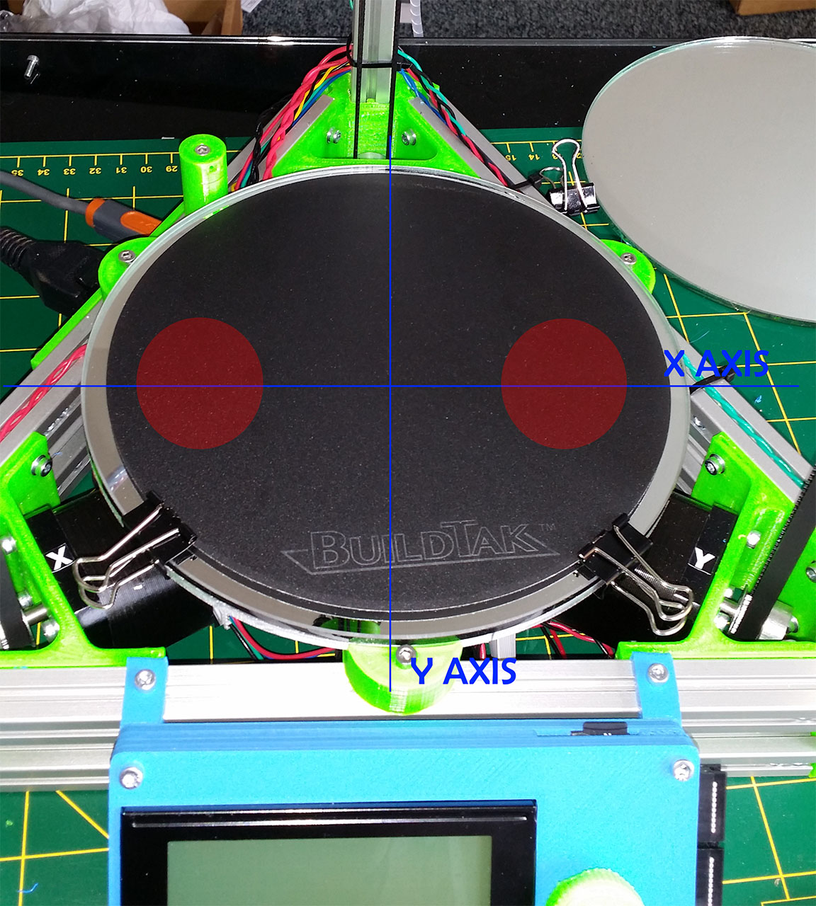
If I print a ring centered on the bed the first layer is more far from the bed on the X axis ends than all the other parts, and only on the X axis.
I guess the smooth_rod_offset is good because the issue is only affecting the X axis, the hotend is printing the same way on the center and on the Y axis.
Attached is a pic of my bed with axis and the two reds cercles are where the printing is over the bed (approx, not exact spot). I say over the bed because when watching the first layer I can clearly see the hotend printing on the air.
i've check the flatness of the mirror with a straight metal ruler in every direction and it's as flat as I can see.
I've done several calibration but the issue is not relating to the towers.
Is there a way to adjust hotend displacement only over one axis ? is there any mecanicam issue which could lead to this kind of print ?
Thank you
Edited 1 time(s). Last edit at 02/28/2015 08:29AM by M4vrick99.
I have some troubles calibrating my new Kossel Mini.
The issue is not easy to explain, but easy to see.
If I print a ring centered on the bed the first layer is more far from the bed on the X axis ends than all the other parts, and only on the X axis.
I guess the smooth_rod_offset is good because the issue is only affecting the X axis, the hotend is printing the same way on the center and on the Y axis.
Attached is a pic of my bed with axis and the two reds cercles are where the printing is over the bed (approx, not exact spot). I say over the bed because when watching the first layer I can clearly see the hotend printing on the air.
i've check the flatness of the mirror with a straight metal ruler in every direction and it's as flat as I can see.
I've done several calibration but the issue is not relating to the towers.
Is there a way to adjust hotend displacement only over one axis ? is there any mecanicam issue which could lead to this kind of print ?
Thank you
Edited 1 time(s). Last edit at 02/28/2015 08:29AM by M4vrick99.
|
Re: Kossel Mini flatness calibration February 28, 2015 09:42AM |
Registered: 10 years ago Posts: 14,672 |
I have a similar issue. I think it is because on my build, the bed is not quite perpendicular to the towers, which I can see using a carpenter's square. At this stage, I have a couple of possibilities:
1. Try to make them perpendicular, either by adjusting the frame or by filing down the bed supports. I have made some progress on this already - I found that the bed was not at quite the same height above the aluminium extrusions on the 3 sides due to variations in the printed parts, and I have filed the bed support part surfaces to make it flatter.
2. Do a mathematical analysis of the effect of the bed not being perpendicular to the towers, and compensate for it in the firmware, including an auto-calibration mechanism.
I notice that Think3DPrint3D have changed the heated bed mounting on their newer Mini Kossel kits. It no longer uses printed bed supports, instead it uses a slightly larger bed plate that attaches to the extrusions via steel standoff pillars.
Large delta printer [miscsolutions.wordpress.com], E3D tool changer, Robotdigg SCARA printer, Crane Quad and Ormerod
Disclosure: I design Duet electronics and work on RepRapFirmware, [duet3d.com].
|
Re: Kossel Mini flatness calibration February 28, 2015 10:02AM |
Registered: 9 years ago Posts: 7 |
your idea sounds great.
I've seen the think3dprint3D upgrade, My printer is one of the last before this new version
I guess I can try to unscrew the heated bed a little more to move it up on one side.
But the gap is on the both side of the X axis, if it's an perpendicular problem there is one side too high and one too low, not too low and each side and good at the center.
|
Re: Kossel Mini flatness calibration February 28, 2015 10:13AM |
Registered: 10 years ago Posts: 14,672 |
Quote
M4vrick99
But the gap is on the both side of the X axis, if it's an perpendicular problem there is one side too high and one too low, not too low and each side and good at the center.
It's more complicated than that. You've done delta calibration, so the endstops and delta radius are adjusted to get equal nozzle heights in front of each tower and at the centre. If the towers were positioned at the corners of an equilateral triangle, perpendicular to the bed, and not twisted, then this would ensure a uniform printing height across the whole bed. But if any of those assumptions is not true, then the printing plane will not be flat and you will get height errors, in particular at places far from where the calibration was done (i.e. near the edges of the bed between pairs of towers).
btw if you are using the Z probe to do auto calibration, then I have found that the first time I do a Z probe after the probe is deployed, the trigger height is around 0.1mm different from the trigger height for subsequent probes. This was responsible for part of the error I was getting. I have now changed the auto calibration macro file I am using to do an extra probe at the start of the sequence and throw away the result.
Large delta printer [miscsolutions.wordpress.com], E3D tool changer, Robotdigg SCARA printer, Crane Quad and Ormerod
Disclosure: I design Duet electronics and work on RepRapFirmware, [duet3d.com].
|
Re: Kossel Mini flatness calibration February 28, 2015 10:31AM |
Registered: 9 years ago Posts: 7 |
|
Re: Kossel Mini flatness calibration February 28, 2015 06:47PM |
Registered: 9 years ago Posts: 7 |
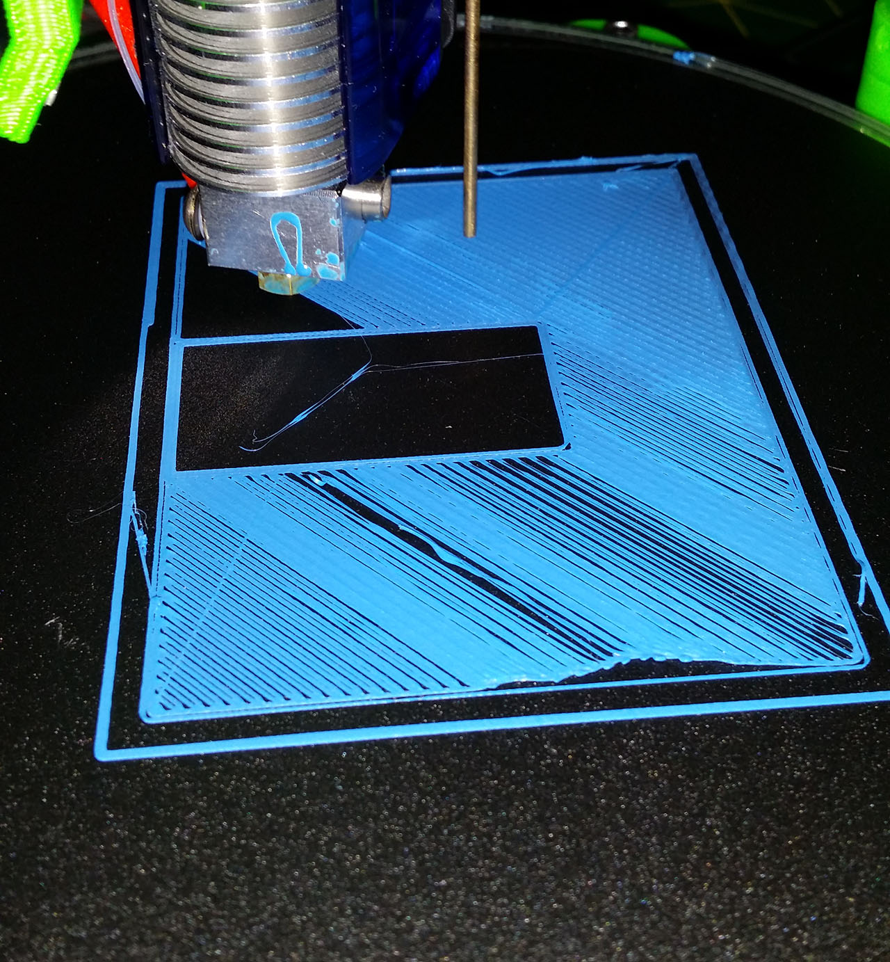
A view of the issue
At the top of the image it's mainly good, at the bottom of the image is the spot where the printhead is above the bed.
The object is centered on the bed, looks like your idea is good dc42, the bed is not perpendicular to the towers.
At the top of the image it's mainly good, at the bottom of the image is the spot where the printhead is above the bed.
The object is centered on the bed, looks like your idea is good dc42, the bed is not perpendicular to the towers.
|
Re: Kossel Mini flatness calibration March 11, 2015 01:30AM |
Registered: 9 years ago Posts: 83 |
Hi M4vrick99
I am having a similar issue with my mini kossel that i recently just built. I manually calibrate due to issues with my auto leveling probe snagging and dragging on the print bed. I just cannot seem to get my bed level then it throws off larger prints just like in your picture...My kit was also from think3dprint3d before the upgrade.... have you found a reasonable solution or does finding a larger printbed that fits directly to the extrusions seem to be the only way?
One possible solution other than filing the printed part perfect, i was thinking was to drill holes for screws on the printed bed holders (next to the one in the middle already) then using metal arms to hold the printbed down and springs around the screws. You could tighten these new screws (with the springs) to sorta level the bed mechanically.... however there might be better solutions? Let me know what you think.
|
Re: Kossel Mini flatness calibration March 11, 2015 08:51AM |
Registered: 9 years ago Posts: 189 |
At the moment my Mini Kossel prints parts around 0.05 mm accuracy.
I manually performed calibrations.
I have a similar problem that I need to fix. Auto level probing can't handle tilted or whatever print bed.
Upper left side of print bed (Negative X and positive Y coordinates) has little higher than the rest area.
It causes the immature first layer problem for large print part.
I've spent last two days playing with Marlin RichCattell v1.0.4 that has M666 and auto calibration but
it doesn't look promising. The auto calibration has maximum iteration of 100.
Once it reaches, it produces success message and makes the board freeze.
When I set the bed diameter to 140 mm (previous bed size was 170 mm) thinking small print bed would
get rid of titled effect but it made even worse - center of bed and Z height calibration didn't go through.
There was always 3 mm off height difference between the three towers. Or If all the three towers are
leveled, the center of bed was 3 mm over the print bed (Z:0).
Increasing the Delta radius by M666 R### up to 150 wouldn't lower the hotend 0.1 mm.
I came into conclusion that there must be written code that controls printable bed diameter given by DEFAULT_DELTA_DIAGONAL_ROD.
Maybe I'm wrong.
I manually performed calibrations.
I have a similar problem that I need to fix. Auto level probing can't handle tilted or whatever print bed.
Upper left side of print bed (Negative X and positive Y coordinates) has little higher than the rest area.
It causes the immature first layer problem for large print part.


I've spent last two days playing with Marlin RichCattell v1.0.4 that has M666 and auto calibration but
it doesn't look promising. The auto calibration has maximum iteration of 100.
Once it reaches, it produces success message and makes the board freeze.
When I set the bed diameter to 140 mm (previous bed size was 170 mm) thinking small print bed would
get rid of titled effect but it made even worse - center of bed and Z height calibration didn't go through.
There was always 3 mm off height difference between the three towers. Or If all the three towers are
leveled, the center of bed was 3 mm over the print bed (Z:0).
// Center-to-center distance of the holes in the diagonal push rods.
#define DEFAULT_DELTA_DIAGONAL_ROD 215.0 // (217.5) mm

// Horizontal offset from middle of printer to smooth rod center.
#define DELTA_SMOOTH_ROD_OFFSET 147.0 // mm //158

// Horizontal offset of the universal joints on the end effector.
// E3D V6 Hotend effector
#define DELTA_EFFECTOR_OFFSET 30.0 // mm (20.0 for J-Head)

// Horizontal offset of the universal joints on the carriages.
#define DELTA_CARRIAGE_OFFSET 19.0 // mm

// Effective horizontal distance bridged by diagonal push rods.
// 98.0 (147.0 - 30.0 - 19.0)
#define DEFAULT_DELTA_RADIUS (DELTA_SMOOTH_ROD_OFFSET-DELTA_EFFECTOR_OFFSET-DELTA_CARRIAGE_OFFSET)
Increasing the Delta radius by M666 R### up to 150 wouldn't lower the hotend 0.1 mm.
I came into conclusion that there must be written code that controls printable bed diameter given by DEFAULT_DELTA_DIAGONAL_ROD.
Maybe I'm wrong.
|
Re: Kossel Mini flatness calibration March 11, 2015 09:31AM |
Registered: 10 years ago Posts: 14,672 |
On my list of things to do is a thorough mathematical analysis of the effect of a tilted frame or tilted bed, and the effect of the 3 towers not quite forming an equilateral triangle. My aim is to develop a 7 or greater point probing routine that not only gets the height correct at the centre and in front of each f the towers, but at the edges of the bed midway between the towers too.
My suggestion for now is that if after doing delta calibration, the head is too low at a point midway between a pair of towers, then adjust the configured XY coordinates of the opposite tower to specify that it is a little further away from the centre than the other two towers. Then re-run delta calibration.
Large delta printer [miscsolutions.wordpress.com], E3D tool changer, Robotdigg SCARA printer, Crane Quad and Ormerod
Disclosure: I design Duet electronics and work on RepRapFirmware, [duet3d.com].
|
Re: Kossel Mini flatness calibration March 12, 2015 01:27PM |
Registered: 10 years ago Posts: 732 |
Sorry, I did not read this thread.
But if you still do not have it calibrated (probably because simple calibration tutorials did not work) then:
But if you still do not have it calibrated (probably because simple calibration tutorials did not work) then:
- If you suck at math: Try to read comments in this file: [github.com]
- If you are good at math: Actually execute the file in maxima (you will need a z-probe and you may need my branch of marlin for that). The file will give you the right calibration parameters if your towers are not tilted, the machine does not have an unwanted play, and you provided at least 8 probing points.
|
Re: Kossel Mini flatness calibration March 12, 2015 10:55PM |
Registered: 9 years ago Posts: 189 |
Long story to short, I probably (?) found the tilted bed problem. I was looking for wrong place.
I thought electrical tape would secure the joint in case it gets loose but the joint developed hard-to-see freeplay around 1.0 mm.
I found it last night after replacement of the aluminium bed with 5mm thickness of round glass. The Z height were keep shifting from 0.1 mm to 2.0 mm.
The loose joints of four diagonal rods caused the tilted bed apparently. Misaligned / different length of rod makes the nozzle tip tilts, changes physical Z height when it moves on bed surface.
Three cases of bed level
Each time I did calibration it changes the level of print bed which made calibration impossible.
1st calibration data
2nd calibration data
3rd calibration data
Above bed graphs were generated by below Octave script.
I manually probed 37 grid points using G30 and text editor to make the data file that the octave script reads.
Manual calibration of bed level steps I learned so far.
Set the base line - lower all three carriages equal distance from the physical endstops.
Example: M666 X-5.0 Y-5.0 Z-5.0
Set Z height - M666 H210.03
Set X/Y/Z height in order
M666 X-#.##
M666 y-#.##
M666 z-#.##
Check Z height again
If Z height becomes bigger than previous value, i.e. -0.2, increase the Delta Radius .5 to 1.00.
If Z height becomes smaller than previous value,i.e. 0.2, decrease the Delta Radius .5 to 1.00.
(I expected changing the Delta Radius followed by homing would change the Z height wouldn't work.)
Set X/Y/Z height in order
Repeat this procedure until the center of bed, three axis points are at the same level (Z:0.00).
@hercek
Thanks.
I measured three points on each side of the base frame.
XY side: 60.25, 60.15, 60.25
YZ side: 60.00, 60.10, 60.00
ZX side: 60.20, 60.15, 60.00
Distance of three vertical extrusion was pretty equal to 285mm.
All the calibration documents I've read through assume the physical dimension is right.
And they explain how to calibrate the uneven bed level.
The mysterious thing is they don't explain the range of acceptable level difference by auto level probe.
In my case, the Z height difference is 1.0 mm in worst case across the bed.
Suppose the auto level probe handles variation of Z height up to 1.5 mm, I wouldn't notice it until
the titled effector lowers the Z height eventually.
Edited 1 time(s). Last edit at 03/12/2015 11:09PM by janpenguin.
I thought electrical tape would secure the joint in case it gets loose but the joint developed hard-to-see freeplay around 1.0 mm.
I found it last night after replacement of the aluminium bed with 5mm thickness of round glass. The Z height were keep shifting from 0.1 mm to 2.0 mm.
The loose joints of four diagonal rods caused the tilted bed apparently. Misaligned / different length of rod makes the nozzle tip tilts, changes physical Z height when it moves on bed surface.


Three cases of bed level
Each time I did calibration it changes the level of print bed which made calibration impossible.
1st calibration data

2nd calibration data

3rd calibration data

Above bed graphs were generated by below Octave script.
Source

[boim.com]

# octave script
#
# Current Delta geometry values:
# X (Endstop Adj): -8.29
# Y (Endstop Adj): -7.19
# Z (Endstop Adj): -11.97
# P (Z-Probe Offset): X23.00 Y-9.00 Z-5.60
# A (Tower A Position Correction): 0.00
# B (Tower B Position Correction): 0.00
# C (Tower C Position Correction): 0.00
# I (Tower A Radius Correction): 0.00
# J (Tower B Radius Correction): 0.00
# K (Tower C Radius Correction): 0.00
# R (Delta Radius): 111.80
# D (Diagonal Rod Length): 215.00
# H (Z-Height): 211.70

# probe4.dat
bed = dlmread('probe4.dat', ",");
bed(:,3) = -bed(:,3);

DP.RodLen = 215.0;
DP.RADIUS = 111.80;
more off
[deltaErr,towerErr] = guessDeltaErr(DP,bed)

#{
-1.09586 0.72471 1.25052 1.80807

nEval = 87
status = 0
err = 0.010827
c =

6.0341e-01
3.0065e-03
5.4365e-03
-8.3239e-06
5.1835e-05
6.7661e-05

deltaErr = -1.0959
towerErr =

-0.72471 -1.25052 -1.80807
#}
I manually probed 37 grid points using G30 and text editor to make the data file that the octave script reads.
20.00,60.00, -1.200
0.00,60.00, -1.29
-20.00, 60.00, -1.29
-40.00, 40.00, -1.06
-20.00, 40.00, -0.99
0.00, 40.00, -0.87
...
Manual calibration of bed level steps I learned so far.
Set the base line - lower all three carriages equal distance from the physical endstops.
Example: M666 X-5.0 Y-5.0 Z-5.0
Set Z height - M666 H210.03
Set X/Y/Z height in order
M666 X-#.##
M666 y-#.##
M666 z-#.##
Check Z height again
If Z height becomes bigger than previous value, i.e. -0.2, increase the Delta Radius .5 to 1.00.
If Z height becomes smaller than previous value,i.e. 0.2, decrease the Delta Radius .5 to 1.00.
(I expected changing the Delta Radius followed by homing would change the Z height wouldn't work.)
Set X/Y/Z height in order
Repeat this procedure until the center of bed, three axis points are at the same level (Z:0.00).
@hercek
Thanks.
I measured three points on each side of the base frame.
XY side: 60.25, 60.15, 60.25
YZ side: 60.00, 60.10, 60.00
ZX side: 60.20, 60.15, 60.00
Distance of three vertical extrusion was pretty equal to 285mm.
All the calibration documents I've read through assume the physical dimension is right.
And they explain how to calibrate the uneven bed level.
The mysterious thing is they don't explain the range of acceptable level difference by auto level probe.
In my case, the Z height difference is 1.0 mm in worst case across the bed.
Suppose the auto level probe handles variation of Z height up to 1.5 mm, I wouldn't notice it until
the titled effector lowers the Z height eventually.
Edited 1 time(s). Last edit at 03/12/2015 11:09PM by janpenguin.
|
Re: Kossel Mini flatness calibration March 12, 2015 11:18PM |
Registered: 9 years ago Posts: 189 |
Quote
https://github.com/hercek/Marlin/blob/Marlin_v1/calibration.wxm
/* [wxMaxima: comment start ]
This document helps to find proper values for these firmware parameters: tower positions, diagonal rod length,
and top endstop position offsets. Errors in these firmware parameters can be fixed perfectly provided the
assumptions bellow are valid.
* We assume that the towers are parallel. Ensuring that the towers are parallel is tricky. Drill both top and
bottom plates at once. This ensures top and bottom tower positions are exactly the same. That is the easy
part. Then do not twist top plate with respect to the bottom one. They are not twisted if diagonals have the
same length.
* We assume that all your diagonal rods have the same length (although the common length is not known
precisely). You can easily achieve this with a jig. (Note: If your diagonal rods do not have the same length it will
introduce rotations to your platform. These will not have that big impact on z-height but will have significant
impact on x/y precision.)
* We assume that the bed is perpendicular to the towers. Making sure the bed is perpendicular is harder but
callibration can partially fix it with the top endstop adjustements. This compensation will not be perfect. For
example, if your bed is 1 mm higer on one side (compared to the other side) then this will lead to errors smaller
than about 0.3 mm, possibly much smaller. I did not investigate this in details. This compensation using top
endstops will also lead to your prints being as skewed as your bed is.
* We assume no other auto level is active (e.g. Johann's auto leveling cannot be enabled).
[wxMaxima: comment end ] */
I'll write about how to identify physical misalignment of frame parts.
|
Re: Kossel Mini flatness calibration March 13, 2015 04:58AM |
Registered: 10 years ago Posts: 732 |
I do not use Johann's (interpolation based) auto levelling. So I do not know what it can handle. It is not needed if the printer is calibrated well.
You need your bed levelled to at least 0.1 mm more likely something like 0.05 mm if you want the first layer to stick well. If your printer is really well built then it is possible to calibrated down to about 0.025 mm.
You need your bed levelled to at least 0.1 mm more likely something like 0.05 mm if you want the first layer to stick well. If your printer is really well built then it is possible to calibrated down to about 0.025 mm.
|
Re: Kossel Mini flatness calibration March 29, 2015 08:27PM |
Registered: 9 years ago Posts: 189 |
I manually sanded an aluminium plate to make it as print bed. And before I installed it, I measured the surface using 0.04mm thickness of blade and an engineering square.
There was no spot that takes the 0.04 mm blade.
I did manual calibration within 15 minutes.
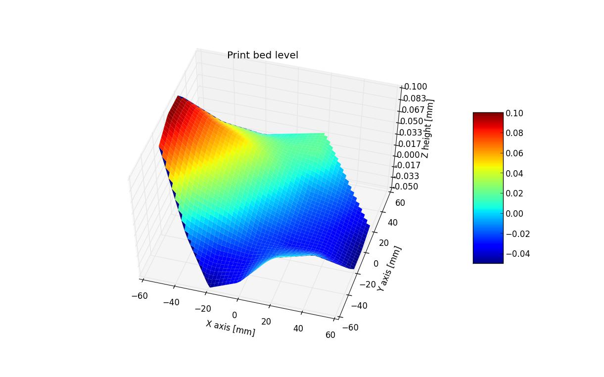
I ran G29 Auto level probe twice. Here is one of the results.
Text data file I made from G29 output.
Python source code I made to plot 3D surface of print bed. It reads the text data file and draws 3D grape.
There was no spot that takes the 0.04 mm blade.

I did manual calibration within 15 minutes.
>>> M666 L
SENDING:M666 L
Current Delta geometry values:
X (Endstop Adj): -5.40
Y (Endstop Adj): -5.05
Z (Endstop Adj): -4.95
P (Z-Probe Offset): X10.95 Y-4.30 Z-5.80
A (Tower A Position Correction): 0.00
B (Tower B Position Correction): 0.00
C (Tower C Position Correction): 0.00
I (Tower A Radius Correction): 0.00
J (Tower B Radius Correction): 0.00
K (Tower C Radius Correction): 0.00
R (Delta Radius): 111.50
D (Diagonal Rod Length): 214.86
H (Z-Height): 211.60
I ran G29 Auto level probe twice. Here is one of the results.
Text data file I made from G29 output.
20.00,60.00, -0.290
0.00,60.00, -0.270
-20.00, 60.00, -0.330
-40.00, 40.00, -0.150
-20.00, 40.00, -0.180
0.00, 40.00, -0.170
20.00, 40.00, -0.170
40.00, 40.00, 0.040
60.00, 20.00, 0.020
40.00, 20.00, -0.020
20.00, 20.00, -0.050
0.00, 20.00,-0.080
-20.00, 20.00, -0.140
-40.00, 20.00, -0.170
-60.00, 20.00, 0.150
-60.00, 0.00, 0.110
-40.00, 0.00, 0.060
-20.00, 0.00, -0.020
0.00, 0.00, -0.090
20.00, 0.00, -0.150
40.00, 0.00, -0.170
60.00, 0.00, 0.330
60.00, -20.00, 0.260
40.00, -20.00, 0.200
20.00, -20.00, 0.120
0.00, -20.00, 0.020
-20.00, -20.00, -0.050
-40.00, -20.00, -0.150
-60.00, -20.00, 0.300
-40.00, -40.00, 0.210
-20.00, -40.00, 0.150
0.00, -40.00, 0.040
20.00, -40.00, -0.070
40.00, -40.00, 0.260
20.00, -60.00, 0.260
0.00, -60.00, 0.210
-20.00, -60.00, 0.110

Python source code I made to plot 3D surface of print bed. It reads the text data file and draws 3D grape.
# [stackoverflow.com]

from mpl_toolkits.mplot3d import Axes3D
from matplotlib.mlab import griddata
from matplotlib import cm
from matplotlib.ticker import LinearLocator, FormatStrFormatter
import matplotlib.pyplot as plt
import numpy as np
import sys


def xyz_ret(file):
    import codecs
    f = open(file, 'r')
    xyz = []
    for line in f:
        if line.startswith(codecs.BOM_UTF8):
            line = line[3:]
        ret = line.replace('\n','')
        xyz.append(map(float,(ret.split(','))))
        # xyz.append(map(float,(ret.split('\t'))))
    xyz = np.array(xyz)
    return xyz[:,0],xyz[:,1],xyz[:,2]

# lp_0325_1.dat
x,y,z = xyz_ret('lp_0325_1.dat')

fig = plt.figure()
# ax = fig.add_subplot(111, projection='3d')
ax = fig.gca(projection='3d')

xi = np.linspace(min(x), max(x))
yi = np.linspace(min(y), max(y))
X, Y = np.meshgrid(xi, yi)
Z = griddata(x, y, z, xi, yi)

surf = ax.plot_surface(X, Y, Z, rstride=1, cstride=1, cmap=cm.jet,
        linewidth=0, antialiased=True, vmin=min(z), vmax=max(z))

ax.set_xlim(min(x), max(x))
ax.set_ylim(min(y), max(y))
ax.set_zlim(min(z), max(z))

ax.set_title('Print bed level')
ax.set_xlabel('X axis [mm]')
ax.set_ylabel('Y axis [mm]')
ax.set_zlabel('Z height [mm]')
ax.zaxis.set_major_locator(LinearLocator(10))
ax.zaxis.set_major_formatter(FormatStrFormatter('%.03f'))
fig.colorbar(surf, shrink=0.5, aspect=5)

# ax.set_zlim3d(min(z), max(z))

# ax.w_zaxis.set_major_locator(LinearLocator(10)):
# ax.w_zaxis.set_major_formatter(FormatStrFormatter('%.03f'))

# fig.colorbar(surf, shrink=0.5, aspect=5)
# fig.colorbar(surf)

plt.show()
|
Re: Kossel Mini flatness calibration March 29, 2015 09:47PM |
Registered: 9 years ago Posts: 977 |
|
Re: Kossel Mini flatness calibration March 31, 2015 07:37AM |
Registered: 9 years ago Posts: 189 |
@AndrewBCN
Thanks!
I finally nailed the print bed calibration early in the morning today.
After manual calibration using M666, I attempted the auto calibration of RichCattell version of Marlin.
During the calibration I found the pulley of X axis' stepper motor was loose. It turned out the pulley was slightly moving back and forth which makes exact calibration is impossible. And then the second trial of auto calibration finished in seventh iteration.
In summary, to get the calibration done, the Delta 3D Printer needs to be mechanically sounding.
All six diagonal length should be exact length or within 100 micron of difference.
All six ball joints should be firm and don't have free play.
All six endstops should hold its position especially the top three ones.
All pulleys should be tighten firmly on the stepper motor shaft.
The timing belt should have decent tension.
The print bed is reasonably leveled, secured on the holder or mount that it wouldn't move during printing.
Length of the diagonal rod should long enough to cover the defined bed diameter. I had to reduce bed diameter 10.00 mm so that
the carriages of linear rail wouldn't hit the bottom endstop.
Thanks!
I finally nailed the print bed calibration early in the morning today.
After manual calibration using M666, I attempted the auto calibration of RichCattell version of Marlin.
During the calibration I found the pulley of X axis' stepper motor was loose. It turned out the pulley was slightly moving back and forth which makes exact calibration is impossible. And then the second trial of auto calibration finished in seventh iteration.
>>> g30 A D213.25
SENDING:G30 A D213.25
Starting Auto Calibration..
    Z-Tower         Endstop Offsets
    -0.3500         X:-4.68 Y:-4.23 Z:-4.65
-0.2700     -0.3400     Tower Position Adjust
    -0.1800         A:0.00 B:0.00 C:0.00
0.0600      -0.5200     I:0.00 J:0.00 K:0.00
    -0.1700         Delta Radius: 110.9500
X-Tower     Y-Tower     Diag Rod: 213.2500
Using diagional rod length: 213.25mm (will not be adjusted)
Iteration: 1
Adjusting Endstops..
    Z-Tower         Endstop Offsets
    -0.0200         X:-4.62 Y:-4.73 Z:-4.98
-0.1100     0.1100      Tower Position Adjust
    0.0500          A:0.00 B:0.00 C:0.00
0.0900      -0.0900     I:0.00 J:0.00 K:0.00
    0.0100          Delta Radius: 110.9500
X-Tower     Y-Tower     Diag Rod: 213.2500
...

Iteration: 7
Adjusting Endstops..
    Z-Tower         Endstop Offsets
    0.0100          X:-4.32 Y:-4.96 Z:-4.81
0.0700      -0.0400     Tower Position Adjust
    0.0100          A:0.34 B:0.18 C:-0.52
0.0200      -0.0200     I:0.00 J:0.25 K:0.00
    -0.0400         Delta Radius: 110.7000
X-Tower     Y-Tower     Diag Rod: 213.2500
Auto Calibration Complete
Issue M500 Command to save calibration settings to EPROM (if enabled)
>>> M500
SENDING:M500
echoettings Stored
SENDING:M666 L
Current Delta geometry values:
X (Endstop Adj): -4.32
Y (Endstop Adj): -4.96
Z (Endstop Adj): -4.81
P (Z-Probe Offset): X10.95 Y-4.30 Z-5.80
A (Tower A Position Correction): 0.34
B (Tower B Position Correction): 0.18
C (Tower C Position Correction): -0.52
I (Tower A Radius Correction): 0.00
J (Tower B Radius Correction): 0.25
K (Tower C Radius Correction): 0.00
R (Delta Radius): 110.70
D (Diagonal Rod Length): 213.25
H (Z-Height): 207.05

>>> g29
SENDING:G29
0.020 0.020 0.020 0.030 0.020 0.020 0.020
0.050 0.050 0.030 0.020 0.020 -0.010 -0.010
0.100 0.070 0.050 0.020 -0.010 -0.020 -0.040
0.080 0.050 0.030 0.000 -0.010 -0.030 -0.050
0.060 0.020 0.000 -0.020 -0.030 -0.030 -0.050
-0.020 -0.020 -0.040 -0.030 -0.010 -0.010 -0.010
-0.050 -0.050 -0.050 -0.030 0.020 0.020 0.020
In summary, to get the calibration done, the Delta 3D Printer needs to be mechanically sounding.
All six diagonal length should be exact length or within 100 micron of difference.
All six ball joints should be firm and don't have free play.
All six endstops should hold its position especially the top three ones.
All pulleys should be tighten firmly on the stepper motor shaft.
The timing belt should have decent tension.
The print bed is reasonably leveled, secured on the holder or mount that it wouldn't move during printing.
Length of the diagonal rod should long enough to cover the defined bed diameter. I had to reduce bed diameter 10.00 mm so that
the carriages of linear rail wouldn't hit the bottom endstop.
Sorry, only registered users may post in this forum.