New Duet firmware with fast 7-factor delta calibration
Posted by dc42
|
Re: New Duet firmware with fast 7-factor delta calibration April 09, 2015 03:59AM |
Registered: 9 years ago Posts: 21 |
David i finaly redo my delta with lasercut bottom and top plates to improve build acuracy, as far as i can mesure i have now around 0,3mm tolerance for tower positions.
But i still have probelms with any autocalibration.
I'm using your diff IR probe single noozle, which i'm succesufully using on my ormerod since the first batch.
First thing, the bed.g places the noozle and not the sensor on configured positions, shouldn't it use the G31 X-26 Y-6 Z1.15 P500 coordinates of the sensor instead of the noozle tip?
Second, and this is probably the main issue and probably my fault, my noozle tip is aprox. 4mm in Z heigh from the base of the board, to make it work i misplaces one of the diodes a little, to trigger at aprox. 1.15mm as seen in the G31 command.
Now when i try to run the bed.g or any other bed calibration code, i get inconsistent results, the results does not converge to some values but instead they jump a lot.
Is it possible that the misplacement of one of the yelow diodes can render the probe very inconsistent?
Heatbed is round aluminium with black finish and 5mm borosilicate glass on top of it.
|
Re: New Duet firmware with fast 7-factor delta calibration April 09, 2015 08:27AM |
Registered: 10 years ago Posts: 14,672 |
Hi Pavel, I'm sorry to hear you are having problems.
1. If you are using firmware prior to 1.04e (which I have only just released), then you should set the probe X and Y offsets to zero for a delta printer. This is because what matters is the head position, not the probe position. In version 1.04e it should be OK to use nonzero probe X and Y offsets, and the probing coordinates you specify should be the positions where you want the sensor, not the head. But I have some more testing to do before I can say for sure that this is fully working as intended.
2. Yes bending the diodes to increase the trigger height is likely to result in reduced accuracy, because reflection from the bottom surface of the glass will have a greater effect. I suggest you try doing G30 commands at various points over the bed, then after each one see how much you have to lower the head to grip a sheet of paper - thereby measuring the actual trigger height at that point. This way you can tell whether you are getting consistent probe trigger heights over the bed.
HTH David
Large delta printer [miscsolutions.wordpress.com], E3D tool changer, Robotdigg SCARA printer, Crane Quad and Ormerod
Disclosure: I design Duet electronics and work on RepRapFirmware, [duet3d.com].
|
Re: New Duet firmware with fast 7-factor delta calibration April 09, 2015 01:18PM |
Registered: 9 years ago Posts: 21 |
I'm now printing new hotend fanduct and sensorboard holder with longer holder for the sensor board, and i'll try to put the IR led in correct position, then i'll try it again, and if not succesufull i'll try the consitency as you mentioned.
I have some more questions. Can the 7-factor callibration calculate correct delta radius, or is it somehow in the other numers?
Second, i cannot find anyhwere mentioned how to automatically select tool in the newest firmware and ZPL interface. I now have to select tool manually in the web interface, can this by selected automatically at start of the printer? ar at start Gcode of slicr?
Thank you for you great work and support for the community.
Pavel
|
Re: New Duet firmware with fast 7-factor delta calibration April 09, 2015 02:46PM |
Registered: 10 years ago Posts: 14,672 |
The 7-factor auto calibration adjusts the tower positions, which encompasses the delta radius.
In the 1.05 zpl web interface, you can click on the heater number to select the corresponding tool. To select tool 0 automatically, I suggest putting T0 in your start gcode in slic3r (this is what I do). Alternatively, put a T0 command at the end of config.g.
Large delta printer [miscsolutions.wordpress.com], E3D tool changer, Robotdigg SCARA printer, Crane Quad and Ormerod
Disclosure: I design Duet electronics and work on RepRapFirmware, [duet3d.com].
|
Re: New Duet firmware with fast 7-factor delta calibration April 09, 2015 03:03PM |
Registered: 9 years ago Posts: 21 |
David i made last try on the 4mm above tip setup with 1.04e fw: these are 3 consecutive bed.g runs:
20:30:35
G32
Endstops X0.83 Y-0.05 Z-0.78, height 337.81, diagonal 300.40, towers (-152.64,-88.13) (152.64,-88.13) (0.00,176.26)
20:29:34
G32
Endstops X0.35 Y-0.00 Z-0.35, height 337.29, diagonal 300.40, towers (-151.44,-87.43) (151.44,-87.43) (0.00,174.87)
20:28:45
G32
Endstops X0.34 Y0.03 Z-0.37, height 337.05, diagonal 300.40, towers (-150.05,-86.63) (150.05,-86.63) (0.00,173.27)
20:28:03
The first one is aprox ok, but each aditional pass makes it worse and worse.
As You can see in attached bed.g i'm using your modified bed.g i tried S4 - this should also do delta radius as i was asking you in my previos thread, is there a way of showing the calculated delta radius?
Also to me it seems that even thought i'm using the 1.04e fw it still takes readings on positions where the tip of the noozle is and not the probe itself.
I'm going to install the new mount for the probe and see if it gets any better.
I also attached my config.g maybe there can be something wrong in there, but using manual calibration seems working good, so i think it must be either the inacurate probe due to led misplacement or some fw issue/incomatibilty with my setup.
Pavel
|
Re: New Duet firmware with fast 7-factor delta calibration April 09, 2015 03:44PM |
Registered: 10 years ago Posts: 14,672 |
Pavel, I see you are still using X and Y probe offsets in the G31 command. I suggest you use zero offsets, as I do and as I suggested earlier. The offset facility is really intended for Cartesian printers. My Mini Kossel is currently very busy printing parts for its own upgrade, but I'll test the behaviour of using XY probe offsets when it becomes free.
Large delta printer [miscsolutions.wordpress.com], E3D tool changer, Robotdigg SCARA printer, Crane Quad and Ormerod
Disclosure: I design Duet electronics and work on RepRapFirmware, [duet3d.com].
Large delta printer [miscsolutions.wordpress.com], E3D tool changer, Robotdigg SCARA printer, Crane Quad and Ormerod
Disclosure: I design Duet electronics and work on RepRapFirmware, [duet3d.com].
|
Re: New Duet firmware with fast 7-factor delta calibration April 11, 2015 10:28AM |
Registered: 9 years ago Posts: 977 |
Quote
dc42
Quote
AndrewBCN
Quote
dc42
What sort of Z probe are you designing? I will shortly be ordering PCBs for a variant of my differential IR board, reduced in size to fit under the effectors of most delta printers.
Oh, I am simply designing a holder for one of these $1 Makerbot-style mechanical micro switches that will fit my Kossel Mini effector (the same one I am using for the endstops, see my blog).
How are you deploying it?
...
This is the temporary calibration Z-probe I designed to check various delta calibration methods/algorithms:

As you can see, it is fixed, there is no deployment. The endstop is connected to the RAMPS Z-Min input. I have tested it yesterday with Rich Cattell's fork of Marlin (Testing branch) and it worked fine.
Rich Cattell's autocalibration went through 6 iterations (each iteration begins with a homing sequence) and resulted in less than 0.04mm error (absolute value over the all the probed points on the heatbed).
Now, I noticed Rich Cattell's code only probes 7 points on the heatbed, is that enough for your code to converge (when set to 7-factors calibration) or do you think I should probe 10 points, adding three more points to his probing routine?
Rich Cattell's autocalibration uses the command G30 A to do his iterative autocalibration, I am going to use G30 F (F stands for Fast, of course) for your autocalibration routine, the code to run the printer through the probing is practically identical to Rich's code except for your algorithm/calculations that work out the new adjusted factors.
Edited 1 time(s). Last edit at 04/11/2015 02:15PM by AndrewBCN.
|
Re: New Duet firmware with fast 7-factor delta calibration April 11, 2015 11:37AM |
Registered: 10 years ago Posts: 14,672 |
If you probe with 7 points then you will get apparently perfect calibration, because the software will fit the 7 factors to make all 7 points have zero height error, assuming it is mathematically possible (which will usually be the case for any sensible choice probe points). But this doesn't mean you will get a perfectly flat bed plane. By all means use 7 probe points to compare with Rich Cattel's algorithm; but I strongly suggest you use more than 7 for real calibration. The residual errors will give you an idea of how flat the printing plane is. For the same reasons, you should use more than 7 points using RC's algorithm.
Edited 1 time(s). Last edit at 04/11/2015 01:36PM by dc42.
Large delta printer [miscsolutions.wordpress.com], E3D tool changer, Robotdigg SCARA printer, Crane Quad and Ormerod
Disclosure: I design Duet electronics and work on RepRapFirmware, [duet3d.com].
Edited 1 time(s). Last edit at 04/11/2015 01:36PM by dc42.
Large delta printer [miscsolutions.wordpress.com], E3D tool changer, Robotdigg SCARA printer, Crane Quad and Ormerod
Disclosure: I design Duet electronics and work on RepRapFirmware, [duet3d.com].
|
Re: New Duet firmware with fast 7-factor delta calibration April 11, 2015 11:41AM |
Registered: 9 years ago Posts: 1,159 |
Quote
dc42
15mm might just be possible if I put the Molex connector right above the sensor head parts n(or use a different connector) and the microcontroller to one side. 10mm looks impossible. Can you post a photo showing how the hot end is mounted on the effector?
Dave
The effector design in the Cherry pi is adjustable as there are 30mm spacer's from the top of the effector plate and the bottom of the Hotend Mount plate so it could be altered and in fact on mine I can increase by 15mm just by removing one set of 15mm hex spacer's that I used instead of 3x 30mm long ally tubes.
and sorry for the delay in replying Have been away for the easter break.
Doug
|
Re: New Duet firmware with fast 7-factor delta calibration April 11, 2015 01:34PM |
Registered: 10 years ago Posts: 14,672 |
I have now sent off for the prototype PCBs. The height of the board is 19mm, and the bottom of the board needs to be about 1.5mm above the tip of the nozzle. So you need about 22mm clearance below the effector plate. I could reduce the height by a few mm if I ditch the Molex connector and just provide pads to attach flying leads, or if I use a 1.25mm pitch connector instead.
Edited 1 time(s). Last edit at 04/11/2015 01:35PM by dc42.
Large delta printer [miscsolutions.wordpress.com], E3D tool changer, Robotdigg SCARA printer, Crane Quad and Ormerod
Disclosure: I design Duet electronics and work on RepRapFirmware, [duet3d.com].
Edited 1 time(s). Last edit at 04/11/2015 01:35PM by dc42.
Large delta printer [miscsolutions.wordpress.com], E3D tool changer, Robotdigg SCARA printer, Crane Quad and Ormerod
Disclosure: I design Duet electronics and work on RepRapFirmware, [duet3d.com].
|
Re: New Duet firmware with fast 7-factor delta calibration April 14, 2015 05:55AM |
Registered: 10 years ago Posts: 14,672 |
Of possible interest to readers of this thread is that there is now a second manufacturer of Duet boards. They cost $79.99 plus shipping direct from Hong Kong, see [www.replikeo.com]. Please note, I have no connection with that company, and I have not tried one of their boards yet.
Large delta printer [miscsolutions.wordpress.com], E3D tool changer, Robotdigg SCARA printer, Crane Quad and Ormerod
Disclosure: I design Duet electronics and work on RepRapFirmware, [duet3d.com].
Large delta printer [miscsolutions.wordpress.com], E3D tool changer, Robotdigg SCARA printer, Crane Quad and Ormerod
Disclosure: I design Duet electronics and work on RepRapFirmware, [duet3d.com].
|
Re: New Duet firmware with fast 7-factor delta calibration April 21, 2015 03:45PM |
Registered: 9 years ago Posts: 76 |
That is a lot of code looking at your revision for Z-Probe [github.com], wish it was split into more files and class's so I could read it easier. But never the less good job.
Trying to write code for the smoothie to do multi z-probe delta calibration, trying to find the meat of the code and calculations. I will figure it out, just going to take some time, or I might just need to write it on my own.
Edited 2 time(s). Last edit at 04/21/2015 04:00PM by mikes3ds.
Trying to write code for the smoothie to do multi z-probe delta calibration, trying to find the meat of the code and calculations. I will figure it out, just going to take some time, or I might just need to write it on my own.
Edited 2 time(s). Last edit at 04/21/2015 04:00PM by mikes3ds.
|
Re: New Duet firmware with fast 7-factor delta calibration April 21, 2015 04:31PM |
Registered: 10 years ago Posts: 14,672 |
Yes, the architecture of RepRapFirmware is not as modular as I would like (I didn't design it). I've been gradually splitting it into more files, and most recently I split the DeltaParameters class out into a separate file, to make it easier to maintain. Smoothieware has an equivalent class (called LinearDelta-something AFAIR).
If you are trying to port my algorithm to different firmware, see this post [forums.reprap.org] for some pointers to where the important bits are.
Large delta printer [miscsolutions.wordpress.com], E3D tool changer, Robotdigg SCARA printer, Crane Quad and Ormerod
Disclosure: I design Duet electronics and work on RepRapFirmware, [duet3d.com].
|
Re: New Duet firmware with fast 7-factor delta calibration April 24, 2015 03:57AM |
Registered: 9 years ago Posts: 1,159 |
.Quote
dc42
Of possible interest to readers of this thread is that there is now a second manufacturer of Duet boards. They cost $79.99 plus shipping direct from Hong Kong, see [www.replikeo.com]. Please note, I have no connection with that company, and I have not tried one of their boards yet.
Just ordered one for my other printer project will see how it compares to the RepRapPro one once it arrives
Total cost including smalll package express delivery (5-10 Days) was just under £64 let's hope custom's doesn't hit it?
Doug
|
Re: New Duet firmware with fast 7-factor delta calibration June 02, 2015 05:03AM |
Registered: 9 years ago Posts: 210 |
Hey DC42, awesome! Really great work.
I've tried to do the same for machinekit a while ago but didn't get it integrated properly and had some bugs with the numerical optimizer and used lengthy formulas. But it worked. Your approach seems so much more elegant. Unfortunately I don't understand any of it Well I figure you write the kinematic solution for Z=0 into a matrix type equation and use a solver for this but I don't quite follow.
Is there a way to explain this more easily to a programmer or will I just have to look up and learn the relevant math stuff?
BTW could your method be expanded to also solve skewed towers? That would be 6 factors more and a little more probing of course. Probably it's not really needed but it might be interesting to improve precision even with none perfectly built deltas (belt tensioning for the kossel mini for example could easily lead to a few degrees of skew or if printed parts didn't come out exact) and it might be interesting for more unusual delta configurations. And it would also compensate correctly if the build plate and not the towers are skewed (same thing). It might not be that important but this final step haunted me for a year now haha. Of course first you'd have to have the inverse / forward kinematics for skewed tower builds.
There are two threads in the delta forum about this too:
[groups.google.com]
[groups.google.com]
Edited 1 time(s). Last edit at 06/02/2015 05:04AM by Dejay.
I've tried to do the same for machinekit a while ago but didn't get it integrated properly and had some bugs with the numerical optimizer and used lengthy formulas. But it worked. Your approach seems so much more elegant. Unfortunately I don't understand any of it
Well I figure you write the kinematic solution for Z=0 into a matrix type equation and use a solver for this but I don't quite follow.Is there a way to explain this more easily to a programmer or will I just have to look up and learn the relevant math stuff?
BTW could your method be expanded to also solve skewed towers? That would be 6 factors more and a little more probing of course. Probably it's not really needed but it might be interesting to improve precision even with none perfectly built deltas (belt tensioning for the kossel mini for example could easily lead to a few degrees of skew or if printed parts didn't come out exact) and it might be interesting for more unusual delta configurations. And it would also compensate correctly if the build plate and not the towers are skewed (same thing). It might not be that important but this final step haunted me for a year now haha. Of course first you'd have to have the inverse / forward kinematics for skewed tower builds.
There are two threads in the delta forum about this too:
[groups.google.com]
[groups.google.com]
Edited 1 time(s). Last edit at 06/02/2015 05:04AM by Dejay.
|
Re: New Duet firmware with fast 7-factor delta calibration June 02, 2015 05:36AM |
Registered: 10 years ago Posts: 14,672 |
Quote
Dejay
Hey DC42, awesome! Really great work.
Thanks! I've posted a video of the autocalibration at work, [www.youtube.com].
Quote
Dejay
I've tried to do the same for machinekit a while ago but didn't get it integrated properly and had some bugs with the numerical optimizer and used lengthy formulas. But it worked. Your approach seems so much more elegant. Unfortunately I don't understand any of it
Is there a way to explain this more easily to a programmer or will I just have to look up and learn the relevant math stuff?
I am more of a software engineer than a mathematician too. I looked up the technique for solving multi-variable linear least squares on Wikipedia. I am aware that some of the techniques I use are not optimal, for example there are better ways of solving the Gramian matrix equation than using Gauss-Jordan elimination. The numerical differentiation I am using could be replaced by an analytic solution, but I gave up on that because wxMaxima kept crashing, due I think to the long formulae involved. Using numerical differentiation has the advantage that if the delta movement equations are ever changed e.g. to allow for leaning towers, no changes to the calibration algorithm would be needed, other than to support bumping of the additional parameters.
Quote
Dejay
BTW could your method be expanded to also solve skewed towers? That would be 6 factors more and a little more probing of course. Probably it's not really needed but it might be interesting to improve precision even with none perfectly built deltas (belt tensioning for the kossel mini for example could easily lead to a few degrees of skew or if printed parts didn't come out exact) and it might be interesting for more unusual delta configurations. And it would also compensate correctly if the build plate and not the towers are skewed (same thing). It might not be that important but this final step haunted me for a year now haha. Of course first you'd have to have the inverse / forward kinematics for skewed tower builds.
In fact the main problem I had with my Mini Kossel build that prompted me to implement the auto calibration was skewed towers. The auto calibration handled the skewed towers adequately. To a first approximation, a skewed tower behaves like a straight tower offset from its correct position slightly, by the amount that the skew causes at the average carriage height. I looked at dealing with skewed towers properly, but complicates the kinematics considerably, so I didn't pursue it. However, it occurs to me that if a tower that is skewed in the radial direction, if we adjust the diagonal rod length to that tower as well as the position, we should get a better approximation of the resulting head movement. So I think the next step in achieving even better calibration may be to have 3 diagonal rod length parameters instead of just one.
But in my latest delta build (as shown in the video and described on my blog), I use metal corner pieces in an attempt to avoid skewed towers.
Quote
Dejay
There are two threads in the delta forum about this too:
[groups.google.com]
[groups.google.com]
Thanks, I'll take a look.
Large delta printer [miscsolutions.wordpress.com], E3D tool changer, Robotdigg SCARA printer, Crane Quad and Ormerod
Disclosure: I design Duet electronics and work on RepRapFirmware, [duet3d.com].
|
Re: New Duet firmware with fast 7-factor delta calibration June 02, 2015 06:33AM |
Registered: 9 years ago Posts: 210 |
Quote
dc42
I am more of a software engineer than a mathematician too. I looked up the technique for solving multi-variable linear least squares on Wikipedia. I am aware that some of the techniques I use are not optimal, for example there are better ways of solving the Gramian matrix equation than using Gauss-Jordan elimination. The numerical differentiation I am using could be replaced by an analytic solution, but I gave up on that because wxMaxima kept crashing, due I think to the long formulae involved. Using numerical differentiation has the advantage that if the delta movement equations are ever changed e.g. to allow for leaning towers, no changes to the calibration algorithm would be needed, other than to support bumping of the additional parameters.
Thanks I'll have to read up on that. So if I understand this correctly you do not have to eliminate the x,y and z coordinates from the kinematic equations? I don't see where the delta kinematic formula is used during the calibration, except for InverseTransform in the ComputeDerivative. Is that all that is needed? I'll have to read up on the wikipedia article tomorrow.
Quote
dc42
In fact the main problem I had with my Mini Kossel build that prompted me to implement the auto calibration was skewed towers. The auto calibration handled the skewed towers adequately. To a first approximation, a skewed tower behaves like a straight tower offset from its correct position slightly, by the amount that the skew causes at the average carriage height. I looked at dealing with skewed towers properly, but complicates the kinematics considerably, so I didn't pursue it. However, it occurs to me that if a tower that is skewed in the radial direction, if we adjust the diagonal rod length to that tower as well as the position, we should get a better approximation of the resulting head movement. So I think the next step in achieving even better calibration may be to have 3 diagonal rod length parameters instead of just one.
Yeah I know it might be mostly an academic endeavour. Different parameters can definitely compensate for other unknowns if you probe enough points but the overall error will be larger than with the "complete set". I'd still love to crack that nut
 Adding different rod lengths at least should be very easy as that doesn't complicate the equations really. And we have to assume that rod lengths are indeed vary a bit in length.
Quote
dc42
But in my latest delta build (as shown in the video and described on my blog), I use metal corner pieces in an attempt to avoid skewed towers.
Oh I didn't see any metal corner pieces in the video? But really impressive actually seeing the super fast calibration in action. Also a nice UI for the printer. But I still think the ideal printer display would be cheap android tablet showing a webGL website from an integrated webserver running on the controller

Anyway just to dump this somewhere (maybe someone smart will have a look
) - the kinematic formula for skewed towers looked like this:(xa / ya is tower offsets x/y and xsa/ysa are tower skew offsets etc.)
A : (x-xa + ta*xsa)^2 + (y-ya + ta*ysa)^2 + (1-xsa^2-ysa^2)*(ta+oa)^2 - rod1^2 = 0 = z^2
B : (x-xb + tb*xsb)^2 + (y-yb + tb*ysb)^2 + (1-xsa^2-ysa^2)*(tb+ob)^2 - rod2^2 = 0 = z^2
C : (x-xc + tc*xsc)^2 + (y-yc + tc*ysc)^2 + (1-xsa^2-ysa^2)*(tc+oc)^2 - rod3^2 = 0 = z^2
Someone on math.stackexchange helped me eliminate the x and y for the inverse kinematics. But I think you actually have to do it differently because only two equations of the three got used and I think that leads to divisions by zero and problem cases. My resulting code fails to compute the forward / inverse kinematics as soon as the skew variables are non zero.
|
Re: New Duet firmware with fast 7-factor delta calibration June 02, 2015 06:51AM |
Registered: 10 years ago Posts: 14,672 |
Quote
Dejay
So if I understand this correctly you do not have to eliminate the x,y and z coordinates from the kinematic equations? I don't see where the delta kinematic formula is used during the calibration, except for InverseTransform in the ComputeDerivative. Is that all that is needed?
Yes. All it needs to know is how Z varies which each of the 7 factors being adjusted. It uses InverseTransform to calculate Z when each parameter is bumped up and down a little, and uses that to calculate the (approximate) partial derivative with respect to that factor at that calibration point.
Quote
Dejay
Oh I didn't see any metal corner pieces in the video?
They are anodized blue so they look much the same as printed parts. You can read more about the printer in my blog entry, [miscsolutions.wordpress.com].
Quote
Dejay
Also a nice UI for the printer. But I still think the ideal printer display would be cheap android tablet showing a webGL website from an integrated webserver running on the controller
You can do that too, although the website doesn't use webGL. The Duet firmware has an integrated web server, the printer is connected to my home network, and I often use my Android smartphone to control the printer because there are still some functions that the touch screen doesn't support.
Quote
Dejay
Anyway just to dump this somewhere (maybe someone smart will have a look
(xa / ya is tower offsets x/y and xsa/ysa are tower skew offsets etc.)
A : (x-xa + ta*xsa)^2 + (y-ya + ta*ysa)^2 + (1-xsa^2-ysa^2)*(ta+oa)^2 - rod1^2 = 0 = z^2
B : (x-xb + tb*xsb)^2 + (y-yb + tb*ysb)^2 + (1-xsa^2-ysa^2)*(tb+ob)^2 - rod2^2 = 0 = z^2
C : (x-xc + tc*xsc)^2 + (y-yc + tc*ysc)^2 + (1-xsa^2-ysa^2)*(tc+oc)^2 - rod3^2 = 0 = z^2
Someone on math.stackexchange helped me eliminate the x and y for the inverse kinematics. But I think you actually have to do it differently because only two equations of the three got used and I think that leads to divisions by zero and problem cases. My resulting code fails to compute the forward / inverse kinematics as soon as the skew variables are non zero.
Thanks!
Large delta printer [miscsolutions.wordpress.com], E3D tool changer, Robotdigg SCARA printer, Crane Quad and Ormerod
Disclosure: I design Duet electronics and work on RepRapFirmware, [duet3d.com].
|
Re: New Duet firmware with fast 7-factor delta calibration June 05, 2015 11:57AM |
Registered: 10 years ago Posts: 45 |
|
Re: New Duet firmware with fast 7-factor delta calibration June 05, 2015 12:17PM |
Registered: 10 years ago Posts: 14,672 |
Quote
Cammi
hello DC42 ,
When the autocalibration is performed , is there a way to save the data or do we have to redo the calibration everytime we start the printer?
Currently, you can only save the data if 4-point auto calibration is sufficient. Then you can copy the new endstop corrections and delta radius into the M665 and M666 commands in config.g. If you need 6- or 7-factor auto calibration, you need to recalibrate every time you turn the printer on or reset it.
I will probably add a mechanism to save the autocal data to flash memory at some point. However, as 13-point 7-factor auto calibration only takes 25 seconds using the IR probe, or a little longer using the mechanical probe that has to be deployed and retracted, I don't think it's a big deal to autocalibrate after you turn the machine on, or even at the start of each print. If you didn't auto calibrate, you would probably still want to use the Z probe to establish an accurate Z=0 height just before printing anyway.
Large delta printer [miscsolutions.wordpress.com], E3D tool changer, Robotdigg SCARA printer, Crane Quad and Ormerod
Disclosure: I design Duet electronics and work on RepRapFirmware, [duet3d.com].
|
Re: New Duet firmware with fast 7-factor delta calibration June 21, 2015 12:15PM |
Registered: 9 years ago Posts: 210 |
This is from the Cherry Pi III thread about calibration problems and I didn't want to post this there because it's rather off topic:
Don't ever doubt the awesomeness of the numerical calibration approach! I didn't follow this problem too closely but anyways - one thing I found with my experiments is that 100% symmetrical probe points can lead to multiple solutions. Simply randomizing the probe points a little bit by +/- 5mm solves this. Or more probe points. This was true for a simulated or "ideal" delta but it might cause problems for a real delta too. The optimization could converge to different local minima (I used random restart). There is probably a mathematical reason for this, a singularity or harmonic or something that fits the same probe points. Maybe this is related to the problem mentioned. Or maybe it doesn't apply to this at all.
Quote
dc42
I'm coming to the opinion that it's probably not worth adjusting the diagonal rod length during auto calibration. It's the one parameter that you should be able to get spot-on. When I use 6- instead of 7-factor calibration, the RMS error increases only slightly. If the diagonal rod length gets adjusted too much, then the XY scaling will be wrong.
Don't ever doubt the awesomeness of the numerical calibration approach!
I didn't follow this problem too closely but anyways - one thing I found with my experiments is that 100% symmetrical probe points can lead to multiple solutions. Simply randomizing the probe points a little bit by +/- 5mm solves this. Or more probe points. This was true for a simulated or "ideal" delta but it might cause problems for a real delta too. The optimization could converge to different local minima (I used random restart). There is probably a mathematical reason for this, a singularity or harmonic or something that fits the same probe points. Maybe this is related to the problem mentioned. Or maybe it doesn't apply to this at all.
|
Re: New Duet firmware with fast 7-factor delta calibration June 21, 2015 04:49PM |
Registered: 10 years ago Posts: 14,672 |
Quote
Dejay
Don't ever doubt the awesomeness of the numerical calibration approach!
Thanks, that adds weight to my observations. With my latest delta build, I am finding that the RMS error doesn't change at all when I drop back to 6-factor calibration. My probe point are not quite symmetrical because at one side of the bed, I had to move them in from the edge to keep the IR sensor over the bed. But Matt, who was getting a lather diagonal rod variation when he ran calibration multiple times, is using symmetrical points I think.
One thing I may try is to deliberately set the diagonal rod length too long or too short by 5mm or 10mm, and see what RMS error the machine calibrates to.
Large delta printer [miscsolutions.wordpress.com], E3D tool changer, Robotdigg SCARA printer, Crane Quad and Ormerod
Disclosure: I design Duet electronics and work on RepRapFirmware, [duet3d.com].
|
Re: New Duet firmware with fast 7-factor delta calibration June 21, 2015 11:49PM |
Registered: 9 years ago Posts: 210 |
Yeah randomized all the starting variables by +/- 90% to see how many solutions there are and ran the algorithm 1000 times (on the PC). In my experience there are always local minima with higher error values and if you have the probe points as "concentric circles" (e.g. points 60° around center) you can get multiple solutions with 0 error value. But if you start out with close enough measured values it actually should converge to the closest / correct solution. So this might not be related after all.
|
Re: New Duet firmware with fast 7-factor delta calibration September 04, 2015 05:33PM |
Registered: 8 years ago Posts: 21 |
@dc42, I have been using your mini IR sensor board with the n-factor auto-calibration and I'm seeing some strange effects which I'm starting to think are due to the offset of the probe location from the nozzle centre. As I think you have suggested, I have set the probe X, Y offsets to zero:
M558 P1 X0 Y0 Z0.7
even though the actual Y offset is about 8mm.
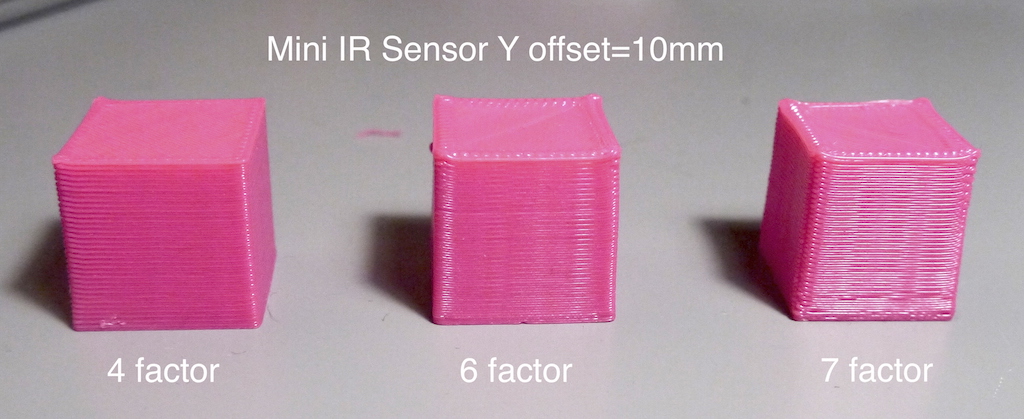
Now, when I do a 4 factor calibration everything works fine and I get a decent print. See the first photo. If I do a 6 factor calibration, the print is still good (although it looks *slightly* worse than the original) but if I perform a 7 factor, everything goes pear-shaped (almost literally). Hopefully you can see that the x-y dimensions of the nominal 20mm cube are reduced to 18.5mm although the height remains good. The sides are also curved.
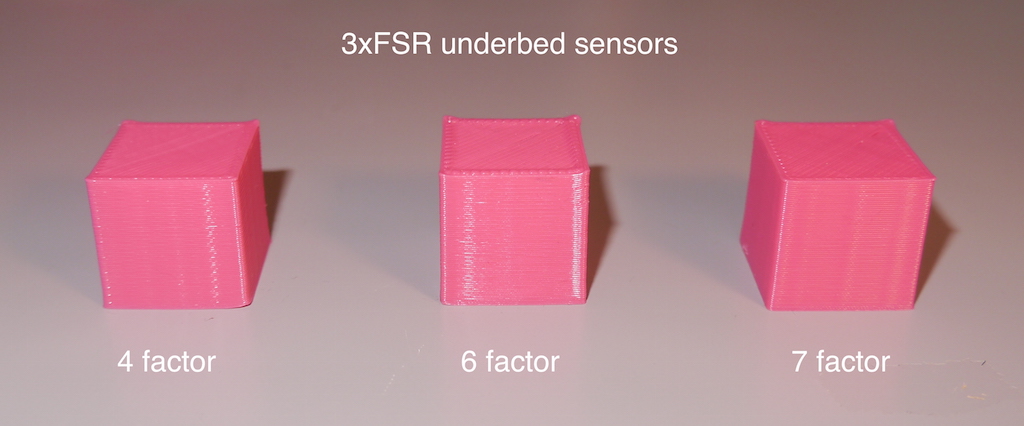
So I wasn't happy with this (even though the 4 factor was good enough) so I replaced the IR sensor with my old under bed FSR's (feeding into JohnSL's FSR board). Since these sense the nozzle directly, there is no probe offset. I repeated the experiment for 4, 6 and 7 factor calibration. See the second photo. Even though the 7 factor looks larger in the photo, it isn't and each of the cubes is dimensionally accurate to about 0.15mm.
Do you think there is any adjustment necessary to the calibration algorithm to account for the IR sensor offset? I still have the IR sensor attached to my effector so I can switch back if you need me to do any measurements. I'd actually like to go back to using the IR sensor if possible since it will allow me to fix the bed rigidly to the printer base, which isn't possible when using the FSRs.
best regards
M558 P1 X0 Y0 Z0.7
even though the actual Y offset is about 8mm.
Now, when I do a 4 factor calibration everything works fine and I get a decent print. See the first photo. If I do a 6 factor calibration, the print is still good (although it looks *slightly* worse than the original) but if I perform a 7 factor, everything goes pear-shaped (almost literally). Hopefully you can see that the x-y dimensions of the nominal 20mm cube are reduced to 18.5mm although the height remains good. The sides are also curved.
So I wasn't happy with this (even though the 4 factor was good enough) so I replaced the IR sensor with my old under bed FSR's (feeding into JohnSL's FSR board). Since these sense the nozzle directly, there is no probe offset. I repeated the experiment for 4, 6 and 7 factor calibration. See the second photo. Even though the 7 factor looks larger in the photo, it isn't and each of the cubes is dimensionally accurate to about 0.15mm.
Do you think there is any adjustment necessary to the calibration algorithm to account for the IR sensor offset? I still have the IR sensor attached to my effector so I can switch back if you need me to do any measurements. I'd actually like to go back to using the IR sensor if possible since it will allow me to fix the bed rigidly to the printer base, which isn't possible when using the FSRs.
best regards
|
Re: New Duet firmware with fast 7-factor delta calibration September 04, 2015 08:09PM |
Registered: 10 years ago Posts: 140 |
|
Re: New Duet firmware with fast 7-factor delta calibration September 05, 2015 02:23AM |
Registered: 9 years ago Posts: 445 |
Quote
bower-andy
@dc42, I have been using your mini IR sensor board with the n-factor auto-calibration and I'm seeing some strange effects which I'm starting to think are due to the offset of the probe location from the nozzle centre. As I think you have suggested, I have set the probe X, Y offsets to zero:
M558 P1 X0 Y0 Z0.7
even though the actual Y offset is about 8mm.
Now, when I do a 4 factor calibration everything works fine and I get a decent print. See the first photo. If I do a 6 factor calibration, the print is still good (although it looks *slightly* worse than the original) but if I perform a 7 factor, everything goes pear-shaped (almost literally). Hopefully you can see that the x-y dimensions of the nominal 20mm cube are reduced to 18.5mm although the height remains good. The sides are also curved.
best regards
Don't think the M558 command is used the set the offset, see this: [reprap.org]
I couldn't find it now but I have slight remembrance that dc42 posted that it is better to just use a 6 factor calibration, I believe you just have encountered the why to that.
|
Re: New Duet firmware with fast 7-factor delta calibration September 05, 2015 03:40AM |
Registered: 8 years ago Posts: 21 |
@Koenig,
Sorry, my bad. Yes, you're right the command is really:
G31 X0 Y0 Z0.7 P500
I'm pretty sure I was using this at the time, I just retyped the wrong line from config.g when preparing the above message.
It's interesting, though, that the 7 factor calibrate works well for me when the probe is central but not otherwise.
best regards
|
Re: New Duet firmware with fast 7-factor delta calibration September 05, 2015 03:50AM |
Registered: 10 years ago Posts: 14,672 |
Quote
bower-andy
@dc42, I have been using your mini IR sensor board with the n-factor auto-calibration and I'm seeing some strange effects which I'm starting to think are due to the offset of the probe location from the nozzle centre. As I think you have suggested, I have set the probe X, Y offsets to zero:
...
Do you think there is any adjustment necessary to the calibration algorithm to account for the IR sensor offset? I still have the IR sensor attached to my effector so I can switch back if you need me to do any measurements. I'd actually like to go back to using the IR sensor if possible since it will allow me to fix the bed rigidly to the printer base, which isn't possible when using the FSRs.
best regards
The calibration algorithm assumes that the bed is flat and that the machine has standard delta mechanics. Under those assumptions, the algorithm needs to know position of the centre of the effector, and the probe offset is irrelevant. This is not the same as a bed compensation algorithm, in which the aim is at least partly to compensate for a bed that isn't flat.
I no longer advise 7-factor auto calibration, because it turns out that changes to the configured diagonal rod length affect the flatness of the printing plane very little, once you make a corresponding change to the delta radius. So the diagonal rod length is not very well established by the probe errors, as you have discovered. I recommend 6-factor calibration instead.
What you are seeing with the IR probing is probably caused by the effector tilting slightly as it translates in the XY plane. I have found it very difficult to eliminate such tilt. It takes only a tiny tilt to change the Z offset of the sensor board relative to the nozzle by a significant amount, and hence change the trigger height. If you have the back of the board 8mm from the nozzle, then the sensitive region is probably about 14mm from the nozzle, and a 1 degree change in tilt will change the relative Z height by about 0.25mm.
Apart from trying to minimise the tilt, you can compensate for it in bed.g using the H parameter on the G30 command. See [reprap.org] for more. The way I establish the H offsets is:
1. Move the head to a probe point, then drop the head in 0.035mm steps until it just grips a piece of paper.
2. Send G92 Z0 to define that position as Z=0.
3. Raise the head to 5mm, remove the paper, and send G30 S-1 to establish the trigger height at that point.
4. Repeat step 3 a couple of times and take an average or the most common value (I get results consistent to 0.01mm).
Do this for all probe points. You can also use feeler gauges after step (2) to measure the gap between the bottom of the board and the bed, to check whether the trigger height changes are due to tilt or not. Use the trigger height at the centre of the bed as your Z parameter in the G31 command in config.g, and use the H parameter on the G30 commands in bed.g to adjust the trigger height offsets at the other points. The H parameter is the value you need to add to the trigger height defined in the G31 command to get the trigger height at that G30 probe point.
This procedure is also useful when using FSRs, because the nozzle force needed to trigger the FSRs typically varies with probing position, e.g. it is least when you probe near an FSR.
Depending on what firmware version you have, you may need to update your firmware to get support for the H parameter. Current firmware is 1.09i-dc42.
HTH David
Large delta printer [miscsolutions.wordpress.com], E3D tool changer, Robotdigg SCARA printer, Crane Quad and Ormerod
Disclosure: I design Duet electronics and work on RepRapFirmware, [duet3d.com].
|
Re: New Duet firmware with fast 7-factor delta calibration September 05, 2015 03:52AM |
Registered: 10 years ago Posts: 14,672 |
Quote
3DRapidClone
Hey DC42, is your current branch up to date with the X4 extension boards and the 4 additional extruders?
Yes, it always has handled the X4 extension board. The latest version handles the Duet 0.8.5 as well, so in priciple you can now have 6 extruders.
Large delta printer [miscsolutions.wordpress.com], E3D tool changer, Robotdigg SCARA printer, Crane Quad and Ormerod
Disclosure: I design Duet electronics and work on RepRapFirmware, [duet3d.com].
|
Re: New Duet firmware with fast 7-factor delta calibration September 05, 2015 03:53AM |
Registered: 10 years ago Posts: 14,672 |
Quote
Koenig
Quote
bower-andy
@dc42, I have been using your mini IR sensor board with the n-factor auto-calibration and I'm seeing some strange effects which I'm starting to think are due to the offset of the probe location from the nozzle centre. As I think you have suggested, I have set the probe X, Y offsets to zero:
M558 P1 X0 Y0 Z0.7
even though the actual Y offset is about 8mm.
Now, when I do a 4 factor calibration everything works fine and I get a decent print. See the first photo. If I do a 6 factor calibration, the print is still good (although it looks *slightly* worse than the original) but if I perform a 7 factor, everything goes pear-shaped (almost literally). Hopefully you can see that the x-y dimensions of the nominal 20mm cube are reduced to 18.5mm although the height remains good. The sides are also curved.
best regards
Don't think the M558 command is used the set the offset, see this: [reprap.org]
Correct, the X and Y probe offsets are set in the G31 command.
Edited 2 time(s). Last edit at 09/05/2015 03:53AM by dc42.
Large delta printer [miscsolutions.wordpress.com], E3D tool changer, Robotdigg SCARA printer, Crane Quad and Ormerod
Disclosure: I design Duet electronics and work on RepRapFirmware, [duet3d.com].


Sorry, only registered users may post in this forum.