Ebay SINTRON Kossel Mini full kit
Posted by Miamicraft
|
Re: Ebay SINTRON Kossel Mini full kit January 14, 2016 02:48AM |
Registered: 8 years ago Posts: 5,232 |
Another reason for a stepper to move further against endstop is a bad "DIR" pin connection.
After the first hit of the endstop, the stepper should reverse and move down a bit. Maybe that goes wrong in your case.
Try to swap steppers and endstops on your duet and see, if the error moves to the next tower.
-Olaf
After the first hit of the endstop, the stepper should reverse and move down a bit. Maybe that goes wrong in your case.
Try to swap steppers and endstops on your duet and see, if the error moves to the next tower.
-Olaf
|
Anonymous User
Re: Ebay SINTRON Kossel Mini full kit January 14, 2016 04:40AM |
Quote
hacker
Hmm… My homedelta.g has "G1 S1 X360 Y360 Z360 F2500" which significantly slower than 3500.
Hmmm.... My Homing is even much slower, because I had the Problem, when carriages are already homed, the ramming into the 3 Switches at the same time, moves Triggerlevel around.
So now my Stop Code after printing is G1 X10 Y20 Z210 F3000 (Max-Z=220) --> All 3 Carriages are at different heights, and away from the endstops.
When Starting Print, Homing is done with F800!
Since I do it this way, I never had to adjust M666 Endstop-Offsets anymore...
Only Restriction from this is: 10mm lower max printable Height.... - I don't care.
|
Re: Ebay SINTRON Kossel Mini full kit January 14, 2016 04:42AM |
Registered: 8 years ago Posts: 255 |
|
Re: Ebay SINTRON Kossel Mini full kit January 14, 2016 08:23AM |
Registered: 8 years ago Posts: 104 |
I never had a problem with homing. But I'm still on Sintron's RAMPS and Marlin. Looked in the settings and discovered that the default initial homing speed (when all carriages move up together) in Marlin is set to 8313.6mm/min (odd number, it's 1.732*80*60), then carriages individually do first touch on speed 4800 (80*60), and final touch speed is 1/10th of previous (480, or 80*60/10). And enstops are capable to catch carriages even on initial homing speed.
The longest print which I did till now, was a bit more than 8 hours.
Edited 1 time(s). Last edit at 01/14/2016 08:37AM by GrAndAG.
I depends on model to print. I.e. this well known one is 13cm tall, and prints in less than 2 hours.Quote
hacker
Quote
Sir_Death
Only Restriction from this is: 10mm lower max printable Height.... - I don't care.
As if otherwise I would have a patience to print something 20cm high ;-)
The longest print which I did till now, was a bit more than 8 hours.
Edited 1 time(s). Last edit at 01/14/2016 08:37AM by GrAndAG.
|
Anonymous User
Re: Ebay SINTRON Kossel Mini full kit January 14, 2016 09:13AM |
I'm on Sintron's RAMPS and Marlin too - only Firmware changed (moved to Rich Cattels and now on to Marlin 1.1.0 RC3)Quote
GrAndAG
I never had a problem with homing. But I'm still on Sintron's RAMPS and Marlin. Looked in the settings and discovered that the default initial homing speed (when all carriages move up together) in Marlin is set to 8313.6mm/min (odd number, it's 1.732*80*60), then carriages individually do first touch on speed 4800 (80*60), and final touch speed is 1/10th of previous (480, or 80*60/10). And enstops are capable to catch carriages even on initial homing speed.
With 4800 Initial homing Speed and already homed after last print, I had the Problem, the legs of the endstop Switches got slightly bent where they are soldered.
So after some 4800-homings I had some 1/100 to 1/10mm higher triggerlevel - resulting in first layer not sticking onto the printbed.
|
Re: Ebay SINTRON Kossel Mini full kit January 14, 2016 09:13AM |
Registered: 8 years ago Posts: 255 |
Quote
GrAndAG
I never had a problem with homing. But I'm still on Sintron's RAMPS and Marlin. Looked in the settings and discovered that the default initial homing speed (when all carriages move up together) in Marlin is set to 8313.6mm/min (odd number, it's 1.732*80*60), then carriages individually do first touch on speed 4800 (80*60), and final touch speed is 1/10th of previous (480, or 80*60/10). And enstops are capable to catch carriages even on initial homing speed.
I depends on model to print. I.e. this well known one is 13cm tall, and prints in less than 2 hours.Quote
hacker
Quote
Sir_Death
Only Restriction from this is: 10mm lower max printable Height.... - I don't care.
As if otherwise I would have a patience to print something 20cm high ;-)
The longest print which I did till now, was a bit more than 8 hours.
Of course there are exceptions (though I'm not sure if I'm planning to print this particular one
 ).
).
|
Re: Ebay SINTRON Kossel Mini full kit January 14, 2016 10:57AM |
Registered: 8 years ago Posts: 319 |
Quote
dc42
Quote
DRTak
Quote
Sir_Death
@DRTak:
Sounds to me you have some kind of contact-problem, self-healing when the machine is warm.
Check all the soldering Points for this endstop, check all the connectors, eventually endstop-switch is damaged - do you have a spare one to check? - or exchange with another towers endstop - by doing this part by part and watching, if the error goes with the part or stays at the tower, you may find the faulty contact/part...
Did all of the above. Repleaced the y endstop wires with new set. Replaced endstop with spare Sintron one. Still have ramming issue. Very odd.
I decided to install a new line of code for the homing function. I made it go slow for the last 170mm. So first line of code was S1 X150 Y150 Z150 3500, Second line was S1 X170 Y170 Z170 1000
That way when it gets close to the top, the carriages slow down to make good contact with the endstops. It kinda helps. Still rams into the endstop at first boot. But it appears that the extra line of code helps the issue to self resolve faster that without it.
I've only just noticed that you are talking about Duet electronics. Here's what I suggest:
The usual cause of motors not stopping during homing is that the motors and endstops do not correspond, for example because the X and Y endstop wires are swapped. So try the following test:
1. Test the endstop switches individually using M119, making sure that it reports "at max stop" for the correct switch when you press it.
2. With the motors off, slowly push the carriages up to the endstops and make sure that each carriage triggers the switch reliably (as confirmed using M119) before it jams against the switch body. If you are using wheeled carriages, make sure they cannot rotate to as to avoid triggering the switch.
3. Test the motors individually to make sure that commands to the XYZ motors move the correct motor. For example, if you place all the carriages 10mm below the endstops, then sending G91 followed by G1 S1 X20 F500 should move the X carriage up 20mm, butg it should stop at the endstop. Again, make sure it is the correct motor that moves.
Ok I did all of the above. Here are my results
1. I have issues See below
2. Passes test. Endstop triggers before being rammed (if warmed up for 10min)
3. Passes test. All correct motors are associated with correct endstops and axis
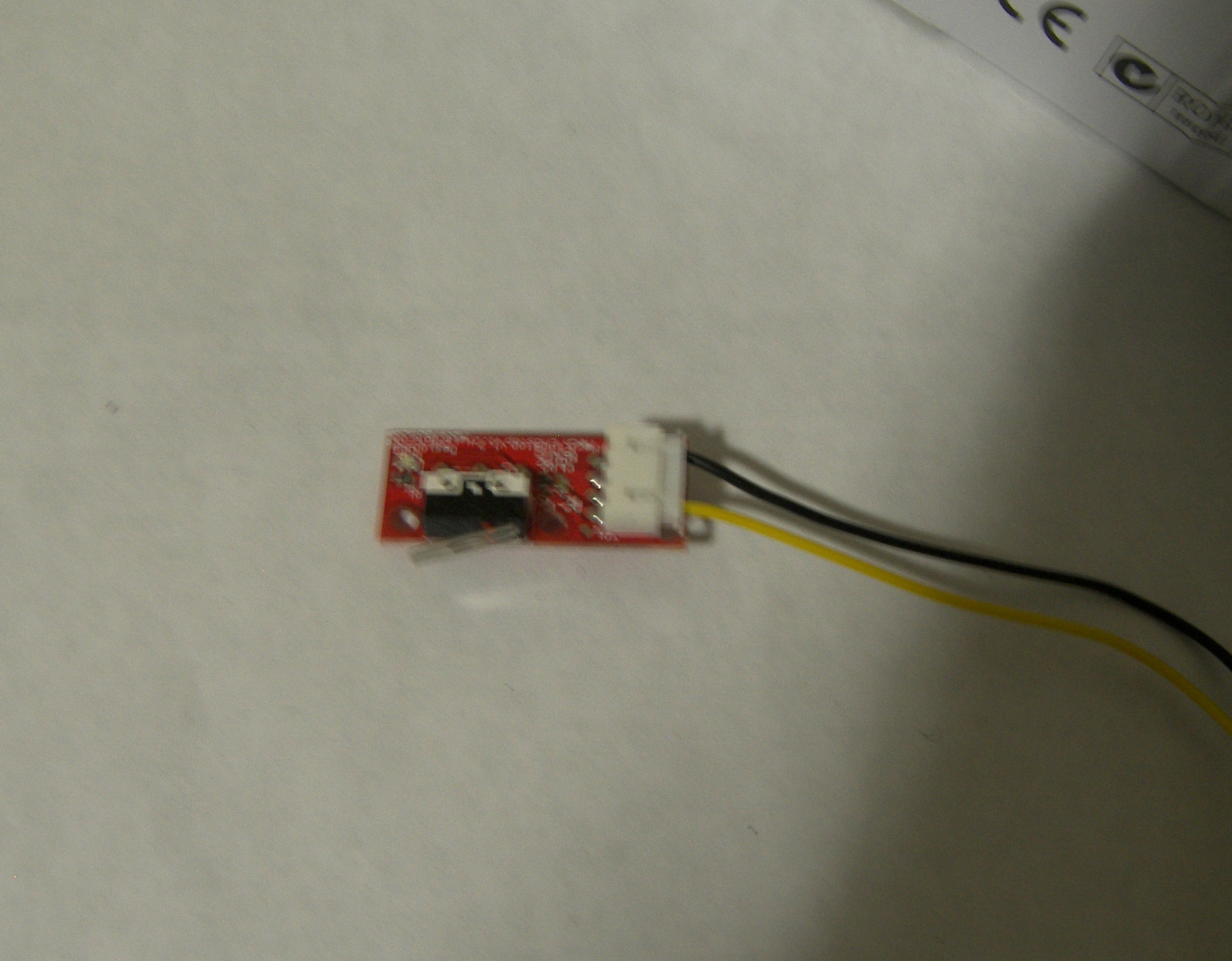
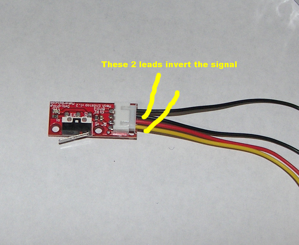
First boot up machine. X and Z endstop work and say at max stop. However, Y endstop sometimes says max stop and other times doesnt. It seems random. After 10min of warmup, the Y endstop starts to read a little more reliably. So I put in new wires on the Y axis and new Y endstop. Didnt fix the issue. My wiring for the X and Z endstop are the 2 outer wires from the endstop connect to the duet. Same for the Y endstop. I have attached a picture. The Y wiring is the black and yellow wire in the picture (I call it 1st and 4th wire). I have another picture attached. It is another idea that I have. If I connect the duet to the endstop with the wiring as shown in the last picture. The 1st and 3rd wire the polarity is reversed. So the light is OFF on the duet and the signal reads at max stop. But when you push the endstop the light turns on and it says not stopped. This works reliably. Maybe my duets internal electronics for the endstop is off? If I can make a code inside of config.g or homedelta to tell the machine to reverse polarity I can use the other wiring (1st and 3rd wires connected). This is a reliable signal. The thing that I noticed is that with the polarity of the endstop reversed. The light is completely off on the duet. When endstop is pushed it is completely ON.
The wiring for the 1st and 4th wire makes the red LED light always on. But when you push the endstop the red LED becomes dim but is not entirely off. But the signal reads at max endstop when the endstop is pushed.
Maybe in general my wiring is off?
Edited 2 time(s). Last edit at 01/14/2016 10:59AM by DRTak.
|
Re: Ebay SINTRON Kossel Mini full kit January 14, 2016 12:09PM |
Registered: 8 years ago Posts: 104 |
DRTak,
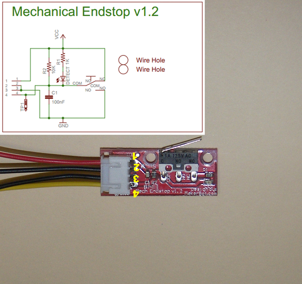
RAMPS uses 1-3 scheme (in your classification) for endstop wiring. The 4th wire (red in original cable) is used to light up the indicator LED on endstop PCB, and generally can be not wired without affecting endstop functionality.
The schematics of endstop (inputs numbering on the scheme is reversed in comparison with your post above):
Maybe for Duet all 3 wires have to be connected for proper operations: black to GND, red to +, yellow to signal pin.
[UPD]
And also look at M574 command, which, as I understand, configures endstops behavior..
Edited 6 time(s). Last edit at 01/14/2016 03:23PM by GrAndAG.
RAMPS uses 1-3 scheme (in your classification) for endstop wiring. The 4th wire (red in original cable) is used to light up the indicator LED on endstop PCB, and generally can be not wired without affecting endstop functionality.
The schematics of endstop (inputs numbering on the scheme is reversed in comparison with your post above):

Maybe for Duet all 3 wires have to be connected for proper operations: black to GND, red to +, yellow to signal pin.
[UPD]
And also look at M574 command, which, as I understand, configures endstops behavior..
Edited 6 time(s). Last edit at 01/14/2016 03:23PM by GrAndAG.
|
Re: Ebay SINTRON Kossel Mini full kit January 14, 2016 02:21PM |
Registered: 8 years ago Posts: 319 |
Oddly I have tried all 3 wires hooked up. It works great until the endstop is activated then the whole system reboots? So the RED LED light on the duet lights up correctly. But the second you touch the Y endstop it blinks and reboots itself. I assume it shorts itself out?
Tried M574 command and seemed to fix the issue.
However Added this line
M574 Y2 S0.
This inverted the Y tower endstop to accept a HIGH signal. So now it works. No more ramming into the carriage is amazing.
Thanks for the diagram GrAndAG. That really helped.
dc42 any ideas why this is the case?
I deleted the extra lines in the Homedelta.g . Dont need to slow it down when it goes to the top anymore.
Edited 3 time(s). Last edit at 01/14/2016 03:08PM by DRTak.
|
Re: Ebay SINTRON Kossel Mini full kit January 14, 2016 03:34PM |
Registered: 8 years ago Posts: 104 |
|
Re: Ebay SINTRON Kossel Mini full kit January 14, 2016 04:29PM |
Registered: 8 years ago Posts: 3 |
Hi all,
I now followed this thread till here and got some valuable information along the way. I also built a Sintron Kossel here, but went for the Duet 0.8.5 board from the start (Sintron did not accept my request to ship the kit without their IMHO crappy electronics).
What can I say until now:
Duet is not cheap but probably worth the money, as the RAMPS hardware issues I read about are non-existent. The firmware is great (hi DC42) and it essentially "just works".
About the Sintron kit: I am currently working on fixing the two major issues for me: the stock metal diagonal rods as well as the effector. Both problems have been mentioned here already: the rods are binding and the effector is not 40mm wide but 38,x instead, resulting in a small effector tilt.
I already ordered carbon rods as well as traxxas joints and will reprint the effector as soon as I can be sure it will print within some accuracy margins.
Also, the hotend gave me some headache at the beginning: it was clogged with PLA rather quickly and I had to disassemble it completely. I used this chance to get rid of the PTFE tube inside the heat break and drilled the top of the break to a 3mm diameter. Since then I can print and for a printer that was not calibrated with autolevel, I have to say I'm quite satisfied. I am now waiting for my new parts to arrive and expect an improved build quality and fewer problems.
|
Re: Ebay SINTRON Kossel Mini full kit January 14, 2016 04:39PM |
Registered: 8 years ago Posts: 319 |
Quote
chris81
Hi all,
I now followed this thread till here and got some valuable information along the way. I also built a Sintron Kossel here, but went for the Duet 0.8.5 board from the start (Sintron did not accept my request to ship the kit without their IMHO crappy electronics).
What can I say until now:
Duet is not cheap but probably worth the money, as the RAMPS hardware issues I read about are non-existent. The firmware is great (hi DC42) and it essentially "just works".
About the Sintron kit: I am currently working on fixing the two major issues for me: the stock metal diagonal rods as well as the effector. Both problems have been mentioned here already: the rods are binding and the effector is not 40mm wide but 38,x instead, resulting in a small effector tilt.
I already ordered carbon rods as well as traxxas joints and will reprint the effector as soon as I can be sure it will print within some accuracy margins.
Also, the hotend gave me some headache at the beginning: it was clogged with PLA rather quickly and I had to disassemble it completely. I used this chance to get rid of the PTFE tube inside the heat break and drilled the top of the break to a 3mm diameter. Since then I can print and for a printer that was not calibrated with autolevel, I have to say I'm quite satisfied. I am now waiting for my new parts to arrive and expect an improved build quality and fewer problems.
Hello Chris. You will see a major improvement when you replace those metal rods. I have not replaced my effector yet. I use this calculator to help me
[escher3d.com]
|
Re: Ebay SINTRON Kossel Mini full kit January 14, 2016 06:31PM |
Registered: 8 years ago Posts: 104 |
Ok, I'm not an electronics engineer, I have just basic understandings from school I graduated an ages ago. But I would like to understand how endstop works actually.
So, assuming the schematics above is correct (wires are colored (on endstop end) as: red - VCC (+), black - GND and yellow - signal).
The cases:
1) All 3 wires are correctly (+ to +, GND to GND, signal to signal) connected to Duet board. No pull-something resistors are enabled (M574 Y0). In this case all should work, as switch just simply connects VCC or GND to signal.
2) Only 2 wires are correctly connected (GND to GND, signal to signal), VCC is not connected. In this case the Duet pull-up resistor should be enabled (M574 Y2 S0). Otherwise the input will be "floating" until switch is pressed, so, the behavior of non-triggered switch is unpredictable.
3) All 3 wires are correctly (+ to +, GND to GND, signal to signal) wired. And pull-up resistor is enabled (M574 Y2).In this case we have 2 pull-up resistors in parallel, what leads to reduced total resistance. And when the switch is triggered, the current can be higher then safe limit, so it could be interprets as short, and the board could switch itself off. (Maybe it's one of DRTak's cases). All should work as in case 1).
4) All 3 wires are correctly (+ to +, GND to GND, signal to signal) wired. And, in this time, the pull-down resistor is enabled (M574 Y1). All should work as in case 1).
5) Only 2 wires are correctly connected (+ to +, signal to signal), GND is not connected. no resistors, or pull-up resistor is enabled. Will not work, as the input will be always "1".
6) Only 2 wires are correctly connected (+ to +, signal to signal), GND is not connected. Pull-down resistor is enabled. In this case we have voltage divider if switch is triggered. In ideal case (if endstop pull-up an board pull-down resistors are equivalent) it's 1/2 of VCC, which is not logical "0" nor "1". The state of input can be any. Non-workable wiring in general. (Maybe it's another of DRTak's cases). [UPD] Again forgot that there is LED's resistor. So, the level should still be "almost 1" if switch is triggered.
As result, I see 4 workable wiring and pull-something resistor configurations:
1) 3 wires, correct connection. No pull-something resistors. "0" level will mean triggered.
2) 2 wires (GND to GND, signal to signal). Pull-up resistor. "0" level will mean triggered.
3) 2 wires (endstop GND to board VCC(+) (Yes! ), signal to signal). Pull-down resistor. "1" level will mean triggered.
4) 3 wires, incorrect connection, VCC and GND are swapped (GND to VCC(+), VCC(+) to GND, signal to signal). No pull-something resistors. "1" level will mean triggered. Endstop LED will not work though.
Please correct me if I made mistakes.
Edited 6 time(s). Last edit at 01/14/2016 07:07PM by GrAndAG.
So, assuming the schematics above is correct (wires are colored (on endstop end) as: red - VCC (+), black - GND and yellow - signal).
The cases:
1) All 3 wires are correctly (+ to +, GND to GND, signal to signal) connected to Duet board. No pull-something resistors are enabled (M574 Y0). In this case all should work, as switch just simply connects VCC or GND to signal.
2) Only 2 wires are correctly connected (GND to GND, signal to signal), VCC is not connected. In this case the Duet pull-up resistor should be enabled (M574 Y2 S0). Otherwise the input will be "floating" until switch is pressed, so, the behavior of non-triggered switch is unpredictable.
3) All 3 wires are correctly (+ to +, GND to GND, signal to signal) wired. And pull-up resistor is enabled (M574 Y2).
4) All 3 wires are correctly (+ to +, GND to GND, signal to signal) wired. And, in this time, the pull-down resistor is enabled (M574 Y1). All should work as in case 1).
5) Only 2 wires are correctly connected (+ to +, signal to signal), GND is not connected. no resistors, or pull-up resistor is enabled. Will not work, as the input will be always "1".
6) Only 2 wires are correctly connected (+ to +, signal to signal), GND is not connected. Pull-down resistor is enabled. In this case we have voltage divider if switch is triggered. In ideal case (if endstop pull-up an board pull-down resistors are equivalent) it's 1/2 of VCC, which is not logical "0" nor "1". The state of input can be any. Non-workable wiring in general. (Maybe it's another of DRTak's cases). [UPD] Again forgot that there is LED's resistor. So, the level should still be "almost 1" if switch is triggered.
As result, I see 4 workable wiring and pull-something resistor configurations:
1) 3 wires, correct connection. No pull-something resistors. "0" level will mean triggered.
2) 2 wires (GND to GND, signal to signal). Pull-up resistor. "0" level will mean triggered.
3) 2 wires (endstop GND to board VCC(+) (Yes!
), signal to signal). Pull-down resistor. "1" level will mean triggered.4) 3 wires, incorrect connection, VCC and GND are swapped (GND to VCC(+), VCC(+) to GND, signal to signal). No pull-something resistors. "1" level will mean triggered. Endstop LED will not work though.
Please correct me if I made mistakes.
Edited 6 time(s). Last edit at 01/14/2016 07:07PM by GrAndAG.
|
Re: Ebay SINTRON Kossel Mini full kit January 14, 2016 06:32PM |
Registered: 8 years ago Posts: 319 |
|
Re: Ebay SINTRON Kossel Mini full kit January 15, 2016 03:04AM |
Registered: 8 years ago Posts: 5,232 |
Could you please start a new topic with all these duet migration problems? It starts to get messy here....
@DRTak it is obvious to me, your duet board has connectivity problems.
Check the board for cold solder or broken traces, don't mess around with different endstop wiring. You only risk to damage your board even more.
THX
-Olaf
@DRTak it is obvious to me, your duet board has connectivity problems.
Check the board for cold solder or broken traces, don't mess around with different endstop wiring. You only risk to damage your board even more.
THX
-Olaf
|
Re: Ebay SINTRON Kossel Mini full kit January 15, 2016 06:04AM |
Registered: 10 years ago Posts: 14,672 |
Quote
GrAndAG
DRTak,
RAMPS uses 1-3 scheme (in your classification) for endstop wiring. The 4th wire (red in original cable) is used to light up the indicator LED on endstop PCB, and generally can be not wired without affecting endstop functionality.
The schematics of endstop (inputs numbering on the scheme is reversed in comparison with your post above):
[attachment 69772 Mech_Endstop-F.png]
Maybe for Duet all 3 wires have to be connected for proper operations: black to GND, red to +, yellow to signal pin.
Yes, with those endstops you should connect all 3 wires. Connect pin 1 on that diagram to the centre pin on the endstop connector, the one marked 3V3. Connect pin 2 or 3 to the GND endstop pin, and pin 4 to the STP pin. The pin names are marked on the underside of the Duet.
In config.g for a delta you should have M574 X2 Y2 Z2 S1 if you have the usual active high endstops, or M574 X2 Y2 Z2 S0 if yours are active low. If the LED on the endstop board lights up when the endstop switch is triggered, the output is active low.
Large delta printer [miscsolutions.wordpress.com], E3D tool changer, Robotdigg SCARA printer, Crane Quad and Ormerod
Disclosure: I design Duet electronics and work on RepRapFirmware, [duet3d.com].
|
Re: Ebay SINTRON Kossel Mini full kit January 15, 2016 12:08PM |
Registered: 8 years ago Posts: 319 |
Quote
GrAndAG
Ok, I'm not an electronics engineer, I have just basic understandings from school I graduated an ages ago. But I would like to understand how endstop works actually.
So, assuming the schematics above is correct (wires are colored (on endstop end) as: red - VCC (+), black - GND and yellow - signal).
The cases:
1) All 3 wires are correctly (+ to +, GND to GND, signal to signal) connected to Duet board. No pull-something resistors are enabled (M574 Y0). In this case all should work, as switch just simply connects VCC or GND to signal.
2) Only 2 wires are correctly connected (GND to GND, signal to signal), VCC is not connected. In this case the Duet pull-up resistor should be enabled (M574 Y2 S0). Otherwise the input will be "floating" until switch is pressed, so, the behavior of non-triggered switch is unpredictable.
3) All 3 wires are correctly (+ to +, GND to GND, signal to signal) wired. And pull-up resistor is enabled (M574 Y2).In this case we have 2 pull-up resistors in parallel, what leads to reduced total resistance. And when the switch is triggered, the current can be higher then safe limit, so it could be interprets as short, and the board could switch itself off. (Maybe it's one of DRTak's cases). All should work as in case 1).
4) All 3 wires are correctly (+ to +, GND to GND, signal to signal) wired. And, in this time, the pull-down resistor is enabled (M574 Y1). All should work as in case 1).
5) Only 2 wires are correctly connected (+ to +, signal to signal), GND is not connected. no resistors, or pull-up resistor is enabled. Will not work, as the input will be always "1".
6) Only 2 wires are correctly connected (+ to +, signal to signal), GND is not connected. Pull-down resistor is enabled. In this case we have voltage divider if switch is triggered. In ideal case (if endstop pull-up an board pull-down resistors are equivalent) it's 1/2 of VCC, which is not logical "0" nor "1". The state of input can be any. Non-workable wiring in general. (Maybe it's another of DRTak's cases). [UPD] Again forgot that there is LED's resistor. So, the level should still be "almost 1" if switch is triggered.
As result, I see 4 workable wiring and pull-something resistor configurations:
1) 3 wires, correct connection. No pull-something resistors. "0" level will mean triggered.
2) 2 wires (GND to GND, signal to signal). Pull-up resistor. "0" level will mean triggered.
3) 2 wires (endstop GND to board VCC(+) (Yes!
4) 3 wires, incorrect connection, VCC and GND are swapped (GND to VCC(+), VCC(+) to GND, signal to signal). No pull-something resistors. "1" level will mean triggered. Endstop LED will not work though.
Please correct me if I made mistakes.
Nice permutation. Here is the result.
1) 3 wires, correct connection. No pull-something resistors. "0" level will mean triggered.
Three wires connected as dc42 mentioned results in NO LED lights on for the stepper motor on the duet or duex4. However, when the endstop is triggered, the system reboots and the other red LED lights are on. Also ALL the orange LED lights are on on the duex4. NO stepper motor lights turn on for the duet when the endstop is triggered. When the endstop is released the system shuts off (all of my fans on the effector shut off).
2) 2 wires (GND to GND, signal to signal). Pull-up resistor. "0" level will mean triggered.
This is correct and what I am currently using for my Y tower. NO LED light when endstop is not activated. When endstop is triggered, the red LED for the stepper motor is on.
I did a variation of this just to see. GND to GND and STP (signal) to STP. Level 1. Registers as at max stop = no endstop activated. Registers not stopped = endstop activated.
3) 2 wires (endstop GND to board VCC(+) (Yes!
), signal to signal). Pull-down resistor. "1" level will mean triggered.Endstop not activated= NO LED Light for the stepper motor. Registers as at max stop. When the endstop is triggered= No red LED light. Still registers as at max stop
I did a variation of this just to see. GND to board VCC and STP (signal) to STP. Level 0. Registers as not stopped = no endstop activated. Registers not stopped = endstop activated.
4) 3 wires, incorrect connection, VCC and GND are swapped (GND to VCC(+), VCC(+) to GND, signal to signal). No pull-something resistors. "1" level will mean triggered. Endstop LED will not work though.
Interesting one. Pin1= red cable = power. Pin2 blank. Pin3=GND=black wire. Pin4=STP= yellow wire. If wired as above #4. endstop not activated. RED LED on stepper motor is red. Turns all of my fans on. However, when you push the endstop to active. The system reboots and turns itself backon and shuts all the fans off. Console reads when endstop is not active. not stopped. When endstop activated. I cannot get a reading because the system is rebooting and resets itself.
Edited 2 time(s). Last edit at 01/15/2016 12:13PM by DRTak.
|
Re: Ebay SINTRON Kossel Mini full kit January 15, 2016 12:38PM |
Registered: 8 years ago Posts: 1 |
I finally got my printer running! After about 3 weeks and at least 20 hours of work, I got my sintron kit to run the way it's supposed to:
[youtu.be]
[youtu.be]
Unfortunately, it is nearly impossible to get it running with just stock parts. Here is what you need:
- washer/spacers for the wheels so the sliders don't rub
- a newer version of marlin. Use the config from the sintron firmware to fill out a new one. I used [github.com] Which is built specifically for deltas
- Either a working auto level probe, different bed mounts that allow you to adjust it manually, or adjust the endstops to be equal distances from the bed. The stock version of marlin always crashed into the bed or would not work in some other way.
-turn down "duty cycle" for the bed in the firmware, otherwise the polyfuse overheats. Even with the 30amp power supply I am using.
- the switch to change from 220 to 110v is inside the power supply. It took me a while to figure out why the voltage was at 9v, but then I found the switch.
- READ AT LEAST MOST of this forum topic. It is extremely useful.
I also made these mods:
- (fake) e3d Volcano for $8
- e3d v6 clone heatsink and throat (so I can print polycarbonate), still in the mail
- fan mount that also blows on print. Greatly increases the quality of PLA parts. Mine doesn't fit (see pictures) because the spacing isn't right on the heatsink/throat
- replaced the z probe Allen key with an inductive sensor from aliexpress for $2
- geared extruder. The stock direct drive would kink ABS filament and stop constantly while I was using the stock e3d v5, and it didn't run the volcano at all. [www.thingiverse.com]
- Ramps & LCD case (yet to be printed at the time of the writing of this article)
- In the video above, I am printing a new spool holder.
I am using Repetierhost Host with Slic3r. I can share config files if needed. Feel free to ask any questions!
Also, I am having some issues with infill meeting up with the perimeters. I have since made rod length adjustments but I dont think that was the problem. Any ideas why?
Edited 2 time(s). Last edit at 01/15/2016 12:59PM by zakakazee@gmail.com.
[youtu.be]
[youtu.be]
Unfortunately, it is nearly impossible to get it running with just stock parts. Here is what you need:
- washer/spacers for the wheels so the sliders don't rub
- a newer version of marlin. Use the config from the sintron firmware to fill out a new one. I used [github.com] Which is built specifically for deltas
- Either a working auto level probe, different bed mounts that allow you to adjust it manually, or adjust the endstops to be equal distances from the bed. The stock version of marlin always crashed into the bed or would not work in some other way.
-turn down "duty cycle" for the bed in the firmware, otherwise the polyfuse overheats. Even with the 30amp power supply I am using.
- the switch to change from 220 to 110v is inside the power supply. It took me a while to figure out why the voltage was at 9v, but then I found the switch.
- READ AT LEAST MOST of this forum topic. It is extremely useful.
I also made these mods:
- (fake) e3d Volcano for $8
- e3d v6 clone heatsink and throat (so I can print polycarbonate), still in the mail
- fan mount that also blows on print. Greatly increases the quality of PLA parts. Mine doesn't fit (see pictures) because the spacing isn't right on the heatsink/throat
- replaced the z probe Allen key with an inductive sensor from aliexpress for $2
- geared extruder. The stock direct drive would kink ABS filament and stop constantly while I was using the stock e3d v5, and it didn't run the volcano at all. [www.thingiverse.com]
- Ramps & LCD case (yet to be printed at the time of the writing of this article)
- In the video above, I am printing a new spool holder.
I am using Repetierhost Host with Slic3r. I can share config files if needed. Feel free to ask any questions!
Also, I am having some issues with infill meeting up with the perimeters. I have since made rod length adjustments but I dont think that was the problem. Any ideas why?

Edited 2 time(s). Last edit at 01/15/2016 12:59PM by zakakazee@gmail.com.
|
Re: Ebay SINTRON Kossel Mini full kit January 15, 2016 03:04PM |
Registered: 8 years ago Posts: 319 |
|
Re: Ebay SINTRON Kossel Mini full kit January 15, 2016 03:22PM |
Registered: 8 years ago Posts: 319 |
Quote
o_lampe
Could you please start a new topic with all these duet migration problems? It starts to get messy here....
@DRTak it is obvious to me, your duet board has connectivity problems.
Check the board for cold solder or broken traces, don't mess around with different endstop wiring. You only risk to damage your board even more.
THX
-Olaf
I took apart the electronics again for the wiring issues. I checked the duet0.6 soldering. It all looked good below. Just in case though I resoldered the STP, V3, and GND for the endstop inputs. Put it all back together and Retested it and it didnt help.
|
Re: Ebay SINTRON Kossel Mini full kit January 15, 2016 07:18PM |
Registered: 10 years ago Posts: 14,672 |
Quote
DRTak
...
Nice permutation. Here is the result.
1) 3 wires, correct connection. No pull-something resistors. "0" level will mean triggered.
Three wires connected as dc42 mentioned results in NO LED lights on for the stepper motor on the duet or duex4. However, when the endstop is triggered, the system reboots and the other red LED lights are on. Also ALL the orange LED lights are on on the duex4. NO stepper motor lights turn on for the duet when the endstop is triggered. When the endstop is released the system shuts off (all of my fans on the effector shut off).
Then either there is a short on your Duet, or your endstop board does not match the schematic here [forums.reprap.org]. As the fault goes away after a while, I'm leaning to the view that you have a a short on or near the Duet endstop connector that clears when the board heats up, probably between the STP pin and ground. Some suggestions:
1. If you swap over the X and Y endstop connectors on the Duet, does the problem move to the X tower endstop switch (which should show up as Y triggered in M119), or does it stay on the Y switch (which should show up as X triggered in M119)?
2. Use a multimeter to check the resistance between STP and GND, and between STP and 3V3 when the board is cold and un-powered (including from USB ) and the endstop disconnected.
Edited 1 time(s). Last edit at 01/15/2016 07:19PM by dc42.
Large delta printer [miscsolutions.wordpress.com], E3D tool changer, Robotdigg SCARA printer, Crane Quad and Ormerod
Disclosure: I design Duet electronics and work on RepRapFirmware, [duet3d.com].
|
Re: Ebay SINTRON Kossel Mini full kit January 15, 2016 07:29PM |
Registered: 8 years ago Posts: 319 |
Quote
dc42
Quote
DRTak
...
Nice permutation. Here is the result.
1) 3 wires, correct connection. No pull-something resistors. "0" level will mean triggered.
Three wires connected as dc42 mentioned results in NO LED lights on for the stepper motor on the duet or duex4. However, when the endstop is triggered, the system reboots and the other red LED lights are on. Also ALL the orange LED lights are on on the duex4. NO stepper motor lights turn on for the duet when the endstop is triggered. When the endstop is released the system shuts off (all of my fans on the effector shut off).
Then either there is a short on your Duet, or your endstop board does not match the schematic here [forums.reprap.org]. As the fault goes away after a while, I'm leaning to the view that you have a a short on or near the Duet endstop connector that clears when the board heats up, probably between the STP pin and ground. Some suggestions:
1. If you swap over the X and Y endstop connectors on the Duet, does the problem move to the X tower endstop switch (which should show up as Y triggered in M119), or does it stay on the Y switch (which should show up as X triggered in M119)?
2. Use a multimeter to check the resistance between STP and GND, and between STP and 3V3 when the board is cold and un-powered (including from USB ) and the endstop disconnected.
For #1. If I switch the wires over to say the X tower. The problem moves to the X tower. So I connect the X endstop lead to the Duet0.6 board Y endstop connection on the board. When I home, the x tower shakes from the carraige ramming into the endstop.
#2. Im in the middle of a print so I have to wait til it is done.
|
Re: Ebay SINTRON Kossel Mini full kit January 16, 2016 12:41PM |
Registered: 8 years ago Posts: 319 |
2. Use a multimeter to check the resistance between STP and GND, and between STP and 3V3 when the board is cold and un-powered (including from USB ) and the endstop disconnected.
STP and GND is 0.8ohms with the endstop lead attached to the endstop.
STP and GND is OL? whatever that is with the endstop lead disconnected from the endstop
STP and 3V3 is OL? whatever that is with the endstop lead disconnected from the endstop
STP and 3V3 is OL? whatever that is with the endstop lead connected to the endstop
|
Re: Ebay SINTRON Kossel Mini full kit January 16, 2016 03:15PM |
Registered: 8 years ago Posts: 41 |
Quote
GrAndAG
Quote
gkr
Hello GrAndAG,
Do you mind posting a dump of the "full" Slic3r config from your 1.1.7 setup?Quote
GrAndAG
Hmm... Tried both 1.1.7 and 1.2.9. And could not find any significant differences in printing results. Both of them produce good g-code.
I would like to compare a few things with what I have.
Much appreciated.
Regards.
Configs for both Slic3r versions are attached (they are almost identical).
Hello GrAndAG (or anyone else):
What E-steps value are you guys using?
Currently, I have it as 110:
#define DEFAULT_AXIS_STEPS_PER_UNIT {79, 79, 79, 110}
But, I'm thinking that might be too high, and it's trying to force too much filament through the nozzle, than the nozzle can handle. So, suddenly midway thru the print, I see that the extrusion stops (especially on long prints). I think originally Sintron had it at 95.
Wondering what values you guys are using?
Thanks,
Ganesh
|
Re: Ebay SINTRON Kossel Mini full kit January 16, 2016 03:30PM |
Registered: 8 years ago Posts: 138 |
|
Re: Ebay SINTRON Kossel Mini full kit January 16, 2016 03:47PM |
Registered: 8 years ago Posts: 255 |
Quote
gkr
Quote
GrAndAG
Quote
gkr
Hello GrAndAG,
Do you mind posting a dump of the "full" Slic3r config from your 1.1.7 setup?Quote
GrAndAG
Hmm... Tried both 1.1.7 and 1.2.9. And could not find any significant differences in printing results. Both of them produce good g-code.
I would like to compare a few things with what I have.
Much appreciated.
Regards.
Configs for both Slic3r versions are attached (they are almost identical).
Hello GrAndAG (or anyone else):
What E-steps value are you guys using?
Currently, I have it as 110:
#define DEFAULT_AXIS_STEPS_PER_UNIT {79, 79, 79, 110}
But, I'm thinking that might be too high, and it's trying to force too much filament through the nozzle, than the nozzle can handle. So, suddenly midway thru the print, I see that the extrusion stops (especially on long prints). I think originally Sintron had it at 95.
Wondering what values you guys are using?
Thanks,
Ganesh
I think it was around 100 or 104 (now I have changed extruder). Why don't you just measure it?
|
Re: Ebay SINTRON Kossel Mini full kit January 16, 2016 04:05PM |
Registered: 8 years ago Posts: 41 |
|
Re: Ebay SINTRON Kossel Mini full kit January 16, 2016 04:10PM |
Registered: 8 years ago Posts: 89 |
|
Re: Ebay SINTRON Kossel Mini full kit January 16, 2016 04:11PM |
Registered: 8 years ago Posts: 255 |
Quote
gkr
Hello Hacker,
Can you please describe the process you are using to measure the E-Steps?
Regards.
This one, for example: [reprap.org] (the "Extruder steps" part).
Basically, you extrude a certain amount of filament, compare the theoretical filament advance and measured one and adjust your e-steps accordingly.
Your actual extruded filament may differ, because you calibrate the length of filament being extruded, you normally do further adjustments in slicer's extrusion multiplier (or flow multiplier or whatever it's called), since it's filament specific then and isn't about extruder, though since it has the same effect as changing e-steps you can see that some people prefer to adjust e-steps for spools as well.
|
Re: Ebay SINTRON Kossel Mini full kit January 16, 2016 05:52PM |
Registered: 8 years ago Posts: 41 |


Sorry, only registered users may post in this forum.