Optimum Arm Spacing
Posted by Dave_robinson_022
|
Optimum Arm Spacing September 24, 2015 05:05AM |
Registered: 9 years ago Posts: 25 |
Hi All, been a while.
I have read enough to calculate optimum arm length for delta radius on a large(ish) printer (1000mm height, 300mm build plate) but I can't seem to find anything on the ideal space between arms on the carriage and effector.
What is the suggested distance?
I am using Openbuilds mini v-wheel carriages so I can either work in or out from 50mm.
I am planning on using an E3D Chimera hotend so not a lot of space on the effector would be required.
|
Re: Optimum Arm Spacing September 24, 2015 05:06AM |
Registered: 9 years ago Posts: 25 |
|
Re: Optimum Arm Spacing September 24, 2015 08:07AM |
Registered: 10 years ago Posts: 14,672 |
The arm spacing is a compromise. Larger spacing makes the structure more rigid. But larger spacing requires a bigger effector, so the nozzle can't get so close to the towers and the print radius is reduced. My printer is about the same size as yours and the arm spacing is about 45mm, but a larger spacing would be better for this size printer. I suggest about 60mm.
Large delta printer [miscsolutions.wordpress.com], E3D tool changer, Robotdigg SCARA printer, Crane Quad and Ormerod
Disclosure: I design Duet electronics and work on RepRapFirmware, [duet3d.com].
Large delta printer [miscsolutions.wordpress.com], E3D tool changer, Robotdigg SCARA printer, Crane Quad and Ormerod
Disclosure: I design Duet electronics and work on RepRapFirmware, [duet3d.com].
|
Re: Optimum Arm Spacing September 25, 2015 05:16AM |
Registered: 10 years ago Posts: 732 |
|
Re: Optimum Arm Spacing September 25, 2015 06:30AM |
Registered: 9 years ago Posts: 25 |
|
Re: Optimum Arm Spacing September 25, 2015 06:46AM |
Registered: 10 years ago Posts: 14,672 |
Yes, my suggestion of 60mm was between arm centres. But as hercek says, larger is better if you don't mind the loss of print radius, or if there are other reasons why you need a larger effector.
Large delta printer [miscsolutions.wordpress.com], E3D tool changer, Robotdigg SCARA printer, Crane Quad and Ormerod
Disclosure: I design Duet electronics and work on RepRapFirmware, [duet3d.com].
Large delta printer [miscsolutions.wordpress.com], E3D tool changer, Robotdigg SCARA printer, Crane Quad and Ormerod
Disclosure: I design Duet electronics and work on RepRapFirmware, [duet3d.com].
|
Re: Optimum Arm Spacing September 25, 2015 07:32PM |
Registered: 9 years ago Posts: 483 |
Effector size also depends on whether you want the heat sink above or below the effector. If you have it above, then you need enough space to add a print cooling fan without interfering with the arms.
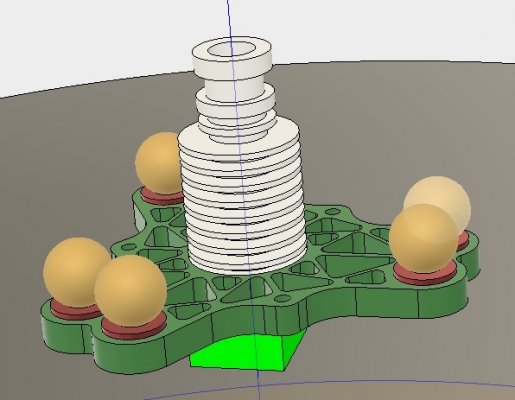
My delta has slightly over 300mm build circle, 350mm carbon fiber arms, and heat sink above the effector. The arms are 60mm apart and the 14mm balls on the effector have a minimum distance between them of 1.25mm.
Everything except the extrusions was done on a CNC router.
My delta has slightly over 300mm build circle, 350mm carbon fiber arms, and heat sink above the effector. The arms are 60mm apart and the 14mm balls on the effector have a minimum distance between them of 1.25mm.
Everything except the extrusions was done on a CNC router.
|
Re: Optimum Arm Spacing September 28, 2015 06:33AM |
Registered: 9 years ago Posts: 25 |
|
Re: Optimum Arm Spacing September 28, 2015 01:13PM |
Registered: 9 years ago Posts: 70 |
|
Re: Optimum Arm Spacing September 28, 2015 01:17PM |
Registered: 9 years ago Posts: 483 |
This should make it clear: [img.photobucket.com]
|
Re: Optimum Arm Spacing September 29, 2015 12:52AM |
Registered: 9 years ago Posts: 25 |
|
Re: Optimum Arm Spacing September 29, 2015 02:08AM |
Registered: 9 years ago Posts: 483 |
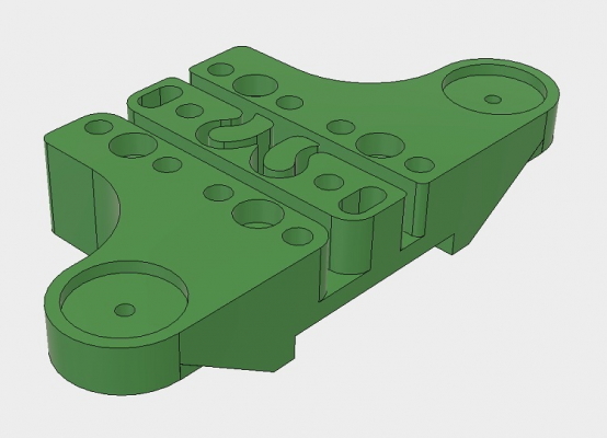
This will probably give you a better idea of how the effector was made:
It's 6.35mm thick, but 4mm would probably be rigid enough. The aluminum portion weighs 23 grams and the ball bearings and magnets add another 160 grams.
I used 30 degree extrusions from Misumi to build the corner brackets. Misumi doesn't have any pre-made connectors to use these, so I through bolted them to 2550 extrusions. I had to make several jigs to hold the 30 degree extrusions in place while bolting them. While the frame ended up being perfectly aligned (at least as well as I can measure it ), I hesitate to recommend doing the corners this way. The motor mounts were made from 1.5"x3" rectangular tubing and bolted to the lower top and bottom plates and to the vertical extrusion, so add a lot of rigidity to the frame.
The carriages were also CNC'd:
|
Re: Optimum Arm Spacing September 29, 2015 03:20AM |
Registered: 9 years ago Posts: 445 |
Quote
Dave_robinson_022
With you now. What thickness is your effector, I am trying to design to be as light as possible without compromising rigidity? Also, I would be interested in seeing what you did for frame corners as I am trying to come up with a simple design to CNC mill now?
For metal corners you should look into these: [github.com]
Edited 1 time(s). Last edit at 09/29/2015 03:21AM by Koenig.
|
Re: Optimum Arm Spacing September 29, 2015 05:03AM |
Registered: 8 years ago Posts: 5,232 |
When I see, how much weight the ball bearings/magnets add, I would go for hollow balls and spring loaded rods instead.
Has anyone tried to drill a hole in the balls? It´s mild steel ...Are they available in aluminum?
Then place the ball with the hole aiming away from the rods contact area.
-Olaf
Has anyone tried to drill a hole in the balls? It´s mild steel ...Are they available in aluminum?
Then place the ball with the hole aiming away from the rods contact area.
-Olaf
|
Re: Optimum Arm Spacing September 29, 2015 10:03AM |
Registered: 10 years ago Posts: 732 |
Just go for proper angle ball joints. Not TRAXXAS. Find a local store with parts for RC model cars/planes/helicopters. There will be a lot of high quality assembled ball joints there. They are extremely light, strong, and tight. No springs are needed. No heavy magnets which are going to rattle or even disconnect from time to time at higher accelerations.
|
Re: Optimum Arm Spacing September 29, 2015 11:55AM |
Registered: 8 years ago Posts: 5,232 |
|
Re: Optimum Arm Spacing September 29, 2015 01:32PM |
Registered: 9 years ago Posts: 483 |
There was a typo in my last post, the effector with 14mm balls and .5in ring magnets weighs 110 grams, not 180 grams 
I looked at using Traxxas balls, but the ones I purchased weren't very spherical. They probably would work fine as the contact area is pretty small. I also thought about using a single ball at each corner, but it would weigh quite a bit more. This would be the perfect candidate for hollowing.
The 25000 corners should work well, but they're not really very good for CNC'ing unless you also have a brake.
My effector and carriage design have a provision for adding a tensioning spring if the magnets don't provide enough holding force.
|
Re: Optimum Arm Spacing September 30, 2015 01:59AM |
Registered: 8 years ago Posts: 5,232 |
Sorry, only registered users may post in this forum.

