Delta homing issues
Posted by Code
|
Delta homing issues December 15, 2015 10:54PM |
Registered: 8 years ago Posts: 7 |
Hello all, I'm working on the initial setup of my delta and I'm kinda lost. This is my first 3d printer build (first printer as well). Anyhow I'm having issues get it to move correctly and home. I figured a video would be the best way to describe my issues. Not really sure where to start so any advice would be great. The video isn't great unfortunately.Thank you.
[youtu.be]
[youtu.be]
|
Re: Delta homing issues December 16, 2015 08:43AM |
Registered: 8 years ago Posts: 197 |
|
Re: Delta homing issues December 16, 2015 03:01PM |
Registered: 8 years ago Posts: 22 |
|
Re: Delta homing issues December 16, 2015 07:06PM |
Registered: 8 years ago Posts: 7 |
Thanks for the replies! I'll do my best to answer them
xile6:
When i lower the carriage so all end stops are open I receive all open when I send m119. When I raise it so that all end stops are closed i receive the following. I hadn't noticed that the z_min value was open when testing before. Would this be caused by the auto-leveling being enabled in my firmware? I'll have to read up on that more but I think for testing i should probably disable auto-leveling since it's more to debug.
18:40:29.981 : Reporting endstop status
18:40:29.981 : x_max: TRIGGERED
18:40:29.985 : y_max: TRIGGERED
18:40:29.985 : z_min: open
18:40:29.985 : z_max: TRIGGERED
Billhc83:
I was thinking the same thing I went through and changed the HOME_DIR flag, as well as the INVERT_(X,Y,Z)_DIR booleans with no effect. I did notice though that while it's still not homing correctly when in repetier pressing z down now moves the entire carriage down when last night it would not (pressing up did though) so there's some progress!
Should i disable the EEPROM while testing? I may save off this version of marlin and start fresh. Below is my config file...
Thank you all for the help!!
#include
#ifndef CONFIGURATION_H
#define CONFIGURATION_H
// This configuration file contains the basic settings.
// Advanced settings can be found in Configuration_adv.h
// BASIC SETTINGS: select your board type, temperature sensor type, axis scaling, and endstop configuration
// User-specified version info of this build to display in [Pronterface, etc] terminal window during
// startup. Implementation of an idea by Prof Braino to inform user that any changes made to this
// build by the user have been successfully uploaded into firmware.
#define STRING_VERSION_CONFIG_H __DATE__ " " __TIME__ // build date and time
#define STRING_CONFIG_H_AUTHOR "(RichCattell, Mini Kossel)" // Who made the changes.
// SERIAL_PORT selects which serial port should be used for communication with the host.
// This allows the connection of wireless adapters (for instance) to non-default port pins.
// Serial port 0 is still used by the Arduino bootloader regardless of this setting.
#define SERIAL_PORT 0
// This determines the communication speed of the printer
#define BAUDRATE 250000
//#define BAUDRATE 115200
//// The following define selects which electronics board you have. Please choose the one that matches your setup
// 10 = Gen7 custom (Alfons3 Version) "https://github.com/Alfons3/Generation_7_Electronics"
// 11 = Gen7 v1.1, v1.2 = 11
// 12 = Gen7 v1.3
// 13 = Gen7 v1.4
// 3 = MEGA/RAMPS up to 1.2 = 3
// 33 = RAMPS 1.3 / 1.4 (Power outputs: Extruder, Fan, Bed)
// 34 = RAMPS 1.3 / 1.4 (Power outputs: Extruder0, Extruder1, Bed)
// 35 = RAMPS 1.3 / 1.4 (Power outputs: Extruder, Fan, Fan)
// 4 = Duemilanove w/ ATMega328P pin assignment
// 5 = Gen6
// 51 = Gen6 deluxe
// 6 = Sanguinololu < 1.2
// 62 = Sanguinololu 1.2 and above
// 63 = Melzi
// 64 = STB V1.1
// 65 = Azteeg X1
// 66 = Melzi with ATmega1284 (MaKr3d version)
// 7 = Ultimaker
// 71 = Ultimaker (Older electronics. Pre 1.5.4. This is rare)
// 77 = 3Drag Controller
// 8 = Teensylu
// 80 = Rumba
// 81 = Printrboard (AT90USB1286)
// 82 = Brainwave (AT90USB646)
// 9 = Gen3+
// 70 = Megatronics
// 701= Megatronics v2.0
// 702= Minitronics v1.0
// 90 = Alpha OMCA board
// 91 = Final OMCA board
// 301 = Rambo
// 21 = Elefu Ra Board (v3)
#ifndef MOTHERBOARD
#define MOTHERBOARD 33
#endif
// Define this to set a custom name for your generic Mendel,
#define CUSTOM_MENDEL_NAME "Kossel"
// This defines the number of extruders
#define EXTRUDERS 1
//// The following define selects which power supply you have. Please choose the one that matches your setup
// 1 = ATX
// 2 = X-Box 360 203Watts (the blue wire connected to PS_ON and the red wire to VCC)
#define POWER_SUPPLY 1
//===========================================================================
//============================== Delta Settings =============================
//===========================================================================
// Enable DELTA kinematics
#define DELTA
// Make delta curves from many straight lines (linear interpolation).
// This is a trade-off between visible corners (not enough segments)
// and processor overload (too many expensive sqrt calls).
#define DELTA_SEGMENTS_PER_SECOND 200
// Center-to-center distance of the holes in the diagonal push rods.
#define DEFAULT_DELTA_DIAGONAL_ROD 217.5 // mm
// Horizontal offset from middle of printer to smooth rod center.
#define DELTA_SMOOTH_ROD_OFFSET 156.4 // mm //158
// Horizontal offset of the universal joints on the end effector.
#define DELTA_EFFECTOR_OFFSET 24 // mm
// Horizontal offset of the universal joints on the carriages.
#define DELTA_CARRIAGE_OFFSET 24 // mm
// Effective horizontal distance bridged by diagonal push rods.
#define DEFAULT_DELTA_RADIUS (DELTA_SMOOTH_ROD_OFFSET-DELTA_EFFECTOR_OFFSET-DELTA_CARRIAGE_OFFSET)
//Uncomment to enable autocalibration debug messages
//#define DEBUG_MESSAGES
// Precision for G30 delta autocalibration function
#define AUTOCALIBRATION_PRECISION 0.03 // mm
// Diameter of print bed - this is used to set the distance that autocalibration probes the bed at.
#define BED_DIAMETER 170 // mm
// Z-Probe variables
// Start and end location values are used to deploy/retract the probe (will move from start to end and back again)
#define Z_PROBE_OFFSET {0, 10, -5.6, 0} // X, Y, Z, E distance between hotend nozzle and deployed bed leveling probe.
#define Z_PROBE_DEPLOY_START_LOCATION {20, 96, 30, 0} // X, Y, Z, E start location for z-probe deployment sequence
#define Z_PROBE_DEPLOY_END_LOCATION {5, 96, 30, 0} // X, Y, Z, E end location for z-probe deployment sequence
#define Z_PROBE_RETRACT_START_LOCATION {49, 84, 20, 0} // X, Y, Z, E start location for z-probe retract sequence
#define Z_PROBE_RETRACT_END_LOCATION {49, 84, 1, 0} // X, Y, Z, E end location for z-probe retract sequence
#define AUTOLEVEL_GRID 24 // Distance between autolevel Z probing points, should be less than print surface radius/3.
//===========================================================================
//=============================Thermal Settings ============================
//===========================================================================
//
//--NORMAL IS 4.7kohm PULLUP!-- 1kohm pullup can be used on hotend sensor, using correct resistor and table
//
//// Temperature sensor settings:
// -2 is thermocouple with MAX6675 (only for sensor 0)
// -1 is thermocouple with AD595
// 0 is not used
// 1 is 100k thermistor - best choice for EPCOS 100k (4.7k pullup)
// 2 is 200k thermistor - ATC Semitec 204GT-2 (4.7k pullup)
// 3 is mendel-parts thermistor (4.7k pullup)
// 4 is 10k thermistor !! do not use it for a hotend. It gives bad resolution at high temp. !!
// 5 is 100K thermistor - ATC Semitec 104GT-2 (Used in ParCan) (4.7k pullup)
// 6 is 100k EPCOS - Not as accurate as table 1 (created using a fluke thermocouple) (4.7k pullup)
// 7 is 100k Honeywell thermistor 135-104LAG-J01 (4.7k pullup)
// 71 is 100k Honeywell thermistor 135-104LAF-J01 (4.7k pullup)
// 8 is 100k 0603 SMD Vishay NTCS0603E3104FXT (4.7k pullup)
// 9 is 100k GE Sensing AL03006-58.2K-97-G1 (4.7k pullup)
// 10 is 100k RS thermistor 198-961 (4.7k pullup)
// 60 is 100k Maker's Tool Works Kapton Bed Thermister
//
// 1k ohm pullup tables - This is not normal, you would have to have changed out your 4.7k for 1k
// (but gives greater accuracy and more stable PID)
// 51 is 100k thermistor - EPCOS (1k pullup)
// 52 is 200k thermistor - ATC Semitec 204GT-2 (1k pullup)
// 55 is 100k thermistor - ATC Semitec 104GT-2 (Used in ParCan) (1k pullup)
#define TEMP_SENSOR_0 0 //TL: Changed from 1 in initial setup
#define TEMP_SENSOR_1 0
#define TEMP_SENSOR_2 0
#define TEMP_SENSOR_BED 0
// This makes temp sensor 1 a redundant sensor for sensor 0. If the temperatures difference between these sensors is to high the print will be aborted.
//#define TEMP_SENSOR_1_AS_REDUNDANT
#define MAX_REDUNDANT_TEMP_SENSOR_DIFF 10
// Actual temperature must be close to target for this long before M109 returns success
#define TEMP_RESIDENCY_TIME 10 // (seconds)
#define TEMP_HYSTERESIS 3 // (degC) range of +/- temperatures considered "close" to the target one
#define TEMP_WINDOW 1 // (degC) Window around target to start the residency timer x degC early.
// The minimal temperature defines the temperature below which the heater will not be enabled It is used
// to check that the wiring to the thermistor is not broken.
// Otherwise this would lead to the heater being powered on all the time.
#define HEATER_0_MINTEMP 5
#define HEATER_1_MINTEMP 5
#define HEATER_2_MINTEMP 5
#define BED_MINTEMP 5
// When temperature exceeds max temp, your heater will be switched off.
// This feature exists to protect your hotend from overheating accidentally, but *NOT* from thermistor short/failure!
// You should use MINTEMP for thermistor short/failure protection.
#define HEATER_0_MAXTEMP 275
#define HEATER_1_MAXTEMP 275
#define HEATER_2_MAXTEMP 275
#define BED_MAXTEMP 150
// If your bed has low resistance e.g. .6 ohm and throws the fuse you can duty cycle it to reduce the
// average current. The value should be an integer and the heat bed will be turned on for 1 interval of
// HEATER_BED_DUTY_CYCLE_DIVIDER intervals.
//#define HEATER_BED_DUTY_CYCLE_DIVIDER 4
// PID settings:
// Comment the following line to disable PID and enable bang-bang.
#define PIDTEMP
#define BANG_MAX 255 // limits current to nozzle while in bang-bang mode; 255=full current
#define PID_MAX 255 // limits current to nozzle while PID is active (see PID_FUNCTIONAL_RANGE below); 255=full current
#ifdef PIDTEMP
//#define PID_DEBUG // Sends debug data to the serial port.
//#define PID_OPENLOOP 1 // Puts PID in open loop. M104/M140 sets the output power from 0 to PID_MAX
#define PID_FUNCTIONAL_RANGE 10 // If the temperature difference between the target temperature and the actual temperature
// is more then PID_FUNCTIONAL_RANGE then the PID will be shut off and the heater will be set to min/max.
#define PID_INTEGRAL_DRIVE_MAX 255 //limit for the integral term
#define K1 0.95 //smoothing factor within the PID
#define PID_dT ((16.0 * 8.0)/(F_CPU / 64.0 / 256.0)) //sampling period of the temperature routine
// If you are using a preconfigured hotend then you can use one of the value sets by uncommenting it
// J-Head with 12v 40W heater cartridge
#define DEFAULT_Kp 15.34
#define DEFAULT_Ki 1.57
#define DEFAULT_Kd 37.45
// Makergear
// #define DEFAULT_Kp 7.0
// #define DEFAULT_Ki 0.1
// #define DEFAULT_Kd 12
// Mendel Parts V9 on 12V
// #define DEFAULT_Kp 63.0
// #define DEFAULT_Ki 2.25
// #define DEFAULT_Kd 440
#endif // PIDTEMP
// Bed Temperature Control
// Select PID or bang-bang with PIDTEMPBED. If bang-bang, BED_LIMIT_SWITCHING will enable hysteresis
//
// Uncomment this to enable PID on the bed. It uses the same frequency PWM as the extruder.
// If your PID_dT above is the default, and correct for your hardware/configuration, that means 7.689Hz,
// which is fine for driving a square wave into a resistive load and does not significantly impact you FET heating.
// This also works fine on a Fotek SSR-10DA Solid State Relay into a 250W heater.
// If your configuration is significantly different than this and you don't understand the issues involved, you probably
// shouldn't use bed PID until someone else verifies your hardware works.
// If this is enabled, find your own PID constants below.
//#define PIDTEMPBED
//
//#define BED_LIMIT_SWITCHING
// This sets the max power delivered to the bed, and replaces the HEATER_BED_DUTY_CYCLE_DIVIDER option.
// all forms of bed control obey this (PID, bang-bang, bang-bang with hysteresis)
// setting this to anything other than 255 enables a form of PWM to the bed just like HEATER_BED_DUTY_CYCLE_DIVIDER did,
// so you shouldn't use it unless you are OK with PWM on your bed. (see the comment on enabling PIDTEMPBED)
#define MAX_BED_POWER 255 // limits duty cycle to bed; 255=full current
#ifdef PIDTEMPBED
//120v 250W silicone heater into 4mm borosilicate (MendelMax 1.5+)
//from FOPDT model - kp=.39 Tp=405 Tdead=66, Tc set to 79.2, aggressive factor of .15 (vs .1, 1, 10)
#define DEFAULT_bedKp 10.00
#define DEFAULT_bedKi .023
#define DEFAULT_bedKd 305.4
//120v 250W silicone heater into 4mm borosilicate (MendelMax 1.5+)
//from pidautotune
// #define DEFAULT_bedKp 97.1
// #define DEFAULT_bedKi 1.41
// #define DEFAULT_bedKd 1675.16
// FIND YOUR OWN: "M303 E-1 C8 S90" to run autotune on the bed at 90 degreesC for 8 cycles.
#endif // PIDTEMPBED
//this prevents dangerous Extruder moves, i.e. if the temperature is under the limit
//can be software-disabled for whatever purposes by
#define PREVENT_DANGEROUS_EXTRUDE
//if PREVENT_DANGEROUS_EXTRUDE is on, you can still disable (uncomment) very long bits of extrusion separately.
#define PREVENT_LENGTHY_EXTRUDE
#define EXTRUDE_MINTEMP 170
#define EXTRUDE_MAXLENGTH (X_MAX_LENGTH+Y_MAX_LENGTH) //prevent extrusion of very large distances.
//===========================================================================
//=============================Mechanical Settings===========================
//===========================================================================
// Uncomment the following line to enable CoreXY kinematics
// #define COREXY
// coarse Endstop Settings
#define ENDSTOPPULLUPS // Comment this out (using // at the start of the line) to disable the endstop pullup resistors
#ifndef ENDSTOPPULLUPS
// fine Enstop settings: Individual Pullups. will be ignored if ENDSTOPPULLUPS is defined
// #define ENDSTOPPULLUP_XMAX
// #define ENDSTOPPULLUP_YMAX
// #define ENDSTOPPULLUP_ZMAX
// #define ENDSTOPPULLUP_XMIN
// #define ENDSTOPPULLUP_YMIN
// #define ENDSTOPPULLUP_ZMIN
#endif
#ifdef ENDSTOPPULLUPS
#define ENDSTOPPULLUP_XMAX
#define ENDSTOPPULLUP_YMAX
#define ENDSTOPPULLUP_ZMAX
#define ENDSTOPPULLUP_XMIN
#define ENDSTOPPULLUP_YMIN
#define ENDSTOPPULLUP_ZMIN
#endif
// The pullups are needed if you directly connect a mechanical endswitch between the signal and ground pins.
const bool X_MIN_ENDSTOP_INVERTING = true; // set to true to invert the logic of the endstop.
const bool Y_MIN_ENDSTOP_INVERTING = true; // set to true to invert the logic of the endstop.
const bool Z_MIN_ENDSTOP_INVERTING = true; // set to true to invert the logic of the endstop.
const bool X_MAX_ENDSTOP_INVERTING = true; // set to true to invert the logic of the endstop.
const bool Y_MAX_ENDSTOP_INVERTING = true; // set to true to invert the logic of the endstop.
const bool Z_MAX_ENDSTOP_INVERTING = true; // set to true to invert the logic of the endstop.
//#define DISABLE_MAX_ENDSTOPS
//#define DISABLE_MIN_ENDSTOPS
// Disable max endstops for compatibility with endstop checking routine
#if defined(COREXY) && !defined(DISABLE_MAX_ENDSTOPS)
#define DISABLE_MAX_ENDSTOPS
#endif
// For Inverting Stepper Enable Pins (Active Low) use 0, Non Inverting (Active High) use 1
#define X_ENABLE_ON 0
#define Y_ENABLE_ON 0
#define Z_ENABLE_ON 0
#define E_ENABLE_ON 0 // For all extruders
// Disables axis when it's not being used.
#define DISABLE_X false
#define DISABLE_Y false
#define DISABLE_Z false
#define DISABLE_E false // For all extruders
#define INVERT_X_DIR false // for Mendel set to false, for Orca set to true
#define INVERT_Y_DIR false // for Mendel set to true, for Orca set to false
#define INVERT_Z_DIR false // for Mendel set to false, for Orca set to true
#define INVERT_E0_DIR false // for direct drive extruder v9 set to true, for geared extruder set to false
#define INVERT_E1_DIR false // for direct drive extruder v9 set to true, for geared extruder set to false
#define INVERT_E2_DIR false // for direct drive extruder v9 set to true, for geared extruder set to false
// ENDSTOP SETTINGS:
// Sets direction of endstops when homing; 1=MAX, -1=MIN
#define X_HOME_DIR -1
#define Y_HOME_DIR -1
#define Z_HOME_DIR -1
#define min_software_endstops true // If true, axis won't move to coordinates less than HOME_POS.
#define max_software_endstops true // If true, axis won't move to coordinates greater than the defined lengths below.
// Travel limits after homing
#define X_MAX_POS 90
#define X_MIN_POS -90
#define Y_MAX_POS 90
#define Y_MIN_POS -90
#define Z_MAX_POS MANUAL_Z_HOME_POS
#define Z_MIN_POS 0
#define X_MAX_LENGTH (X_MAX_POS - X_MIN_POS)
#define Y_MAX_LENGTH (Y_MAX_POS - Y_MIN_POS)
#define Z_MAX_LENGTH (Z_MAX_POS - Z_MIN_POS)
// The position of the homing switches
#define MANUAL_HOME_POSITIONS // If defined, MANUAL_*_HOME_POS below will be used
#define BED_CENTER_AT_0_0 // If defined, the center of the bed is at (X=0, Y=0)
//Manual homing switch locations:
// For deltabots this means top and center of the cartesian print volume.
#define MANUAL_X_HOME_POS 0
#define MANUAL_Y_HOME_POS 0
#define MANUAL_Z_HOME_POS 258 // For delta: Distance between nozzle and print surface after homing.
//// MOVEMENT SETTINGS
#define NUM_AXIS 4 // The axis order in all axis related arrays is X, Y, Z, E
#define HOMING_FEEDRATE {50*60, 50*60, 50*60, 0} // set the homing speeds (mm/min)
// default settings
#define DEFAULT_AXIS_STEPS_PER_UNIT {80, 80, 80, 439.5}
#define DEFAULT_MAX_FEEDRATE {200, 200, 200, 200} // (mm/sec)
#define DEFAULT_MAX_ACCELERATION {9000,9000,9000,9000} // X, Y, Z, E maximum start speed for accelerated moves. E default values are good for skeinforge 40+, for older versions raise them a lot.
#define DEFAULT_ACCELERATION 3000 // X, Y, Z and E max acceleration in mm/s^2 for printing moves
#define DEFAULT_RETRACT_ACCELERATION 3000 // X, Y, Z and E max acceleration in mm/s^2 for retracts
// Offset of the extruders (uncomment if using more than one and relying on firmware to position when changing).
// The offset has to be X=0, Y=0 for the extruder 0 hotend (default extruder).
// For the other hotends it is their distance from the extruder 0 hotend.
// #define EXTRUDER_OFFSET_X {0.0, 20.00} // (in mm) for each extruder, offset of the hotend on the X axis
// #define EXTRUDER_OFFSET_Y {0.0, 5.00} // (in mm) for each extruder, offset of the hotend on the Y axis
// The speed change that does not require acceleration (i.e. the software might assume it can be done instantaneously)
#define DEFAULT_XYJERK 20.0 // (mm/sec)
#define DEFAULT_ZJERK 20.0 // (mm/sec)
#define DEFAULT_EJERK 20.0 // (mm/sec)
//===========================================================================
//=============================Additional Features===========================
//===========================================================================
// EEPROM
// the microcontroller can store settings in the EEPROM, e.g. max velocity...
// M500 - stores paramters in EEPROM
// M501 - reads parameters from EEPROM (if you need reset them after you changed them temporarily).
// M502 - reverts to the default "factory settings". You still need to store them in EEPROM afterwards if you want to.
//define this to enable eeprom support
#define EEPROM_SETTINGS
//to disable EEPROM Serial responses and decrease program space by ~1700 byte: comment this out:
// please keep turned on if you can.
#define EEPROM_CHITCHAT
// Preheat Constants
#define PLA_PREHEAT_HOTEND_TEMP 180
#define PLA_PREHEAT_HPB_TEMP 70
#define PLA_PREHEAT_FAN_SPEED 255 // Insert Value between 0 and 255
#define ABS_PREHEAT_HOTEND_TEMP 240
#define ABS_PREHEAT_HPB_TEMP 100
#define ABS_PREHEAT_FAN_SPEED 255 // Insert Value between 0 and 255
//LCD and SD support
//#define ULTRA_LCD //general lcd support, also 16x2
//#define DOGLCD // Support for SPI LCD 128x64 (Controller ST7565R graphic Display Family)
#define SDSUPPORT // Enable SD Card Support in Hardware Console
//#define SDSLOW // Use slower SD transfer mode (not normally needed - uncomment if you're getting volume init error)
//#define ULTIMAKERCONTROLLER //as available from the ultimaker online store.
//#define ULTIPANEL //the ultipanel as on thingiverse
// The MaKr3d Makr-Panel with graphic controller and SD support
// [reprap.org]
//#define MAKRPANEL
// The RepRapDiscount Smart Controller (white PC
// [reprap.org]
//#define REPRAP_DISCOUNT_SMART_CONTROLLER
// The GADGETS3D G3D LCD/SD Controller (blue PC
// [reprap.org]
//#define G3D_PANEL
// The RepRapDiscount FULL GRAPHIC Smart Controller (quadratic white PC
// [reprap.org]
//
// ==> REMEMBER TO INSTALL U8glib to your ARDUINO library folder: [code.google.com]
//#define REPRAP_DISCOUNT_FULL_GRAPHIC_SMART_CONTROLLER
// The RepRapWorld REPRAPWORLD_KEYPAD v1.1
// [reprapworld.com]
//#define REPRAPWORLD_KEYPAD
//#define REPRAPWORLD_KEYPAD_MOVE_STEP 10.0 // how much should be moved when a key is pressed, eg 10.0 means 10mm per click
// The Elefu RA Board Control Panel
// [www.elefu.com]
// REMEMBER TO INSTALL LiquidCrystal_I2C.h in your ARUDINO library folder: [github.com]
//#define RA_CONTROL_PANEL
//automatic expansion
#if defined (MAKRPANEL)
#define DOGLCD
#define SDSUPPORT
#define ULTIPANEL
#define NEWPANEL
#define DEFAULT_LCD_CONTRAST 17
#endif
#if defined (REPRAP_DISCOUNT_FULL_GRAPHIC_SMART_CONTROLLER)
#define DOGLCD
#define U8GLIB_ST7920
#define REPRAP_DISCOUNT_SMART_CONTROLLER
#endif
#if defined(ULTIMAKERCONTROLLER) || defined(REPRAP_DISCOUNT_SMART_CONTROLLER) || defined(G3D_PANEL)
#define ULTIPANEL
#define NEWPANEL
#endif
#if defined(REPRAPWORLD_KEYPAD)
#define NEWPANEL
#define ULTIPANEL
#endif
#if defined(RA_CONTROL_PANEL)
#define ULTIPANEL
#define NEWPANEL
#define LCD_I2C_TYPE_PCA8574
#define LCD_I2C_ADDRESS 0x27 // I2C Address of the port expander
#endif
//I2C PANELS
//#define LCD_I2C_SAINSMART_YWROBOT
#ifdef LCD_I2C_SAINSMART_YWROBOT
// This uses the LiquidCrystal_I2C library ( [bitbucket.org] )
// Make sure it is placed in the Arduino libraries directory.
#define LCD_I2C_TYPE_PCF8575
#define LCD_I2C_ADDRESS 0x27 // I2C Address of the port expander
#define NEWPANEL
#define ULTIPANEL
#endif
// PANELOLU2 LCD with status LEDs, separate encoder and click inputs
//#define LCD_I2C_PANELOLU2
#ifdef LCD_I2C_PANELOLU2
// This uses the LiquidTWI2 library v1.2.3 or later ( [github.com] )
// Make sure the LiquidTWI2 directory is placed in the Arduino or Sketchbook libraries subdirectory.
// (v1.2.3 no longer requires you to define PANELOLU in the LiquidTWI2.h library header file)
// Note: The PANELOLU2 encoder click input can either be directly connected to a pin
// (if BTN_ENC defined to != -1) or read through I2C (when BTN_ENC == -1).
#define LCD_I2C_TYPE_MCP23017
#define LCD_I2C_ADDRESS 0x20 // I2C Address of the port expander
#define LCD_USE_I2C_BUZZER //comment out to disable buzzer on LCD
#define NEWPANEL
#define ULTIPANEL
#endif
// Panucatt VIKI LCD with status LEDs, integrated click & L/R/U/P buttons, separate encoder inputs
//#define LCD_I2C_VIKI
#ifdef LCD_I2C_VIKI
// This uses the LiquidTWI2 library v1.2.3 or later ( [github.com] )
// Make sure the LiquidTWI2 directory is placed in the Arduino or Sketchbook libraries subdirectory.
// Note: The pause/stop/resume LCD button pin should be connected to the Arduino
// BTN_ENC pin (or set BTN_ENC to -1 if not used)
#define LCD_I2C_TYPE_MCP23017
#define LCD_I2C_ADDRESS 0x20 // I2C Address of the port expander
#define LCD_USE_I2C_BUZZER //comment out to disable buzzer on LCD (requires LiquidTWI2 v1.2.3 or later)
#define NEWPANEL
#define ULTIPANEL
#endif
#ifdef ULTIPANEL
// #define NEWPANEL //enable this if you have a click-encoder panel
#define SDSUPPORT
#define ULTRA_LCD
#ifdef DOGLCD // Change number of lines to match the DOG graphic display
#define LCD_WIDTH 20
#define LCD_HEIGHT 5
#else
#define LCD_WIDTH 20
#define LCD_HEIGHT 4
#endif
#else //no panel but just lcd
#ifdef ULTRA_LCD
#ifdef DOGLCD // Change number of lines to match the 128x64 graphics display
#define LCD_WIDTH 20
#define LCD_HEIGHT 5
#else
#define LCD_WIDTH 16
#define LCD_HEIGHT 2
#endif
#endif
#endif
// default LCD contrast for dogm-like LCD displays
#ifdef DOGLCD
# ifndef DEFAULT_LCD_CONTRAST
# define DEFAULT_LCD_CONTRAST 32
# endif
#endif
// Increase the FAN pwm frequency. Removes the PWM noise but increases heating in the FET/Arduino
//#define FAST_PWM_FAN
// Use software PWM to drive the fan, as for the heaters. This uses a very low frequency
// which is not ass annoying as with the hardware PWM. On the other hand, if this frequency
// is too low, you should also increment SOFT_PWM_SCALE.
//#define FAN_SOFT_PWM
// Incrementing this by 1 will double the software PWM frequency,
// affecting heaters, and the fan if FAN_SOFT_PWM is enabled.
// However, control resolution will be halved for each increment;
// at zero value, there are 128 effective control positions.
#define SOFT_PWM_SCALE 0
// M240 Triggers a camera by emulating a Canon RC-1 Remote
// Data from: [www.doc-diy.net]
// #define PHOTOGRAPH_PIN 23
// SF send wrong arc g-codes when using Arc Point as fillet procedure
//#define SF_ARC_FIX
// Support for the BariCUDA Paste Extruder.
//#define BARICUDA
/*********************************************************************\
* R/C SERVO support
* Sponsored by TrinityLabs, Reworked by codexmas
**********************************************************************/
// Number of servos
//
// If you select a configuration below, this will receive a default value and does not need to be set manually
// set it manually if you have more servos than extruders and wish to manually control some
// leaving it undefined or defining as 0 will disable the servo subsystem
// If unsure, leave commented / disabled
//
//#define NUM_SERVOS 3 // Servo index starts with 0 for M280 command
// Servo Endstops
//
// This allows for servo actuated endstops, primary usage is for the Z Axis to eliminate calibration or bed height changes.
// Use M206 command to correct for switch height offset to actual nozzle height. Store that setting with M500.
//
//#define SERVO_ENDSTOPS {-1, -1, 0} // Servo index for X, Y, Z. Disable with -1
//#define SERVO_ENDSTOP_ANGLES {0,0, 0,0, 70,0} // X,Y,Z Axis Extend and Retract angles
#include "Configuration_adv.h"
#include "thermistortables.h"
#endif //__CONFIGURATION_H
Edited 1 time(s). Last edit at 12/16/2015 07:11PM by Code.
|
Re: Delta homing issues December 16, 2015 09:13PM |
Registered: 8 years ago Posts: 197 |
It should home to Max 1
The INVERT_X_DIR (x,y,z) should be true for deltas.
You might need to swap your wiring at the board.
The temp sensor should be 1 or 5. 0 means you have no sensor.
And your endstops seem to work.
While up and home they will all say triggered.
While drop down they should all say open.
Z min should read open while its not being touch. And trigger when it touches the bed
|
Re: Delta homing issues December 17, 2015 03:55AM |
Registered: 8 years ago Posts: 3,525 |
The reply above seems to be accurate and sage advice. There is sometimes weirdness though, yesterday on my Kossel Mini only two of the carriage motors would move, the y motor did nothing. So I assume its a stepper driver and swap two over to test this theory but still the same. So I assume its a bad motor, swap this over and it works normally. Now totally confused I put it all back together exactly as it was to start with and all three motors move normally. Then I try auto calibration, as I had changed a nozzle, and it doesn't get anywhere close to a solution even though last time it only took 5 iterations (Rich Cattell's marlin master branch).
I am certain there is an explanation for both of these occurrences but it is not going to reveal itself easily.
I am certain there is an explanation for both of these occurrences but it is not going to reveal itself easily.
|
Re: Delta homing issues December 21, 2015 10:11PM |
Registered: 8 years ago Posts: 7 |
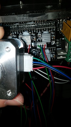
Thanks for your help! I followed the corrections you described. I also went into repetier host and found that the travel and z-axis feed rates were set way too low. Now when I click up on Z it moves up better. I'm still having issues with it homing in the correct directions though. I'm beginning to investigate the wiring. The steppers i'm using have 6 pins. I'm using the harness that came with the sainsmart kit and you can see how I've got them attached to the board in the attachment. This looks slightly different than what is on the sainsmart site though. i think i'll need to lookup how to identify the pins on the steppers to confirm that the harness is correct. Any thoughts? Thank you all for the help!
|
Re: Delta homing issues December 26, 2015 08:54AM |
Registered: 8 years ago Posts: 28 |
You have the homing direction wrong in your config. You want to home to max. If one motor moves down instead of up, adjust the wiring. You dont want one motor inverted and two not in the firmware. It sounds like you may have some loose pins in the connectors. Make sure they are all firmly seated. They can get pushed out when you connect them and it's hard to notice.
'
'
|
Re: Delta homing issues January 18, 2016 06:51PM |
Registered: 8 years ago Posts: 7 |
Ok, i've made some progress. I decided to start from scratch with marlin. It seems to be working better. I hold the carriage so that all of the end stops are triggered. I let it down just enough so they are all open. I click home and after it finishes i am able to move the towers (through repetier) down and where ever I want. I click home again though and the towers seem to think they are already at home. basically it hums, then each tower moves down a bit one by one. When I click home it should move all towers back up till they hit the end stops (max) correct? Not sure what else is going on here. Any thoughts. Thanks for your help really appreciate it. I can move this to the firmware section if it's better suited for that forum.
Sorry, only registered users may post in this forum.