Delta dimmensions modifying calculation
Posted by tomasbond
|
Delta dimmensions modifying calculation August 08, 2016 09:40AM |
Registered: 7 years ago Posts: 9 |
Hi all! My name is Tomas and im writting from Argentina. Im designing a new delta printer and i would like to know what things i need to know to calculate the frame. If i already have a design and i would like to modify it. Can i change the height without changing arm length?if i change the arm length from 242mm to 300mm, what other frame dimmension should i change to fit correctly? I have read a lot about this, but its confusing and i dont want to make errors. Right now im focusing on Athena (http://www.appropedia.org/Athena_Build_Overview) build. I think this original build frame is going to be small for me so i want to modify (staying on same design). Im thinking about making it some higher (1000mm from original 600, aprox), and getting a bigger printing diameter (max 300mm over arm length). Hope community can help me a little! Thanks a lot! Sorry for poor english 

|
Re: Delta dimmensions modifying calculation August 08, 2016 03:36PM |
Registered: 9 years ago Posts: 483 |
Arm length isn't affected by the tower height.
Nothing needs to change when changing the arm length, but that doesn't mean you shouldn't change other properties. It's pretty easy to model the changes using 2d CAD. Model the arms at 20 degrees and at 60 degrees. The 20 degree model will tell you what diameter the build plate needs to be (Don't forget to allow for the effector diameter). The 60 degree model will give you the position of the carriages when the effector is centered.
You will need to make the frame stronger for the added height and width. The linear rails will also need to be larger.
|
Re: Delta dimmensions modifying calculation August 08, 2016 04:26PM |
Registered: 8 years ago Posts: 475 |
For geometry simulation, you can use the OpenScad delta simulator here : [github.com]
You shall read the Wiki page on Delta geometry here : [reprap.org]
The Athena is a rod based printer. For a large printer, you shall increase significantly the rod diameter to maintain reasonable stiffness, which will increase a lot the cost and the carriage weight.
I really feel that rod are not a good solution for large delta printers without using large rod diameter. For the size you want, 12mm may be the minimum.
You can find large rod-based printer, as by example the delta built by AussiePhil but he use 25mm diameter rods...
Edited 1 time(s). Last edit at 08/08/2016 04:29PM by PRZ.
Pierre
- Safety [reprap.org]
- Embedded help system for Duet and RepRap Firmware [forums.reprap.org]
- Enclosed delta printers Lily [rouzeau.net] and Lily Big [rouzeau.net]
- OpenScad delta printer simulator [github.com]
- 3D printing on my site [www.rouzeau.net]
|
Re: Delta dimmensions modifying calculation August 09, 2016 11:16AM |
Registered: 7 years ago Posts: 9 |
Thanks a lot for your answers! I think ill stay in original size because i already have the 8mm rods  . Another thing you could help me with is, whats better for precission printing? 0.9 degrees stepper motor or 1.8? Both motors i have on mind are (http://www.robotdigg.com/product/241) for 0.9 or (http://www.robotdigg.com/product/206/Nema17+48mm+Stepper+Motor) for 1.8. Whats best for precission movements rather than faster printing. I will be using a Smoothieboard with microstepping if this changes something. Thanks a lot again! Your knowledge is much apreciated!
 . Another thing you could help me with is, whats better for precission printing? 0.9 degrees stepper motor or 1.8? Both motors i have on mind are (http://www.robotdigg.com/product/241) for 0.9 or (http://www.robotdigg.com/product/206/Nema17+48mm+Stepper+Motor) for 1.8. Whats best for precission movements rather than faster printing. I will be using a Smoothieboard with microstepping if this changes something. Thanks a lot again! Your knowledge is much apreciated!
|
Re: Delta dimmensions modifying calculation August 09, 2016 11:59AM |
Registered: 8 years ago Posts: 177 |
Tomas:
With 32bit board just go with 0.9deg steppers, might not be a lot to gain but why not get as much as possible, they will give more precise positioning
PRZ: actually I used 20mm rod at 1600mm long.... I believe 16mm would have been ok at that height, but mine is really a huge printer with just about everything scaled up
|
Re: Delta dimmensions modifying calculation August 09, 2016 06:46PM |
Registered: 10 years ago Posts: 327 |
That looks like a very useful tool, if I knew what numbers to put in it. It could really do with an idiots pictorial guide to the important values, to help people like me.
What exactly is beam_int_radius?
Is there anything else that needs changing if I am using Traxxas joints?
Quote
PRZ
For geometry simulation, you can use the OpenScad delta simulator here : [github.com]
You shall read the Wiki page on Delta geometry here : [reprap.org]
I have read it, several times but it still hasn't sunk in.

Regards,
Les
Pointy's Things
Pointy's Blog
|
Re: Delta dimmensions modifying calculation August 10, 2016 09:15PM |
Registered: 7 years ago Posts: 9 |
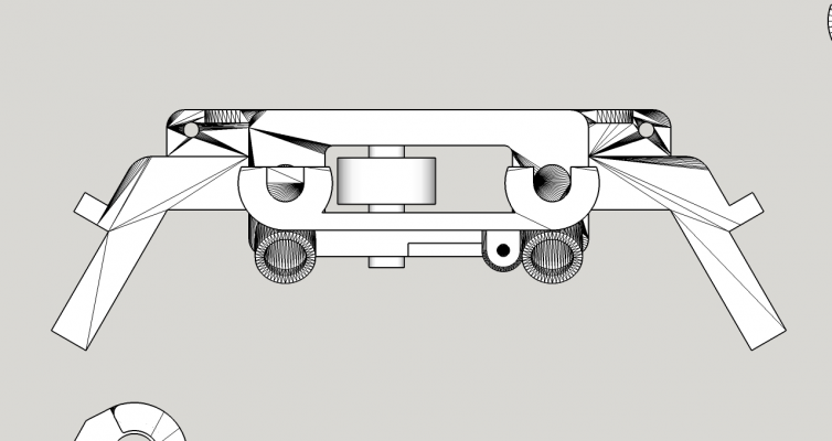
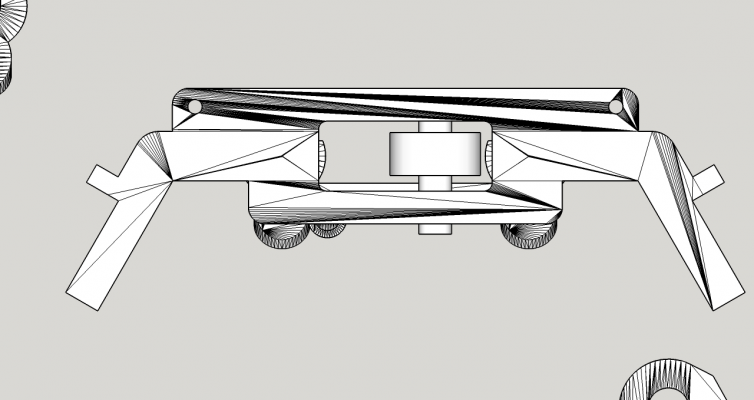
Another question, im desiging and modyfing some pieces for my delta build. I have come to this problem, when im trying to calculate how the belt will be moving i saw this and thought it is a problem, when belt moves in this small place, wouldnt it touch the carriage? or make some friction? Srry for poor english, what do you think? will it work? this are the original stl with the addition of the "bearing 608zz" on the idler end. The image is from top with no perspective. I have bought a GT2 20tooth pulley with bearing to modify the original build and replace this 608zz with this one, need to modify the screw inside from 8mm diameter to one of 5mm for the pulley bore. Will it work? What do you think? Should i change something more for this to work?
Pulley with bearing(for idler): [www.robotdigg.com]
Motor pulley (for motor): [www.robotdigg.com]
Pulley with bearing(for idler): [www.robotdigg.com]
Motor pulley (for motor): [www.robotdigg.com]
|
Re: Delta dimmensions modifying calculation August 10, 2016 09:41PM |
Registered: 7 years ago Posts: 9 |
|
Re: Delta dimmensions modifying calculation August 11, 2016 02:50PM |
Registered: 9 years ago Posts: 483 |
Sorry, only registered users may post in this forum.

