Large Kossel all metal delta build log
Posted by DjDemonD
|
Re: Large Kossel all metal delta build log September 11, 2016 08:45AM |
Registered: 9 years ago Posts: 54 |
|
Re: Large Kossel all metal delta build log September 11, 2016 08:56AM |
Registered: 8 years ago Posts: 3,525 |
The wiring from the bed heater is what was supplied moulded to it and the other supply wires are stripped from a 5A cloverleaf mains cable (as I also needed another c5 plug for the psu as I'm going to use the supplied cable as the cable for the printer itself). 5A @ 240v is 1200w. My bed heater is 500w and my psu is 120w so I'll keep and eye on it when I power it up and check the cables don't get hot. But I think I've got a bit of safety margin.
Edited 1 time(s). Last edit at 09/11/2016 09:45AM by DjDemonD.
Simon Khoury
Co-founder of [www.precisionpiezo.co.uk] Accurate, repeatable, versatile Z-Probes
Published:Inventions
Edited 1 time(s). Last edit at 09/11/2016 09:45AM by DjDemonD.
Simon Khoury
Co-founder of [www.precisionpiezo.co.uk] Accurate, repeatable, versatile Z-Probes
Published:Inventions
|
Re: Large Kossel all metal delta build log September 11, 2016 05:02PM |
Registered: 8 years ago Posts: 3,525 |
Made a little tweak to the effector on BramV's advice posted details here [forums.reprap.org]
Glad it was pointed out that not all of the magnets are properly pressed into the effector, which would have resulted in rods being effectively not equal length.
Simon Khoury
Co-founder of [www.precisionpiezo.co.uk] Accurate, repeatable, versatile Z-Probes
Published:Inventions
Glad it was pointed out that not all of the magnets are properly pressed into the effector, which would have resulted in rods being effectively not equal length.
Simon Khoury
Co-founder of [www.precisionpiezo.co.uk] Accurate, repeatable, versatile Z-Probes
Published:Inventions
|
Re: Large Kossel all metal delta build log September 13, 2016 05:36AM |
Registered: 10 years ago Posts: 14,672 |
Looking good! Regarding cable restraints for the 240V cable to the bed heater, I drilled two pairs of holes in the aluminium base plate and then put zip ties through them to secure the cable.
Large delta printer [miscsolutions.wordpress.com], E3D tool changer, Robotdigg SCARA printer, Crane Quad and Ormerod
Disclosure: I design Duet electronics and work on RepRapFirmware, [duet3d.com].
Large delta printer [miscsolutions.wordpress.com], E3D tool changer, Robotdigg SCARA printer, Crane Quad and Ormerod
Disclosure: I design Duet electronics and work on RepRapFirmware, [duet3d.com].
|
Re: Large Kossel all metal delta build log September 13, 2016 10:41AM |
Registered: 8 years ago Posts: 3,525 |
That's a good idea. Should have my duetwifi by the time I get home (I am away for a couple of days), I can start on the fun part and get it working.
Was thinking about a thermal fuse on the bed heater maybe the maplin 157 deg C type. I would crimp it on in series with one of the AC leads to the bed heater, protect the leads with heatshrink and place it under the silicone heater at the edge? Or is there a better way?
I presume to use one on the hot end it would have to be more like 300 deg C and be attached to the heater block? I'm not sure this one is as useful as the bed heater.
Simon Khoury
Co-founder of [www.precisionpiezo.co.uk] Accurate, repeatable, versatile Z-Probes
Published:Inventions
|
Re: Large Kossel all metal delta build log September 13, 2016 01:36PM |
Registered: 12 years ago Posts: 548 |
Quote
DjDemonD
Was thinking about a thermal fuse on the bed heater maybe the maplin 157 deg C type. I would crimp it on in series with one of the AC leads to the bed heater, protect the leads with heatshrink and place it under the silicone heater at the edge? Or is there a better way?
I presume to use one on the hot end it would have to be more like 300 deg C and be attached to the heater block? I'm not sure this one is as useful as the bed heater.
I put the thermal fuse in about the center of the silicon heater and use kapton tape to hold & insulate the bare wires.
AFAIK, they don't make a thermal fuse with a high enough temperature for a hotend.
|
Re: Large Kossel all metal delta build log September 15, 2016 04:48AM |
Registered: 8 years ago Posts: 3,525 |
There seems to be a 280 deg C thermal fuse from atcsemitec. Looks small enough to be mounted on a heater block. PEPI-H8-thermal-fuses.pdf
That being said the thermal runaway risk is greater with a mains heated bed and ssr.
Edited 1 time(s). Last edit at 09/15/2016 04:50AM by DjDemonD.
Simon Khoury
Co-founder of [www.precisionpiezo.co.uk] Accurate, repeatable, versatile Z-Probes
Published:Inventions
That being said the thermal runaway risk is greater with a mains heated bed and ssr.
Edited 1 time(s). Last edit at 09/15/2016 04:50AM by DjDemonD.
Simon Khoury
Co-founder of [www.precisionpiezo.co.uk] Accurate, repeatable, versatile Z-Probes
Published:Inventions
|
Re: Large Kossel all metal delta build log September 16, 2016 07:47PM |
Registered: 8 years ago Posts: 3,525 |
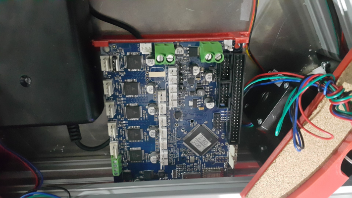
So got the duetwifi card and paneldue controller.
Nicely made card, everything well thought out. They did miss my order but once I contacted them they couldn't apologise enough and sent one out special delivery.
Decided I'd need a back support for it, so I downloaded DC42's version from Thingiverse. I cut away the fan support as I would not quite have enough room in my electronics compartment (and I have two substantial fans).
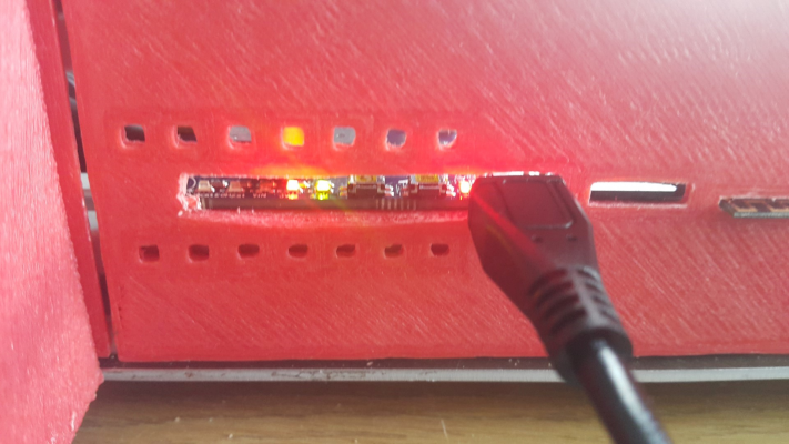
I did run into one immediate problem once I installed the duetwifi, attached a usb cable and powered it up. It showed as the wrong device in windows, it showed as "bossa port" which means it had been erased. The duet wiki explained what to do, its a bit like flashing the firmware on an 8 bit arduino. I did this but still no joy. It was then I realised the front panel I had remixed from DC42's version was pressing the erase and reset buttons as I inserted the usb cable. So I cut away a bunch of this panel, which actually makes the LED's easier to see and the USB port easier to access and protects the erase/reset buttons from accidentally being pushed. I will modify the front panel when I upload all the custom made parts to thingiverse.
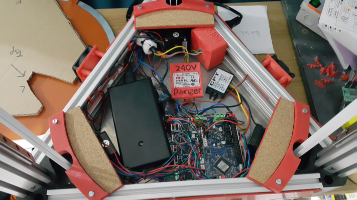
A great many hours spent wiring it all up. Wired the two 12v electronics fans in series so they work on 24v. Did the same with the two print cooling fans. The hotend fan runs off a small adjustable step down module (which is seen wrapped in some plastic just to protect it as its a bit more delicate than most of the electronics). The hot end heater runs via a 24-12v converter. This is wired as follows. On the converter the 24v input is attached to the E0 heater positive on the duetwifi. The ground wire is attached to the main power negative (so essentially the PSU negative) on the duet, then from the converter 12v output to the hot end heater, and back to the duetwifi E0 negative terminal. This means the converter is only powered when the hot end is on, and since the duet wifi applies the PWM to the ground from the hot end heater, I am not sending a PWM signal to the converter input. It works, the thermistor needs some calibration/auto tune.
The bed heats up (no mains voltage nasty surprises). Again thermistor needs tweaking.
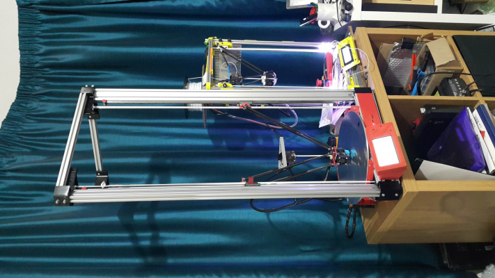
The almost complete machine. The panel due lights up but isn't yet receiving any data, so I've not set something right here, not too worried as the web interface is really good.
Here is a video of some delta autocalibration.
The values after 3 or 4 runs converge nicely so I presume nothing is mechanically amiss. Watch at the end when it brings the head back up at 15000 mm/min travel speed I've never seen a 3d printer move that fast, so very pleased. Apologies for the background noise, my partner was packing stuff. The one slightly sticky hiwin rail seems to be causing no problems so far, and the TMC 2600 stepper drivers interpolating 1/256 microstepping mean you can barely hear the motors at normal speeds.
I need to make a spool holder and then I can see how it prints.
I was reluctant to join the 32 bit revolution but I have to say its a world apart from the old ATmega.
Edited 1 time(s). Last edit at 09/16/2016 07:50PM by DjDemonD.
Simon Khoury
Co-founder of [www.precisionpiezo.co.uk] Accurate, repeatable, versatile Z-Probes
Published:Inventions
|
Re: Large Kossel all metal delta build log September 17, 2016 04:10PM |
Registered: 8 years ago Posts: 3,525 |
So I got the paneldue working by installing the latest firmware update. Decided to use the atmel sam-ba v2.16 software to do so. Fairly easy to do install it select the correct chip its at91sam3s2-ek then connect, find the file and upload it. You can check to see if it matches. Then lock region. Then hit reboot from flash.
Now tuning my thermistors.
Interestingly the B values given in the duet wiki work better than the b value in the datasheet for the thermistor (Semitec 100kOhm NTC Thermistor. (104GT-2) when compared wit temperatures from a k-type thermocouple and multimeter.
Edited 1 time(s). Last edit at 09/19/2016 11:47AM by DjDemonD.
Simon Khoury
Co-founder of [www.precisionpiezo.co.uk] Accurate, repeatable, versatile Z-Probes
Published:Inventions
|
Re: Large Kossel all metal delta build log September 17, 2016 04:23PM |
Registered: 8 years ago Posts: 3,525 |
I have uploaded the STL's for the parts used/made/remixed to make this machine.
[www.thingiverse.com]
Simon Khoury
Co-founder of [www.precisionpiezo.co.uk] Accurate, repeatable, versatile Z-Probes
Published:Inventions
[www.thingiverse.com]
Simon Khoury
Co-founder of [www.precisionpiezo.co.uk] Accurate, repeatable, versatile Z-Probes
Published:Inventions
|
Re: Large Kossel all metal delta build log September 18, 2016 07:04AM |
Registered: 8 years ago Posts: 3,525 |
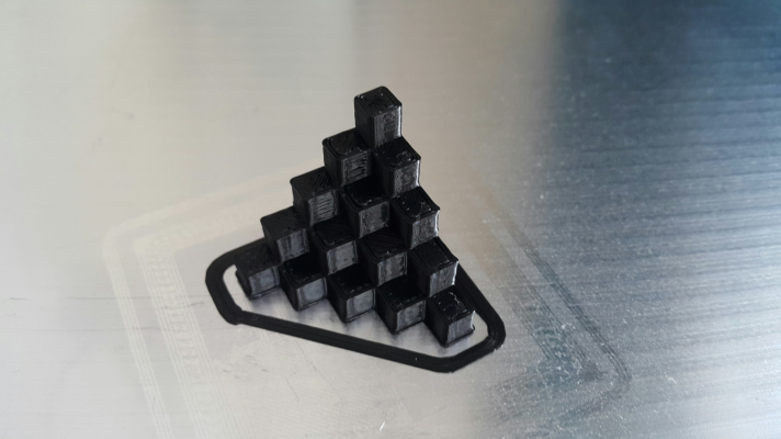
This is the 3rd object it has printed. So well pleased.
Next to see how fast it can print this object without losing quality.
A couple of observations:
The 120w laptop supply seems quite up to the job as the bed is not powered by it.
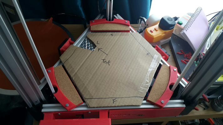
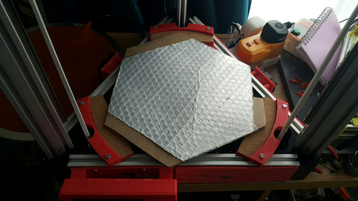
The electronics compartment is not too hot in use, (35 deg c) but between the bed and the electronics I placed a thick double ply cardboard top (the metal panel I intended to use didn't really fit) and lined the underside of it with foil bubble wrap. You have to cut away a section under the bed heater where the wiring is connected.
The 12v step down converter does not get hot, neither does the ssr. They are both running well below their rated capacity. (3A on 12v converter, 5A rated; 2A on the ssr, 25A rated).
Will add some LEDs, probably use 2 x 12v strips in series. I find these strip LEDs get hot so mounting them on the frame helps dissipate this heat. Also I tend to put them on the front two towers facing inwards so they aren't shining in my face.
Edited 3 time(s). Last edit at 09/18/2016 11:27AM by DjDemonD.
Simon Khoury
Co-founder of [www.precisionpiezo.co.uk] Accurate, repeatable, versatile Z-Probes
Published:Inventions
|
Re: Large Kossel all metal delta build log September 20, 2016 04:13AM |
Registered: 8 years ago Posts: 3,525 |
So yesterday the inevitable issues started appearing, it had all been going rather too well.
I tried the babystepping workaround being discussed on Duet forum, but all that seemed to happen whether I went up or down was a nozzle crash. Not a big problem as I was fairly happy with my nozzle to bed clearance and it was printing reasonably well, I was just testing the idea out.
Then one of the magnets came loose from the effector, probably due to the head crashes.
I rebonded it.
I think this is to do with having an offset in the slicer. Will try again later on.
Then I decided to try a bed level test spiral and realised that even with auto-calibration having arrived at a fairly consistent solution, the level by the x tower is way lower than by the y tower.
So checking all the magnets again, maybe a drizzle of superglue in/around them.
Then seeing if its my bed being physically not level or incorrect endstop adjustments creating a false plane.
Also wondering if the the firmware can do auto bed levelling and whether I ought to try it.
Edited 1 time(s). Last edit at 09/20/2016 06:37AM by DjDemonD.
Simon Khoury
Co-founder of [www.precisionpiezo.co.uk] Accurate, repeatable, versatile Z-Probes
Published:Inventions
|
Re: Large Kossel all metal delta build log September 20, 2016 07:02PM |
Registered: 8 years ago Posts: 3,525 |
Okay so plenty to write about. The tuning and tweaking continues.
The babystepping trick now works using G92 Z0.425 (down) or G92 Z0.375 (up), (assuming a 0.4mm first layer with no slicer offset). This can be sent using a macro from the paneldue controller or via the gcode console. Count the number of times the correction is sent until you have a good first layer and then you can enter that as a M206 offset in the config.g for next time. It only works for the first layer as its absolute not relative.
The bed level was wrong as the bed.g file was incorrect.
My probing points assumed the nozzle is at the coordinates to be probed, whereas what matters are the coordinates that position the probe at each necessary point, since the firmware is not doing auto bed levelling it is unimportant if the probe has an offset from the nozzle. What's important is that the probe measures the bases of the towers, the mid points between them and some other points closer towards the centre, then the centre itself (the probe over the centre). Assuming no effector tilt, and I haven't seen any evidence of it so far it can then calculate all the 7 factors properly and the deviations reported back get lower and lower, currently at 0.052 from around 0.3 when I started.
My bed.g looks like this (assuming an IR probe and a bed diameter of 330mm)
I have added G32 to my start gcode to do this auto-calibration before each print.
I also wrote a second short bed file to check the bed level at the base of each of the three towers and output the heights, so long as these are all reasonably small differences from the expected height objects should print evenly across the bed.
This presumes the printer is homed. I added this after G32 in the start gcode (use M98 Pbedcheck.g - where the file is called bedcheck.g) for a quick bed level confirmation before each print. It does this whilst pre-heating the extruder, so there is time to abort the print if these values are way off.
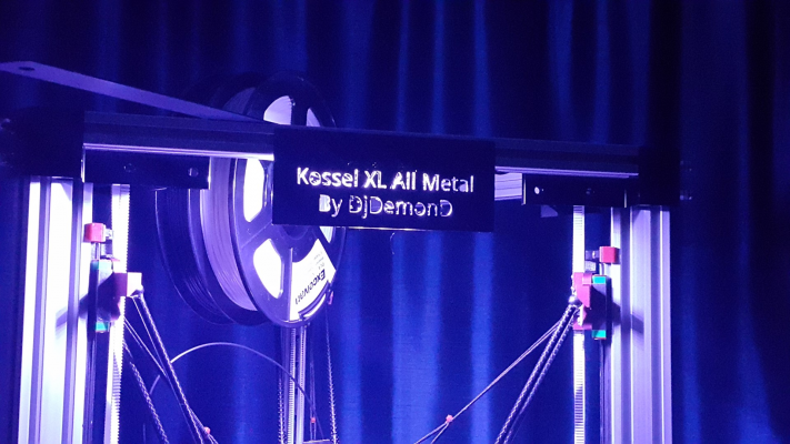
Now printing a name plate to put on the front of the machine at the top, in front of where I have placed an LED strip (two equal sets of 12v LEDs are connected in series to give 24v) which is connected to the P1 fan output, and therefore can be dimmed or turned on or off using gcode from the console, or even flashed at the end of a print etc... Childish but why not.
Edited 4 time(s). Last edit at 09/21/2016 02:35PM by DjDemonD.
Simon Khoury
Co-founder of [www.precisionpiezo.co.uk] Accurate, repeatable, versatile Z-Probes
Published:Inventions
The babystepping trick now works using G92 Z0.425 (down) or G92 Z0.375 (up), (assuming a 0.4mm first layer with no slicer offset). This can be sent using a macro from the paneldue controller or via the gcode console. Count the number of times the correction is sent until you have a good first layer and then you can enter that as a M206 offset in the config.g for next time. It only works for the first layer as its absolute not relative.
The bed level was wrong as the bed.g file was incorrect.
My probing points assumed the nozzle is at the coordinates to be probed, whereas what matters are the coordinates that position the probe at each necessary point, since the firmware is not doing auto bed levelling it is unimportant if the probe has an offset from the nozzle. What's important is that the probe measures the bases of the towers, the mid points between them and some other points closer towards the centre, then the centre itself (the probe over the centre). Assuming no effector tilt, and I haven't seen any evidence of it so far it can then calculate all the 7 factors properly and the deviations reported back get lower and lower, currently at 0.052 from around 0.3 when I started.
My bed.g looks like this (assuming an IR probe and a bed diameter of 330mm)
; Auto calibration routine for delta printers

M561					; clear any bed transform, otherwise homing may be at the wrong height
G31 X0 Y0				; don't want any probe offset for this
G28					; home the printer
G28					;home again in case of endstop problem

; Probe the bed and do 6- or 7-factor auto calibration positions are probe positions (x-13,y34)
G30 P0 	X-87 	Y-86 	Z-99999		; X tower
G30 P1 	X13 	Y-140 	Z-99999		; XY point
G30 P2 	X104 	Y-90 	Z-99999		; Y tower
G30 P3 	X130 	Y16 	Z-99999		; YZ point
G30 P4 	X13 	Y100 	Z-99999		; Z tower
G30 P5 	X-100 	Y40 	Z-99999		; YZ point
G30 P6 	X-50 	Y-60 	Z-99999		; X tower middle
G30 P7 	X0 	Y-100 	Z-99999		; between X and Y towers middle
G30 P8 	X80 	Y-70 	Z-99999		; Y tower middle
G30 P9 	X80 	Y-10 	Z-99999		; between Y and Z towers middle
G30 P10 X13 	Y60 	Z-99999		; Z tower middle
G30 P11 X-57 	Y054 	Z-99999		; between Z and X towers middle
G30 P12 X-27 	Y-64    Z-99999		; X tower inner
G30 P13 X53 	Y-64    Z-99999		; Y tower inner
G30 P14 X13 	Y6   	Z-99999		; Z tower inner
G30 P15 X13 	Y-34 	Z-99999 S7	; centre, and auto-calibrate 7 factors

G1 X0 Y0 Z150 F10000			; get the head out of the way of the bed
I have added G32 to my start gcode to do this auto-calibration before each print.
I also wrote a second short bed file to check the bed level at the base of each of the three towers and output the heights, so long as these are all reasonably small differences from the expected height objects should print evenly across the bed.
;bed level check

G30 P0 X-100 Y-60 Z-99999		; X tower
G30 P1 X100 Y-60 Z-99999		; Y tower
G30 P2 X0 Y100 Z-99999	S-1		; Z tower

G1 X0 Y0 Z100 F10000
This presumes the printer is homed. I added this after G32 in the start gcode (use M98 Pbedcheck.g - where the file is called bedcheck.g) for a quick bed level confirmation before each print. It does this whilst pre-heating the extruder, so there is time to abort the print if these values are way off.
Now printing a name plate to put on the front of the machine at the top, in front of where I have placed an LED strip (two equal sets of 12v LEDs are connected in series to give 24v) which is connected to the P1 fan output, and therefore can be dimmed or turned on or off using gcode from the console, or even flashed at the end of a print etc... Childish but why not.
Edited 4 time(s). Last edit at 09/21/2016 02:35PM by DjDemonD.
Simon Khoury
Co-founder of [www.precisionpiezo.co.uk] Accurate, repeatable, versatile Z-Probes
Published:Inventions
|
Re: Large Kossel all metal delta build log September 21, 2016 05:23AM |
Registered: 10 years ago Posts: 14,672 |
Sounds good! In the next firmware release I will implement relative G92 commands to make baby stepping easier.
Edited 1 time(s). Last edit at 09/21/2016 05:24AM by dc42.
Large delta printer [miscsolutions.wordpress.com], E3D tool changer, Robotdigg SCARA printer, Crane Quad and Ormerod
Disclosure: I design Duet electronics and work on RepRapFirmware, [duet3d.com].
Edited 1 time(s). Last edit at 09/21/2016 05:24AM by dc42.
Large delta printer [miscsolutions.wordpress.com], E3D tool changer, Robotdigg SCARA printer, Crane Quad and Ormerod
Disclosure: I design Duet electronics and work on RepRapFirmware, [duet3d.com].
|
Re: Large Kossel all metal delta build log September 21, 2016 01:49PM |
Registered: 8 years ago Posts: 3,525 |
That would be good. Having macros available either from web interface or on the paneldue allows for enormous flexibility, which I am only just starting to explore.
Simon Khoury
Co-founder of [www.precisionpiezo.co.uk] Accurate, repeatable, versatile Z-Probes
Published:Inventions
Simon Khoury
Co-founder of [www.precisionpiezo.co.uk] Accurate, repeatable, versatile Z-Probes
Published:Inventions
|
Re: Large Kossel all metal delta build log September 21, 2016 02:42PM |
Registered: 9 years ago Posts: 1,159 |
Have printed out the Flying extruder parts must say I wondered why they had all the cutouts and holes etc then when it came off the bed (Well whilst it was still printing actually) that it is effectively a scale model of the upper frame (Or maybe the Lower one). Looks very nice and will re-do the carriage pieces to fit my Robotdigg one and get it mounted soon and see the Difference?
Doug
Doug
|
Re: Large Kossel all metal delta build log September 21, 2016 02:50PM |
Registered: 8 years ago Posts: 3,525 |
Cool yeah my Kossel Mini flying extruder which is on thingiverse was a much more arbitrary design. When I sat down to make one for this printer I realised I was looking at a model of the printer on the screen, so why not have a little fun.
Love to see yours and hear more about it.
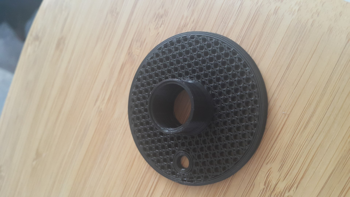
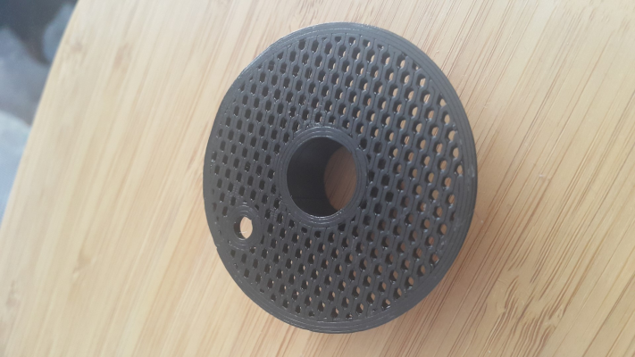
Couple of prints that I did earlier attempting to replicate this very impressive 3D printed fly fishing reel, I like a challenge.
Simon Khoury
Co-founder of [www.precisionpiezo.co.uk] Accurate, repeatable, versatile Z-Probes
Published:Inventions
Love to see yours and hear more about it.
Couple of prints that I did earlier attempting to replicate this very impressive 3D printed fly fishing reel, I like a challenge.
Simon Khoury
Co-founder of [www.precisionpiezo.co.uk] Accurate, repeatable, versatile Z-Probes
Published:Inventions
|
Re: Large Kossel all metal delta build log September 22, 2016 04:56AM |
Registered: 8 years ago Posts: 3,525 |
So today's issue is bed level. It should be level in that the bed supports sit on the frame, they are all identical and the frame is accurate. The bed is tooling plate.
However I am measuring the level using my IR z probe, and this level is relative to the endstops.
Auto-calibration is giving me deviation values as low as 0.04, so I am lead to believe this is very good. But when I check bed level there is up to 0.1mm difference from one tower to the next. This is making a difference to printing, the nozzle is grinding one side and "flying high" above the bed on the other.
One thing that is strange, after auto-calibration, and bed level checking, I can add some paper shims between the bed supports and the bed, and manually level it. When I do the level test I get very close readings at each tower. But when I auto-calibrate again with the manually levelled bed, the level goes out of whack afterwards.
So I began to suspect the endstops might be loose or moving slightly. It does appear that the opto-flags I'm using whilst large, black and very good at getting a good trigger, are maybe rubbing slightly on the endstops. So I filed them down a bit. By this point it was late and I was tired, so I will have to wait until this evening to see if it helped.
Here's a question for the experts.... Should I be trying to physically position my endstops all at the same height relative to the bed? Or to the frame? Or does it not matter as their positions can be (and are) compensated for in software anyway?
I also wonder if my measuring device (IR sensor) is getting a reliable reading. At present I'm waiting on a sheet of print bite, so I am currently using hairspray onto the aluminium plate. This creates areas on the bed of differing appearance optically, are these also likely to be areas of differing IR reflection? Is it valid to test this by moving the sensor around and seeing if the analogue value changes (this could be just height related)??
Simon Khoury
Co-founder of [www.precisionpiezo.co.uk] Accurate, repeatable, versatile Z-Probes
Published:Inventions
|
Re: Large Kossel all metal delta build log September 22, 2016 07:57AM |
Registered: 10 years ago Posts: 14,672 |
It's possibly that the sensor is triggering at different heights due to variations on the surface - especially if the sensor is saturating and giving a reading of around 1000 when triggered instead of around 535. However, it's also possible that your effector is tilting slightly as it moves in the XY plane. This causes the relative heights of the sensor and the nozzle to change. You can verify this by lowering the nozzle so it just touches the bed, then using feeler gauges to measure the gap between the bed and the bottom edge of the sensor board. Repeat at different XY positions.
If effector tilt is the problem, the best solution is to fix whatever geometrical error is causing the tilt. The alternative is to measure the sensor trigger height at each probe point and correct for the variation using the H parameter on each G30 command in the bed.g file.
HTH David
Large delta printer [miscsolutions.wordpress.com], E3D tool changer, Robotdigg SCARA printer, Crane Quad and Ormerod
Disclosure: I design Duet electronics and work on RepRapFirmware, [duet3d.com].
|
Re: Large Kossel all metal delta build log September 22, 2016 08:41AM |
Registered: 8 years ago Posts: 3,525 |
No the sensor triggers at 535 everywhere, so I'm glad we can rule that one out.
I will check for effector tilt, I didn't think I had any but I've only been using circular spirit levels so far to check and I suspect they're nowhere near accurate enough. Thanks.
Simon Khoury
Co-founder of [www.precisionpiezo.co.uk] Accurate, repeatable, versatile Z-Probes
Published:Inventions
I will check for effector tilt, I didn't think I had any but I've only been using circular spirit levels so far to check and I suspect they're nowhere near accurate enough. Thanks.
Simon Khoury
Co-founder of [www.precisionpiezo.co.uk] Accurate, repeatable, versatile Z-Probes
Published:Inventions
|
Re: Large Kossel all metal delta build log September 22, 2016 03:01PM |
Registered: 8 years ago Posts: 117 |
As a matter of fact, I was using a glass plate with hairspray coat on it at the beginning, and I can confirm, that trigger height for the IR probe was dependending on the coat thicknes and presence. So if you cover only a part of the bed this will mess up the calibration a lot. The same goes for the glue-stick, tapes, etc.
PrintBite is definitely a better solution, I have been using it for months now - very happy. Probably the best upgrade to the printer.
Nevertheless it is worth checking for effector tilt, and/or using a trigger height offset in the bed.g file.
Speaking of which, David, I got an imression, that if I measure the nozzle and trigger heights very precisely using gauges, it looks like I do not get the best first layer appearance. For instance, if the measured trigger height is 2.45mm, I get some overextrusion on the first layer, and if I set the config.g to use 2.35mm - first layer looks just perfect.
Can it be, that software (slicers, or whatever) supposes that there is a 'sheet of paper' gap between the nozzle and the bed when the firmware reports Z=0mm?
Or to ask it slightly differently, if I use the paper as a gauge to touch-up the bed, should I tell the FW I am at zero, or at the thickness of this paper sheet?
Sorry for chiming in with a slight off-topic...
|
Re: Large Kossel all metal delta build log September 22, 2016 03:24PM |
Registered: 8 years ago Posts: 3,525 |
I will try the calibration with a clean bed. And I'm printing Nebbians effector tilt meter on the other printer.
Teilchen - No worries its a good question. I use printbite on my other two printers I wouldn't use anything else.
Edited 4 time(s). Last edit at 09/22/2016 03:27PM by DjDemonD.
Simon Khoury
Co-founder of [www.precisionpiezo.co.uk] Accurate, repeatable, versatile Z-Probes
Published:Inventions
Teilchen - No worries its a good question. I use printbite on my other two printers I wouldn't use anything else.
Edited 4 time(s). Last edit at 09/22/2016 03:27PM by DjDemonD.
Simon Khoury
Co-founder of [www.precisionpiezo.co.uk] Accurate, repeatable, versatile Z-Probes
Published:Inventions
|
Re: Large Kossel all metal delta build log September 22, 2016 04:09PM |
Registered: 9 years ago Posts: 1,159 |
Quote
dougal1957
Have printed out the Flying extruder parts must say I wondered why they had all the cutouts and holes etc then when it came off the bed (Well whilst it was still printing actually) that it is effectively a scale model of the upper frame (Or maybe the Lower one). Looks very nice and will re-do the carriage pieces to fit my Robotdigg one and get it mounted soon and see the Difference?
Doug
Right the new Stepper arrived (a 20mm long Pancake from OMC-Stepper) and it woulnd't fit your mount. (A Dremel solved it thank god I printed it with 100% infill)
there was insufficient clearance around the lower screws on the motor you may want to increase it a little (If looking from the Bed side it is the furthest Right hand screw with the Motor at the top hope that makes sense)
Doug
|
Re: Large Kossel all metal delta build log September 22, 2016 04:11PM |
Registered: 8 years ago Posts: 3,525 |
Yes there was, I recall, a little adjusting required.
Edited 1 time(s). Last edit at 09/22/2016 06:44PM by DjDemonD.
Simon Khoury
Co-founder of [www.precisionpiezo.co.uk] Accurate, repeatable, versatile Z-Probes
Published:Inventions
Edited 1 time(s). Last edit at 09/22/2016 06:44PM by DjDemonD.
Simon Khoury
Co-founder of [www.precisionpiezo.co.uk] Accurate, repeatable, versatile Z-Probes
Published:Inventions
|
Re: Large Kossel all metal delta build log September 22, 2016 07:23PM |
Registered: 8 years ago Posts: 3,525 |
So having hairspray on the aluminium definitely gives very different height readings with the IR probe. A clean bed (or the printbite when it arrives, will help).
If there is effector tilt its very small. I can get reasonably good bed level after calibration. There is around 0.5mm from one tower base to the next of height difference after calibration over 300mm.
Going back to 6 factor calibration from 7 seems to help with consistency, I am using the mean of the diagonal rod lengths that it previously suggested. My printer isnt quite able to get the rods horizontal to make this calculation more accurate.
I am going to try a modified fan shroud which will place the sensor much closer to the nozzle thereby reducing the effect of any slight tilt I have, and reducing the overall size of the head.
Also I am finding occasionally at coordinates near to the bed edges the magnets detach from the effector with the expected dramatic results. At less extreme positions they are working. Longer arms might help. I wonder if adding some neodymium disc magnets might strengthen them without going as far as BramV did and replacing them all with stronger ones, and having to press/glue 12 magnets into place.
Edited 3 time(s). Last edit at 09/23/2016 05:04AM by DjDemonD.
Simon Khoury
Co-founder of [www.precisionpiezo.co.uk] Accurate, repeatable, versatile Z-Probes
Published:Inventions
|
Re: Large Kossel all metal delta build log September 26, 2016 06:38PM |
Registered: 8 years ago Posts: 3,525 |
Okay so I got 25 very strong neodymium magnets 12mm diameter 2mm thick. So strong when stacked together I pulled one off the pile and it snapped back into the rest and shattered. Luckily I needed 24.
I've added two each of these to the existing magnets at the effector and carriages, to strengthen them without having to replace the magnets and it does help. However the balls were still becoming detached. I reduced accelerations to 800. But this didn't help, it was then I noticed that it was when the effector came to a stop the balls came away from the magnets. So I looked at the jerk values which were 1000, so I presume this means the firmware is not decelerating as the speed is below the jerk value so it's coming to an abrupt halt. So I reduced these to 300mm/min (5mm/s) and the balls now remain attached - mostly. What effect this has on printing I don't know, but its at the extreme ranges that it happens, so maybe I can just add some gcode to my bed.g file to slow the machine right down for calibration then speed it back up to print which will be mainly in the middle of the bed where the arm's angle to the effector is less obtuse, this is when the balls mainly come away from the magnets.
To help further I tested having a longer bowden tube to the flying extruder and therefore having less elastic force pulling the effector towards the carriages, this seemed to make it worse, now I have a shorter bowden tube and it seems to be better.
I have made a new fan shroud V6MSX-shroudwithIRsensormount_fixed.stl & V6MSX-fanduct.stl which mounts the IR sensor very close to the nozzle to minimise effector tilt affecting the sensor trigger height from one position in xy to another. I wrapped the sensor in kapton, and the heater block has a silicone cover so the sensor should stay cool enough in use (yet to be seen).
Autocalibration now results in a deviation of 0.040mm the lowest I've seen it report. However bed level still seems off, and its inconsistent, some readings of bed level over repeated runs yield differences in bed height up to 0.1mm from one run to the next, so I am now thinking the aluminium surface is too reflective, even though the sensor analogue reading is not 1000+ as DC42 suggested it might be if the sensor was saturating. I am waiting on printbite, which is much more evenly IR reflective. So for now at a standstill again.
Edited 2 time(s). Last edit at 09/27/2016 07:08AM by DjDemonD.
Simon Khoury
Co-founder of [www.precisionpiezo.co.uk] Accurate, repeatable, versatile Z-Probes
Published:Inventions
|
Re: Large Kossel all metal delta build log September 27, 2016 04:12AM |
Registered: 8 years ago Posts: 916 |
Man that must be frustrating. I can see that you've pulled out all the stops to try to get a perfect machine right from the start, and for it to have those sorts of issues must be quite annoying.
If it helps any, I've had a lot of success with this Z sensor, which is immune to issues with reflectivity and effector tilt. If you have a spare optical endstop and servo lying around then it might be worth a try.
[www.thingiverse.com]
If it helps any, I've had a lot of success with this Z sensor, which is immune to issues with reflectivity and effector tilt. If you have a spare optical endstop and servo lying around then it might be worth a try.
[www.thingiverse.com]
|
Re: Large Kossel all metal delta build log September 27, 2016 06:12AM |
Registered: 8 years ago Posts: 3,525 |
Thanks, but I was under no illusions with this machine that it would be anything but difficult. Law of diminishing returns isn't it. Tempted to switch to regular arms but I like the zero backlash on the magnets.
A lot of the things I've tried to account for are things you (and a few others) have mentioned that caused problems later on, so I've tried to avoid these issues in the build.
Your sensor looks very well thought out and its a wonderful write up on Thingiverse. I've no experience with servo deployed sensors but I am sure its perfectly doable. I love the idea that the pin slides independently of the servo deployed position, eliminating the inaccuracy of servo probes. You don't really even need the servo, you could just manually enable the probe and then stow it after calibration.
I'm also quite keen to try the piezo discs as well they look quite promising, I've used FSR's on the mini kossel. I feel that the nozzle is still the best probe, especially on a delta. I just need a 100% reliable way of detecting the nozzle touching the bed which works on various printing surfaces. For now I'm going to work through the issues with the IR sensor. I might put a disc of black cardboard on the bed, if I can find one that's really flat, and see if it is the aluminium which is giving inconsistent readings.
Edited 1 time(s). Last edit at 09/27/2016 07:57AM by DjDemonD.
Simon Khoury
Co-founder of [www.precisionpiezo.co.uk] Accurate, repeatable, versatile Z-Probes
Published:Inventions
|
Re: Large Kossel all metal delta build log September 27, 2016 10:36AM |
Registered: 8 years ago Posts: 3,525 |
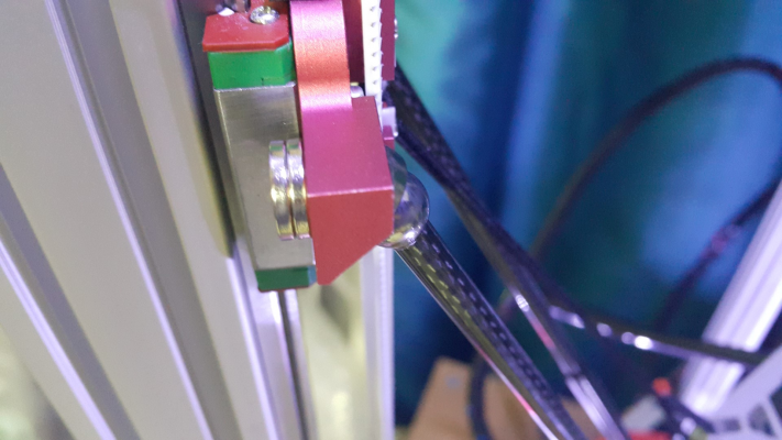
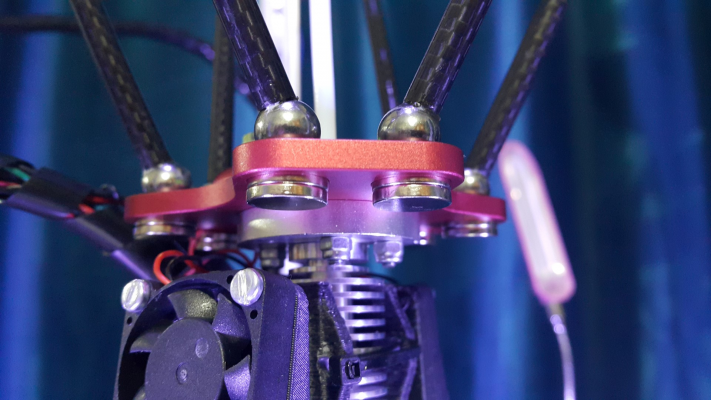
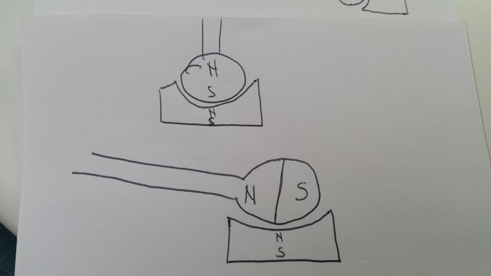
One other issue with this magnet system that might be coming into play here, does this seem logical?
The balls are not magnets, at least until they are attached to the magnets in the carriages, then they will become magnetised.
Since the machine sits at rest with the arms at around 60 degrees to the effector, the balls develop a north and south pole over time. This might be less of an issue if the machine were in continuous use, but it isnt. So when the arms are at a very obtuse angle to the effector the poles are not aligned, there is still attraction to the balls, as they are only weak magnets compared to the magnets themselves, but the attraction is weaker than at the acute angle.
Is this plausible? It seems to chime with the fact that the holding force at obtuse angles seems less now, than it did when I first brought magnet and ball into contact. Maybe the effector needs to rest unattached to the magnets when not in use.
Edited 1 time(s). Last edit at 09/27/2016 10:36AM by DjDemonD.
Simon Khoury
Co-founder of [www.precisionpiezo.co.uk] Accurate, repeatable, versatile Z-Probes
Published:Inventions
|
Re: Large Kossel all metal delta build log September 27, 2016 12:54PM |
Registered: 9 years ago Posts: 1,159 |
Quote
DjDemonD
One other issue with this magnet system that might be coming into play here, does this seem logical?
The balls are not magnets, at least until they are attached to the magnets in the carriages, then they will become magnetised.
[attachment 84295 20160927_144119.jpg]
Since the machine sits at rest with the arms at around 60 degrees to the effector, the balls develop a north and south pole over time. This might be less of an issue if the machine were in continuous use, but it isnt. So when the arms are at a very obtuse angle to the effector the poles are not aligned, there is still attraction to the balls, as they are only weak magnets compared to the magnets themselves, but the attraction is weaker than at the acute angle.
Is this plausible? It seems to chime with the fact that the holding force at obtuse angles seems less now, than it did when I first brought magnet and ball into contact. Maybe the effector needs to rest unattached to the magnets when not in use.
I suspect that you may have something there but I think more important is the fact the the Magnets on the Effector are flat whereas I think them being set at something between 30 and 45 degrees would be better?
Maybe that is why most seem to have the Ball on the Effector and carriages and the Magnets in the rods with Cups as per Hayden's Rods.
Just a couple of thoughts
Doug
Sorry, only registered users may post in this forum.
