Large Kossel all metal delta build log
Posted by DjDemonD
|
Large Kossel all metal delta build log August 22, 2016 05:59PM |
Registered: 8 years ago Posts: 3,525 |
I haven't self sourced a printer before so I thought I'd share my experience building a large kossel delta. Nothing I'm doing is particularly innovative but this log might be helpful for others trying a similar thing and I am certainly going to pick up a good bit of advice along the way.
My requirements are an ABS capable delta printer with a decent build volume roughly 300+mm diameter with no use of printed structural parts. I am not sure I fully subscribe to the thinking that printed parts are bad mkay, but I intend to find out how much an all metal construction improves the print quality.
I'm drawing heavily on DC42's large kossel build for inspiration. As such I opted for the 355mm width extrusions and 1m tall towers. Initially bought 2020 metal aluminium corners from Aliexpress but after reading around, agreed with the idea that 2040 would be a better choice for this size printer.
So I got a set of 2040 aluminium corners (aliexpress) and ordered 9x 355mm 2020 extrusions and 3x 1m 2040 extrusions from Motedis. The current low exchange rate of the pound has made everything around 10% more expensive but I've always previously considered cost before performance so with this machine I am putting quality first.
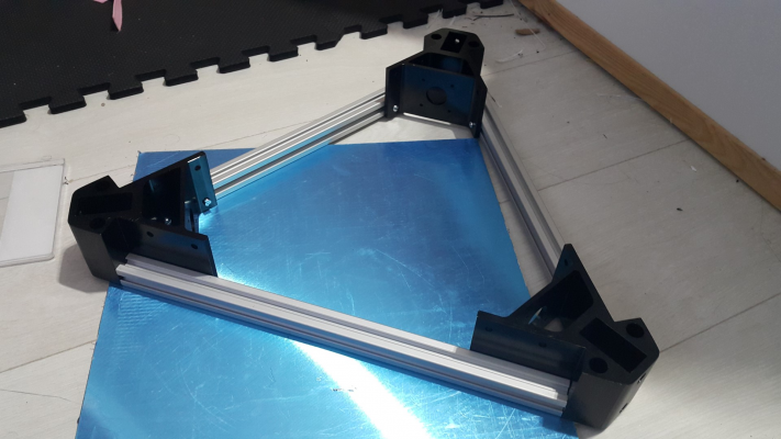
So I started with the base, I bought a 400mmx400mm 5mm thick aluminium tooling plate and it seemed that it was the most likely candidate for a flat surface I have lying around. It will later be cut into a disc to make the build plate. Why not build the frame on it?
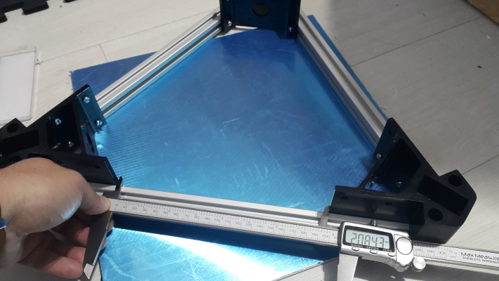
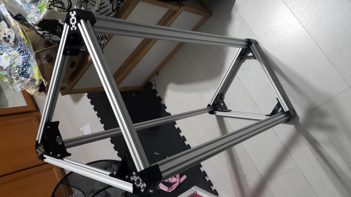
I have attached the 3 horizontal extrusions to the corners measuring the distance between the corners with calipers.
I'm using m4 machine screws and half drop-in t-nuts (eBay). The frame only just fits on the tooling plate.
Once these are attached and all equally spaced, I added the upper set and rechecked the distances to ensure the corners are all equally spaced and nothing had moved.
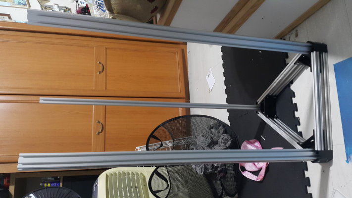
Then the towers, you need to attach the bolts and tnuts loosely before pushing the towers in, I pushed them all in until they were flat on the tooling plate. The towers can move about so I used a set square to ensure they were at 90 deg to the base, before tightening the bolts. The corners I have, have countersunk holes for the bolts to hold the towers, I did not have any countersunk bolts so used some m4 washers to allow the machine screws to sit better.
Apologies this image only wants to display landscape, it will display portrait if clicked-on, excuse the washing basket and general mess.
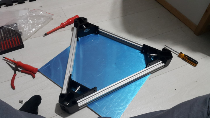
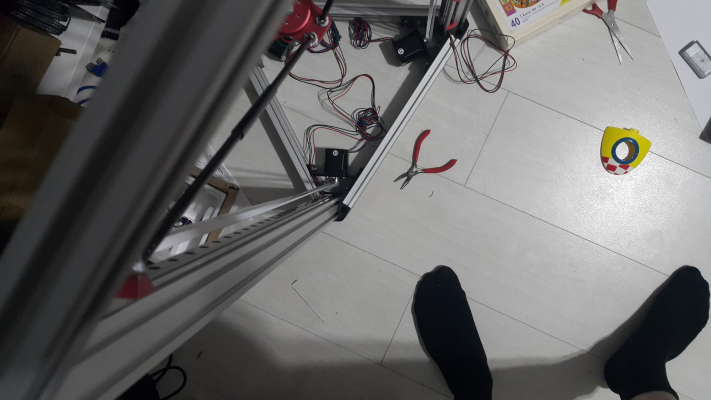
Now for the top section which I built in the same way I built the base, on the tooling plate and with the distances between the corners all equal and the same as for the base. If it's all square then attaching it to the lower part of the frame should be easy, and it was.
This set of corners came with the idler pulleys with bearings so they are attached.
I then rechecked the distances between the towers at the base, and again at the top to ensure they are all the same. Some were a few tens of a millimeter out some loosening of the bolts and applying a little pressure on the frame whilst doing them back up again and they are all within 0.1mm, as I read there is a little elasticity so holding it all together whilst doing up the bolts helped. This should ensure the towers are all equally spaced and vertical.
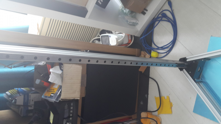
I am using 800mm MGN12H linear guide rails (aliexpress), which fit perfectly and allow full travel of the carriages, although 600mm rails would be long enough to allow the effector, with hot end attached, to reach any part of the bed. I know this now I have built it but was not certain about it at the time. One carriage had some ball bearings missing so I replaced them with some new ones, turns out they are 3/32inch or 2.35mm (I could only find this size in inches). They all required considerable cleaning with automotive brake cleaner to remove the waxy coating put on when they are packaged and liberal application of lithium grease. One was notchy at first but the more I slide it up and down the better it is getting.
I attached them to the towers with m3 machine screws and m3 half drop-in tnuts. One at the top, one in the middle and one at the bottom. To ensure they are all straight with the towers I used calipers set to 4mm to check the alignment top and bottom, to ensure they are all at the same height I placed a 60mm bolt under each rail, did up the top nut after ensuring 4mm each side to the tower extrusion, then the bottom nut, then the middle one, rechecked the alignment and then put some duck tape at the base to stop the carriages sliding off and losing their bearings. I have allowed enough space at the lower end to remove a carriage if needed for maintenance later.
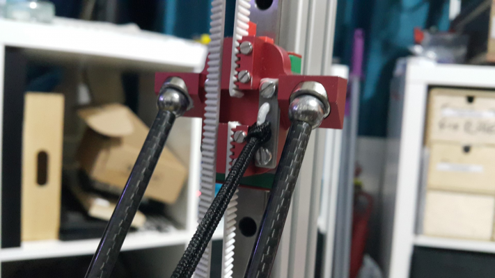
I have decided to use magnetic ball arms and carriages (aliexpress) which have 20mm hole spacing to match the MGN12H rail carriages which are threaded for m3. Whilst the carriages can move about before the bolts are done up I found that by nearly doing up all 4 bolts so they were just slightly loose I was able to jiggle the carriages into place, which then seem to sit naturally in one definite position, which was repeatable on the other two. This seems adequate to ensure that none of them are off centre or twisted relative to the linear rail carriages and therefore the rails and towers. I like the idea that magnetic arms will enable easy removal of the effector and that they will come apart if the effector hits anything, minimising the damage in the event of a crash during testing/printing. I am hoping they do not come undone during normal use (yet to be seen).
The arms were 300mm which seemed a bit short for the bed size I want, and they were not all exactly the same length, so I bought some carbon fibre tubing 6mm ID, cut the 6 arms in the middle, and made a jig with ball recesses set320mm 330mm apart. I glued the pieces of the jig (printed in two parts as I can't print 330mm on my other printers), to a piece of wood. I then used epoxy resin to bond the arms into the tubes, equally spaced by marking the distance each arm needed to be inserted on the base for the jig. I covered the jig in vaseline to ensure I didn't stick the arms to it when gluing them. 5 of them fitted perfectly they have an OD of 5.85mm except one where the arms would not fit into the tube (turns out the tube is slightly undersized at one end) so I reduced the arms OD with an oribtal sander until they fitted into the tube, the carbon fibre regains its shine once the epoxy is applied.
I glued them one at a time, with 5 minute set epoxy, now they are all exactly the same length.
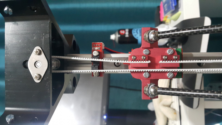
Next I fitted the endstops, I have decided to use optical endstops, mostly as I have not used them before but it stands to reason they should be accurate, reproducible and have good longevity. I am not sure if they will work directly off the Duet Wifi I intend to use to control the machine as it runs on 3.3v but I am going to use a laptop style PSU with a additional USB output so I'll have a 5v rail to use if needed. I printed some opto flags and bonded them to the carriages with superglue, ensuring they sit centrally in the gap in the endstops and reach far enough into the endstop to trigger it with a few millimetres of leeway.
I attached the belts. I am using steel reinforced belt, hard to cut unless you bend the reinforcing metal wires until they fatigue and then cut them, they should be resistant to stretching and the white polyurethane material is very hard wearing. They don't go around very small pulleys (12teeth or less) but I am using 16 tooth pulleys on my motors, so they should be fine. Initially I tried to run them untwisted, with the teeth facing the smooth top idler pulleys, this results in the belts being very tight against the carriages with quite a lot of friction, but putting a twist in each of the lower halves of the belt means they ride with their smooth sides on the top idler pulleys and clear the carriages better. The twist doesn't seem to put much strain on the belts as the carriages do not get too close at the bottom of the machine due to the arm length.
The screws that hold the belt clamps into the carriages are m2 with hex heads, the hex gets stripped very quickly so I will replace these with slotted m2 machine screws.
I've run out of attachments so will continue below.
Edited 5 time(s). Last edit at 08/23/2016 02:51PM by DjDemonD.
Simon Khoury
Co-founder of [www.precisionpiezo.co.uk] Accurate, repeatable, versatile Z-Probes
Published:Inventions
My requirements are an ABS capable delta printer with a decent build volume roughly 300+mm diameter with no use of printed structural parts. I am not sure I fully subscribe to the thinking that printed parts are bad mkay, but I intend to find out how much an all metal construction improves the print quality.
I'm drawing heavily on DC42's large kossel build for inspiration. As such I opted for the 355mm width extrusions and 1m tall towers. Initially bought 2020 metal aluminium corners from Aliexpress but after reading around, agreed with the idea that 2040 would be a better choice for this size printer.
So I got a set of 2040 aluminium corners (aliexpress) and ordered 9x 355mm 2020 extrusions and 3x 1m 2040 extrusions from Motedis. The current low exchange rate of the pound has made everything around 10% more expensive but I've always previously considered cost before performance so with this machine I am putting quality first.
So I started with the base, I bought a 400mmx400mm 5mm thick aluminium tooling plate and it seemed that it was the most likely candidate for a flat surface I have lying around. It will later be cut into a disc to make the build plate. Why not build the frame on it?
I have attached the 3 horizontal extrusions to the corners measuring the distance between the corners with calipers.
I'm using m4 machine screws and half drop-in t-nuts (eBay). The frame only just fits on the tooling plate.
Once these are attached and all equally spaced, I added the upper set and rechecked the distances to ensure the corners are all equally spaced and nothing had moved.
Then the towers, you need to attach the bolts and tnuts loosely before pushing the towers in, I pushed them all in until they were flat on the tooling plate. The towers can move about so I used a set square to ensure they were at 90 deg to the base, before tightening the bolts. The corners I have, have countersunk holes for the bolts to hold the towers, I did not have any countersunk bolts so used some m4 washers to allow the machine screws to sit better.
Apologies this image only wants to display landscape, it will display portrait if clicked-on, excuse the washing basket and general mess.
Now for the top section which I built in the same way I built the base, on the tooling plate and with the distances between the corners all equal and the same as for the base. If it's all square then attaching it to the lower part of the frame should be easy, and it was.
This set of corners came with the idler pulleys with bearings so they are attached.
I then rechecked the distances between the towers at the base, and again at the top to ensure they are all the same. Some were a few tens of a millimeter out some loosening of the bolts and applying a little pressure on the frame whilst doing them back up again and they are all within 0.1mm, as I read there is a little elasticity so holding it all together whilst doing up the bolts helped. This should ensure the towers are all equally spaced and vertical.
I am using 800mm MGN12H linear guide rails (aliexpress), which fit perfectly and allow full travel of the carriages, although 600mm rails would be long enough to allow the effector, with hot end attached, to reach any part of the bed. I know this now I have built it but was not certain about it at the time. One carriage had some ball bearings missing so I replaced them with some new ones, turns out they are 3/32inch or 2.35mm (I could only find this size in inches). They all required considerable cleaning with automotive brake cleaner to remove the waxy coating put on when they are packaged and liberal application of lithium grease. One was notchy at first but the more I slide it up and down the better it is getting.
I attached them to the towers with m3 machine screws and m3 half drop-in tnuts. One at the top, one in the middle and one at the bottom. To ensure they are all straight with the towers I used calipers set to 4mm to check the alignment top and bottom, to ensure they are all at the same height I placed a 60mm bolt under each rail, did up the top nut after ensuring 4mm each side to the tower extrusion, then the bottom nut, then the middle one, rechecked the alignment and then put some duck tape at the base to stop the carriages sliding off and losing their bearings. I have allowed enough space at the lower end to remove a carriage if needed for maintenance later.
I have decided to use magnetic ball arms and carriages (aliexpress) which have 20mm hole spacing to match the MGN12H rail carriages which are threaded for m3. Whilst the carriages can move about before the bolts are done up I found that by nearly doing up all 4 bolts so they were just slightly loose I was able to jiggle the carriages into place, which then seem to sit naturally in one definite position, which was repeatable on the other two. This seems adequate to ensure that none of them are off centre or twisted relative to the linear rail carriages and therefore the rails and towers. I like the idea that magnetic arms will enable easy removal of the effector and that they will come apart if the effector hits anything, minimising the damage in the event of a crash during testing/printing. I am hoping they do not come undone during normal use (yet to be seen).
The arms were 300mm which seemed a bit short for the bed size I want, and they were not all exactly the same length, so I bought some carbon fibre tubing 6mm ID, cut the 6 arms in the middle, and made a jig with ball recesses set
I glued them one at a time, with 5 minute set epoxy, now they are all exactly the same length.
Next I fitted the endstops, I have decided to use optical endstops, mostly as I have not used them before but it stands to reason they should be accurate, reproducible and have good longevity. I am not sure if they will work directly off the Duet Wifi I intend to use to control the machine as it runs on 3.3v but I am going to use a laptop style PSU with a additional USB output so I'll have a 5v rail to use if needed. I printed some opto flags and bonded them to the carriages with superglue, ensuring they sit centrally in the gap in the endstops and reach far enough into the endstop to trigger it with a few millimetres of leeway.
I attached the belts. I am using steel reinforced belt, hard to cut unless you bend the reinforcing metal wires until they fatigue and then cut them, they should be resistant to stretching and the white polyurethane material is very hard wearing. They don't go around very small pulleys (12teeth or less) but I am using 16 tooth pulleys on my motors, so they should be fine. Initially I tried to run them untwisted, with the teeth facing the smooth top idler pulleys, this results in the belts being very tight against the carriages with quite a lot of friction, but putting a twist in each of the lower halves of the belt means they ride with their smooth sides on the top idler pulleys and clear the carriages better. The twist doesn't seem to put much strain on the belts as the carriages do not get too close at the bottom of the machine due to the arm length.
The screws that hold the belt clamps into the carriages are m2 with hex heads, the hex gets stripped very quickly so I will replace these with slotted m2 machine screws.
I've run out of attachments so will continue below.
Edited 5 time(s). Last edit at 08/23/2016 02:51PM by DjDemonD.
Simon Khoury
Co-founder of [www.precisionpiezo.co.uk] Accurate, repeatable, versatile Z-Probes
Published:Inventions
|
Re: Large Kossel all metal delta build log August 22, 2016 06:14PM |
Registered: 8 years ago Posts: 3,525 |
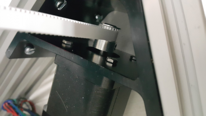
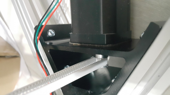
Next I attached the motors I'm using 48mm 0.9deg 1.68A nema 17 steppers (OMC stepperOnline), I could go to 2A with duet wifi and TMC 2600 drivers but did not think I would be running them that hard. There does seem to be a lot of comments about how difficult it is to fit the motors with cap headed screws as its difficult to get an allen key into the corners to tighten them so I used m3 plain hex bolts and a spanner.
I have used cork dampers between the motor and corners, I suspect using the TMC2600's interpolating 1/256th microstepping they will not resonate much but I had some so they got used.
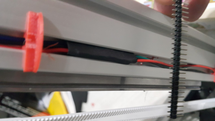
The endstop wiring is in place, I am using 2.54mm header pins with the pins pushed into the plastic so they are equal length both sides, to join pre-crimped wires (with some heatshrink tubing to keep them attached), these ready made cables sold as i3 wiring kits are very cheap from aliexpress and it cuts down on the soldering.
Now I am waiting on a Duet Wifi and paneldue, an E3D titan, and v6 hotend. I intend to have a laser/waterjet cut aluminium base plate to make the bottom of the electronics compartment, which will act as a heatsink with one push, one pull-fan on either side, where I hope to fit the 24v laptop style PSU, Duet wifi, an SSR25DA for the mains heated bed, some 24v to 12v converters to run the fans and hot end heater (I prefer to use 12v for most parts as I've plenty of spares lying around). I need to get the tooling plate cut to make the bed. I am going to use a 500w 220 vac silicone heater for the bed. Then its in to the hard part, getting it to print well. Really enjoying it so far.
Edited 1 time(s). Last edit at 08/22/2016 06:30PM by DjDemonD.
Simon Khoury
Co-founder of [www.precisionpiezo.co.uk] Accurate, repeatable, versatile Z-Probes
Published:Inventions
|
Re: Large Kossel all metal delta build log August 23, 2016 09:20AM |
Registered: 9 years ago Posts: 54 |
|
Re: Large Kossel all metal delta build log August 23, 2016 09:22AM |
Registered: 8 years ago Posts: 3,525 |
Thanks. Good point they might be a bit too flexible in 6mm. I'll see how it performs once the rest of the parts are delivered. I suppose I can always make new rods, possibly salvaging the balls from the current setup if there's any lack of rigidity in the arms. I am right in thinking the magnets are in the carriages/effector and the balls are just large ball bearings?
Simon Khoury
Co-founder of [www.precisionpiezo.co.uk] Accurate, repeatable, versatile Z-Probes
Published:Inventions
Simon Khoury
Co-founder of [www.precisionpiezo.co.uk] Accurate, repeatable, versatile Z-Probes
Published:Inventions
|
Re: Large Kossel all metal delta build log August 23, 2016 01:11PM |
Registered: 10 years ago Posts: 14,672 |
That looks a very nice build! If I ever re-do the mechanics of my delta, I plan to try 2040 extrusions and linear rails like your build.
I see that some people think steel-reinforced belts are not good in this application, because the steel fatigues too much going round the small pulleys.
I don't really see why you are using a 12V converter for the hot ends though, given that 24V heater cartridges don't cost much - I paid £8.43 for a pack of three.
You could use the same technique that you already did to make the arms the same length, only use 6mm i.d. tube for most of the arm length instead of just a small section in the middle.
Large delta printer [miscsolutions.wordpress.com], E3D tool changer, Robotdigg SCARA printer, Crane Quad and Ormerod
Disclosure: I design Duet electronics and work on RepRapFirmware, [duet3d.com].
I see that some people think steel-reinforced belts are not good in this application, because the steel fatigues too much going round the small pulleys.
I don't really see why you are using a 12V converter for the hot ends though, given that 24V heater cartridges don't cost much - I paid £8.43 for a pack of three.
Quote
DjDemonD
Good point they might be a bit too flexible in 6mm. I'll see how it performs once the rest of the parts are delivered. I suppose I can always make new rods, possibly salvaging the balls from the current setup if there's any lack of rigidity in the arms.
You could use the same technique that you already did to make the arms the same length, only use 6mm i.d. tube for most of the arm length instead of just a small section in the middle.
Large delta printer [miscsolutions.wordpress.com], E3D tool changer, Robotdigg SCARA printer, Crane Quad and Ormerod
Disclosure: I design Duet electronics and work on RepRapFirmware, [duet3d.com].
|
Re: Large Kossel all metal delta build log August 23, 2016 02:06PM |
Registered: 8 years ago Posts: 3,525 |
Hi David thanks for the upvote on the build, really appreciated. I'm only using 12v where practical as I've got loads of 12v hotend heaters and fans and I don't want to have two sets of spares, I'd like to keep all my hotends and fans interchangeable. However if this machine surpasses my others and they end up redundant, maybe that will change.
I will look at the rods once it's working, they feel pretty stiff but if I've ironed out everything else and its still slightly vague I'll know why. So far nothing moves, wobbles or has any noticeable play. If I enlarge them I'll cut the ends off and bond them into some larger tube.
Regarding the steel reinforced belts I am using them on my corexy with 16t pulleys and no noticeable problems yet, I have read a specification that states 12t pulleys are the minimum for steel reinforced belts, so hopefully I've got some margin to work with.
One thing I was going to mention above and forgot was that there is no belt tension adjustment mechanism built into these corners or carriages, so I intend to fit some printed tensioners of the type that deflect the belt and are locked in place, so they will not behave elastically under sudden changes in direction like the spring tensioners that seem popular. If printed versions work sub-optimally I'll look into having some aluminium ones machined, or see if they can be bought from China, as almost everything else can be.
Edited 1 time(s). Last edit at 08/23/2016 02:34PM by DjDemonD.
Simon Khoury
Co-founder of [www.precisionpiezo.co.uk] Accurate, repeatable, versatile Z-Probes
Published:Inventions
|
Re: Large Kossel all metal delta build log August 24, 2016 07:27PM |
Registered: 8 years ago Posts: 59 |
Nice build! This is the kind of machine I would build if I built a new delta today.
Linear rails are awesome. I switched from using V-rollers to linear rails and my effector tilt dropped like a stone!
The reason I don't use magnetic arms is the thing you mention in the last paragraph about belt tensioning. I'm using RobotDigg's carriages, and they have great convenient belt tensioning, so it would feel like a downgrade to suddenly not have that anymore. :-/
|
Re: Large Kossel all metal delta build log August 24, 2016 09:18PM |
Registered: 10 years ago Posts: 293 |
I've written to the RobotDigg folks and asked if they could source a metal carriage and effector for the Hayden style magnetic setup. I'm not to keen on those cup magnets they borrowed from the K800 style. I prefer Hayden's where the magnet is a passive part and not in contact with the ball.
|
Re: Large Kossel all metal delta build log August 25, 2016 04:46AM |
Registered: 8 years ago Posts: 3,525 |
I take it you mean these?
[www.blueeaglelabs.com]
They do look nice, I don't yet know how well the k800 style magnets will work, I've greased the balls and sockets. The whole setup feels extremely rigid, but it doesn't take much force to disconnect the effector. This certainly might be a part that gets changed depending on how well it functions.
As for belt tensioning, I remember seeing a tensioner that sits over the belts with a screw to adjust the tension, I couldn't find it so I've designed one, just have to get around to printing it, testing it and then maybe having some machined in aluminium.
Its good to know effector tilt is low with the rails as I am keen to use the IR sensor on this build. I have FSR's on my mini kossel which work great and are not affected by effector tilt, but I'm dubious they will work with a 330mm bed made from 5mm tooling plate. Also the bed on my mini kossel is not secure enough as it has to float on the FSR's and very occasionally I get a slight shift if the nozzle hits a blob and the bed clamps are slightly mal-adjusted.
Simon Khoury
Co-founder of [www.precisionpiezo.co.uk] Accurate, repeatable, versatile Z-Probes
Published:Inventions
|
Re: Large Kossel all metal delta build log August 25, 2016 02:53PM |
Registered: 8 years ago Posts: 3,525 |
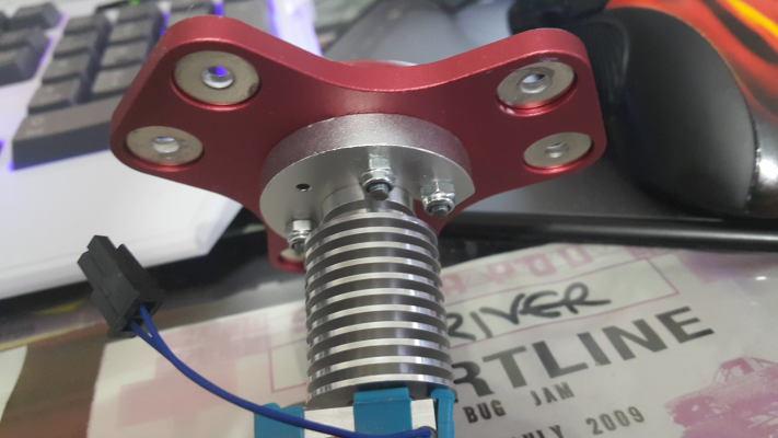
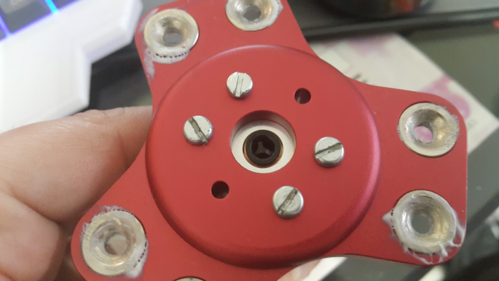
Can anyone explain how these groove mount adaptors for this metal effector are meant to be fitted. I've used 4 x m3 bolts and lock nuts but the hot end can still rotate in the mount and has a little play in it. There is a 5th hole in it, which is not threaded - I am sure this has something to do with tensioning the hot end against the adaptor once its fitted but I can't work out how.
Simon Khoury
Co-founder of [www.precisionpiezo.co.uk] Accurate, repeatable, versatile Z-Probes
Published:Inventions
Simon Khoury
Co-founder of [www.precisionpiezo.co.uk] Accurate, repeatable, versatile Z-Probes
Published:Inventions
|
Re: Large Kossel all metal delta build log August 25, 2016 05:41PM |
Registered: 10 years ago Posts: 14,672 |
Perhaps you need a shim in the recess in the effector, so that when you tighten up the groove mount it clamps the hot end against the end of the recess. A piece of paper might be sufficient.
I don't like the groove mount design, I prefer threaded holes in the top of the hot end.
Large delta printer [miscsolutions.wordpress.com], E3D tool changer, Robotdigg SCARA printer, Crane Quad and Ormerod
Disclosure: I design Duet electronics and work on RepRapFirmware, [duet3d.com].
I don't like the groove mount design, I prefer threaded holes in the top of the hot end.
Large delta printer [miscsolutions.wordpress.com], E3D tool changer, Robotdigg SCARA printer, Crane Quad and Ormerod
Disclosure: I design Duet electronics and work on RepRapFirmware, [duet3d.com].
|
Re: Large Kossel all metal delta build log August 25, 2016 05:59PM |
Registered: 8 years ago Posts: 3,525 |
I'll try that thanks.
Simon Khoury
Co-founder of [www.precisionpiezo.co.uk] Accurate, repeatable, versatile Z-Probes
Published:Inventions
Simon Khoury
Co-founder of [www.precisionpiezo.co.uk] Accurate, repeatable, versatile Z-Probes
Published:Inventions
|
Re: Large Kossel all metal delta build log August 26, 2016 04:57PM |
Registered: 8 years ago Posts: 3,525 |
So a double thickness of paper did the trick.
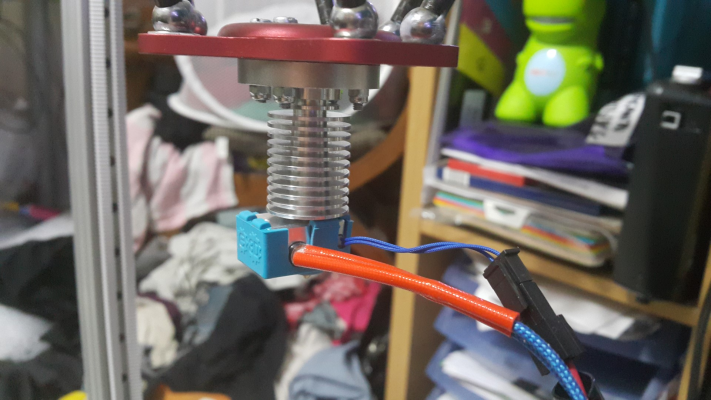
Hot end installed.
Cartridge thermistor a definite improvement, and E3D silicone cover a nice touch.
Tooling plate dropped off at local engineering firm to be made circular, hopefully with some nice bevelled and smoothed edges.
Local laser cutting company are going to make a bottom plate and a top cover for the electronics compartment.
Quite a struggle getting the STL's I'd designed into .dxg's for the laser cutter. In the words of Neville from Laserline, Bristol
"I fear we are both fluent, just in different languages."
Simon Khoury
Co-founder of [www.precisionpiezo.co.uk] Accurate, repeatable, versatile Z-Probes
Published:Inventions
|
Re: Large Kossel all metal delta build log August 29, 2016 05:16AM |
Registered: 8 years ago Posts: 601 |
|
Re: Large Kossel all metal delta build log August 29, 2016 05:17AM |
Registered: 8 years ago Posts: 3,525 |
From e3d
Sorry for the short reply I was driving.
Glad you're enjoying the log I was a bit concerned it would be boring.
E3d are supplying these with new v6 hot ends at the moment.
Edited 1 time(s). Last edit at 08/29/2016 06:19AM by DjDemonD.
Simon Khoury
Co-founder of [www.precisionpiezo.co.uk] Accurate, repeatable, versatile Z-Probes
Published:Inventions
|
Re: Large Kossel all metal delta build log August 31, 2016 04:23PM |
Registered: 8 years ago Posts: 3,525 |
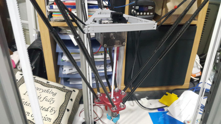
So decided that a flying extruder is the way forward having had so many great experiences with them before. Decided to make a new design to suit this machine. Although I probably should have gone for the extruder below the flying bracket, for an even shorter bowden tube, might reprint it later.
(please click on the image for portrait view).
E3D titan and 20mm nema 17 motor.
Simon Khoury
Co-founder of [www.precisionpiezo.co.uk] Accurate, repeatable, versatile Z-Probes
Published:Inventions
(please click on the image for portrait view).
E3D titan and 20mm nema 17 motor.
Simon Khoury
Co-founder of [www.precisionpiezo.co.uk] Accurate, repeatable, versatile Z-Probes
Published:Inventions
|
Re: Large Kossel all metal delta build log September 01, 2016 05:14PM |
Registered: 8 years ago Posts: 3,525 |
Yes definitely better with the extruder hanging down beneath.
Simon Khoury
Co-founder of [www.precisionpiezo.co.uk] Accurate, repeatable, versatile Z-Probes
Published:Inventions
Simon Khoury
Co-founder of [www.precisionpiezo.co.uk] Accurate, repeatable, versatile Z-Probes
Published:Inventions
|
Re: Large Kossel all metal delta build log September 02, 2016 04:24AM |
Registered: 11 years ago Posts: 973 |
hi
i have the same carriages the bracket on the carriage is it 3d printed as i need something like that on mine
Check my rubbish blog for my prusa i3
up and running
[3dimetech.blogspot.co.uk]
i have the same carriages the bracket on the carriage is it 3d printed as i need something like that on mine
Check my rubbish blog for my prusa i3
up and running
[3dimetech.blogspot.co.uk]
|
Re: Large Kossel all metal delta build log September 02, 2016 06:25AM |
Registered: 8 years ago Posts: 3,525 |
Here it is.
flyingextrudermountfork800carriages.stl
I did print some in petg they looked awful but they were a lot stronger than these ABS ones. If you use fairly light elastic they should be okay, I've got similar ones on my kossel mini and they've lasted 6 months, but the flying extruder is lighter.
Simon Khoury
Co-founder of [www.precisionpiezo.co.uk] Accurate, repeatable, versatile Z-Probes
Published:Inventions
|
Re: Large Kossel all metal delta build log September 03, 2016 06:18PM |
Registered: 8 years ago Posts: 3,525 |
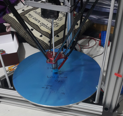
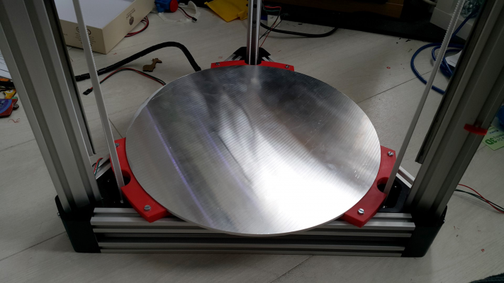
Very exciting the tooling plate is back from the CNC shop, cut to 330mm and nicely bevelled at the edges.
Decided for now to drop it into mounts which I've designed on a model of the printer, allowing space for some insulation and the silicone heater beneath. It should be well enough supported not to move or tilt in use, and can be easily lifted off to get at the electronics underneath. I am assuming it will be level as the mounts are all the same size and it should sit equidistant from the lower frame at each of the three places it is supported. I am assuming autocalibration can cope with a slight angle on the bed so long as it is flat (which it is).
Had to revise my model as the corners I downloaded to use as dummies were not the right type.
Simon Khoury
Co-founder of [www.precisionpiezo.co.uk] Accurate, repeatable, versatile Z-Probes
Published:Inventions
|
Re: Large Kossel all metal delta build log September 03, 2016 06:25PM |
Registered: 10 years ago Posts: 14,672 |
Delta auto calibration will not (yet) compensate perfectly for a bed that is tilted relative to the towers. However, if you are using metal frame corners, then you should be able to get your lower horizontal extrusions perpendicular to the towers. Then all you need to do is to get the bed parallel to the lower horizontals, which is easy.
Large delta printer [miscsolutions.wordpress.com], E3D tool changer, Robotdigg SCARA printer, Crane Quad and Ormerod
Disclosure: I design Duet electronics and work on RepRapFirmware, [duet3d.com].
Large delta printer [miscsolutions.wordpress.com], E3D tool changer, Robotdigg SCARA printer, Crane Quad and Ormerod
Disclosure: I design Duet electronics and work on RepRapFirmware, [duet3d.com].
|
Re: Large Kossel all metal delta build log September 04, 2016 05:04AM |
Registered: 8 years ago Posts: 3,525 |
It should sit fairly level but I can always place shims/washers under the brackets.
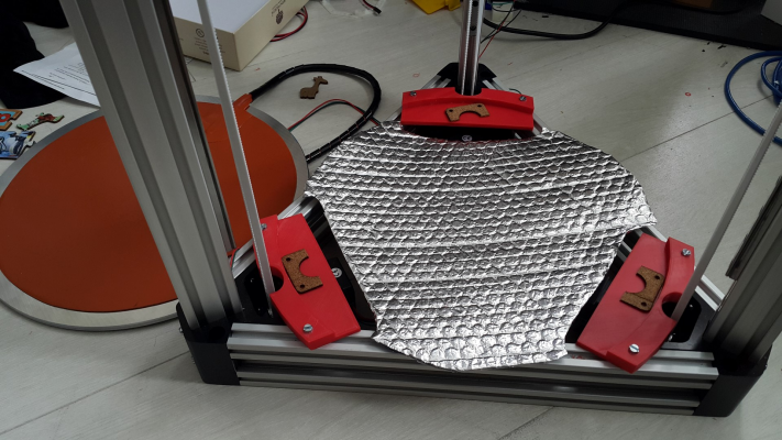
Here is the bed sat in place, the brackets needed to have their holes drilled out to 6mm to take m4 bolts and t-nuts (will make them 6mm if I upload the files) to allow enough wiggle room to get the bed to sit in place tightly but be able to be lifted out.
The heater is attached its 240v mains at 500w so should be up to the job.
In reality its not as "off centre" to the tooling plate as it looks in the image, the perspective is a bit off.
Its also a shame that the cabling is side mounted to these silicone heaters as I will have to have the wiring leaving the bed and re-entering the side of the electronics compartment.
I've made a sheet of insulation to go between the bed and the electronics underneath. This might be upgraded to a wooden/metal plate depending on how much heat spreads to the electronics. There will be two fans (push-pull) on the compartment under the bed.
I've used for now some spare bits of cork to sit the bed on, these will become a full cork layer on the bracket for better stability later. I am concerned that at 120 deg C the abs brackets will soften. They wont go very far as the brackets sit squarely on the frame. I might have to look to have these brackets milled in aluminium once I'm satisfied that they work.
Edited 2 time(s). Last edit at 09/04/2016 05:07AM by DjDemonD.
Simon Khoury
Co-founder of [www.precisionpiezo.co.uk] Accurate, repeatable, versatile Z-Probes
Published:Inventions
|
Re: Large Kossel all metal delta build log September 06, 2016 07:00AM |
Registered: 8 years ago Posts: 3,525 |
Does anyone know a source of cheap adjustable m6 feet? The best deal I can find is about £8-£10 for 3 on ebay. This seems like a lot for an m6 bolt with a rubber block on the end?
I am planning to tap the towers extrusions to attach the feet.
Maybe I ought to make some.
Simon Khoury
Co-founder of [www.precisionpiezo.co.uk] Accurate, repeatable, versatile Z-Probes
Published:Inventions
I am planning to tap the towers extrusions to attach the feet.
Maybe I ought to make some.
Simon Khoury
Co-founder of [www.precisionpiezo.co.uk] Accurate, repeatable, versatile Z-Probes
Published:Inventions
|
Re: Large Kossel all metal delta build log September 06, 2016 07:03AM |
Registered: 8 years ago Posts: 3,525 |
I found some on Amazon [www.amazon.co.uk]
But to get a good price I have had to buy 20. So if anyone wants some let me know.
Simon Khoury
Co-founder of [www.precisionpiezo.co.uk] Accurate, repeatable, versatile Z-Probes
Published:Inventions
But to get a good price I have had to buy 20. So if anyone wants some let me know.
Simon Khoury
Co-founder of [www.precisionpiezo.co.uk] Accurate, repeatable, versatile Z-Probes
Published:Inventions
|
Re: Large Kossel all metal delta build log September 06, 2016 07:41AM |
Registered: 10 years ago Posts: 14,672 |
Quote
DjDemonD
Does anyone know a source of cheap adjustable m6 feet? The best deal I can find is about £8-£10 for 3 on ebay. This seems like a lot for an m6 bolt with a rubber block on the end?
I am planning to tap the towers extrusions to attach the feet.
Maybe I ought to make some.
Why do you need adjustable ones? I printed 3 non-adjustable ones for my Kossel. Like you I tapped the tower extrusions to fit them.
Large delta printer [miscsolutions.wordpress.com], E3D tool changer, Robotdigg SCARA printer, Crane Quad and Ormerod
Disclosure: I design Duet electronics and work on RepRapFirmware, [duet3d.com].
|
Re: Large Kossel all metal delta build log September 06, 2016 07:49AM |
Registered: 8 years ago Posts: 3,525 |
I would not always be 100% confident that the surface the machine will sit on will be totally level. I intend to place some stick on circular spirit levels on the frame and on the effector to check for effector tilt. I also want to use rubber to insulate from any vibration and noise.
Simon Khoury
Co-founder of [www.precisionpiezo.co.uk] Accurate, repeatable, versatile Z-Probes
Published:Inventions
Simon Khoury
Co-founder of [www.precisionpiezo.co.uk] Accurate, repeatable, versatile Z-Probes
Published:Inventions
|
Re: Large Kossel all metal delta build log September 09, 2016 04:20PM |
Registered: 8 years ago Posts: 3,525 |
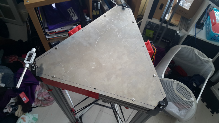
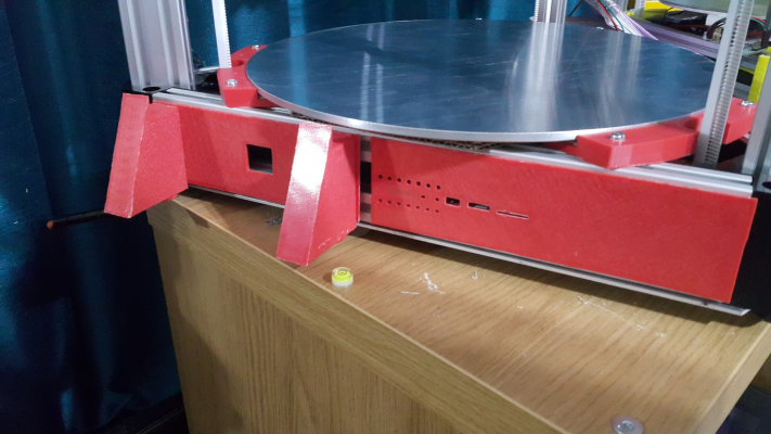
Got the aluminium panels back from the lasercutters. Attached with m4 bolts and tnuts, holes were 6mm to allow for any discrepancy between the model and the actual panel (there was a little bit). Should help to stiffen the lower part of the frame.
I have tapped the base of the tower extrusions for m6, and attached feet. (I have 17 spare if anyone wants some PM me).
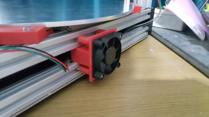
Going to try these fan cowls for the electronics compartment, as the designer pointed out without them most of the air just get channelled away down the extrusions outside the compartment. There is another one on the other side as an exhaust fan.
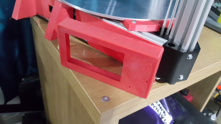
I have started making side panels (will upload to thingiverse when done) using push fit clips to hold them to the 2020's but I might drill some holes for t-nuts for the paneldue box and the mains inlet, these need to be stronger. The duetwifi panel is DC42's design which I have remixed with push fit clips. The Paneldue enclosure is this one and I've designed a bracket to stand it off and tilt it as I prefer my LCD below the bed at the front. Will upload it once I'm sure it works okay.
I've gone with Jinx's/my collaboration for an adjustable dual 30mm part fan with 30mm hotend fan for E3D v6. I will reprint it in red as the white doesn't look good on this machine.
Now desperately waiting on Duetwifi batch 3.
Edited 1 time(s). Last edit at 09/09/2016 04:25PM by DjDemonD.
Simon Khoury
Co-founder of [www.precisionpiezo.co.uk] Accurate, repeatable, versatile Z-Probes
Published:Inventions
|
Re: Large Kossel all metal delta build log September 09, 2016 04:33PM |
Registered: 8 years ago Posts: 601 |
|
Re: Large Kossel all metal delta build log September 09, 2016 04:58PM |
Registered: 8 years ago Posts: 3,525 |
Thanks.
£40 Inc the metal in 2mm alu, though I might do it myself if I do it again the laser cutting wasn't really necessary it's not too complex a shape. Don't know if it'll make the frame much stiffer, it's pretty stiff already but it won't make it more bendy
Simon Khoury
Co-founder of [www.precisionpiezo.co.uk] Accurate, repeatable, versatile Z-Probes
Published:Inventions
£40 Inc the metal in 2mm alu, though I might do it myself if I do it again the laser cutting wasn't really necessary it's not too complex a shape. Don't know if it'll make the frame much stiffer, it's pretty stiff already but it won't make it more bendy

Simon Khoury
Co-founder of [www.precisionpiezo.co.uk] Accurate, repeatable, versatile Z-Probes
Published:Inventions
|
Re: Large Kossel all metal delta build log September 10, 2016 12:20PM |
Registered: 8 years ago Posts: 3,525 |
So started on the 240v wiring.
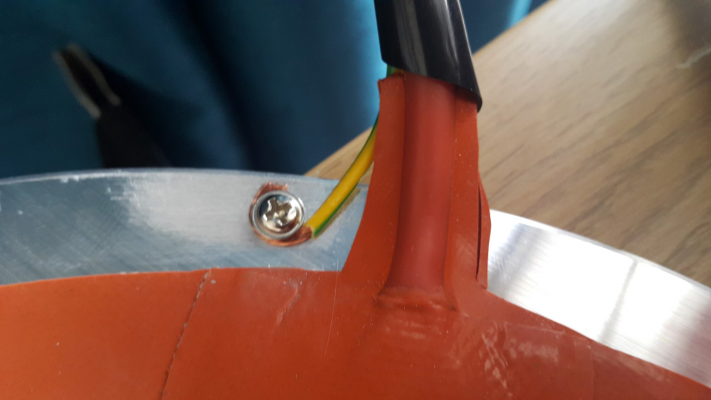
Drilled a hole and tapped the edge of the tooling plate, and attached an earth wire.
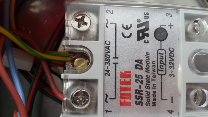
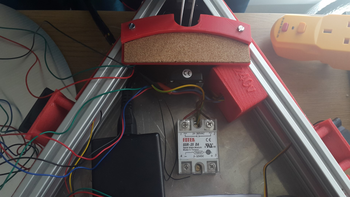
SSR25 DA attached to aluminium base plate (which should act as pretty good heatsink should it need it - probably not with a 500w heater), tapped m4 holes to fix it in place. I'm loving having so much metal to drill and tap, its a nice change.
Wired the heatbed 240v live through the AC side of the SSR. The retaining screw for the SSR seems like a pretty good place to join the bed earth wire, and to make the earth connection to the frame. One earth wire in the image is from the bed, the other goes to the 240v socket.
Wires attached to terminal block, one of the lives, is to the supply of the 24v PSU, one to the SSR. Neutrals to PSU & bed, Earth from PSU and frame+bed via the SSR backing plate.
Placed through the cover for a junction box (will be uploaded later) which fixed with tnuts to the frame.
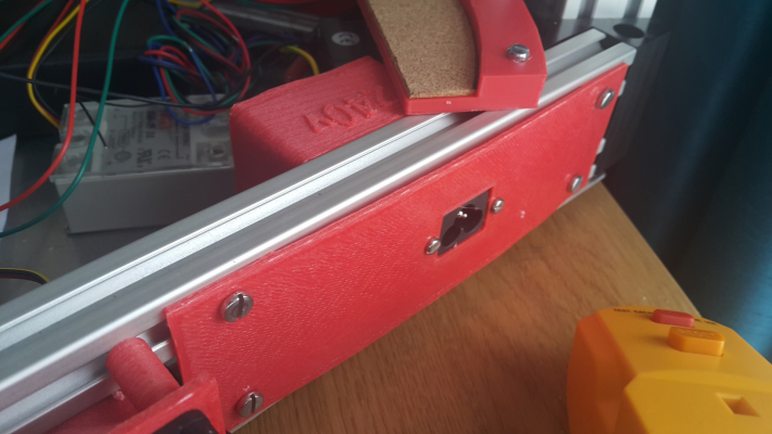
I have used a c6 "cloverleaf" socket as thats what my 24v PSU came with, plus its small compared to an IEC "kettle" type socket.
The socket is fixed to the side panel.
I did not take a photo inside the junction box before bonding the lid on with some superglue, but its just 3 soldered on mains wires connected straight through to the terminal block.
No switch as I intend to connect it to a switched socket next to the printer via a plug in RCD.
No fuse here either as the plug is fused, so I'm not sure what purpose placing another fuse here serves?
The completed bed and PSU mains wiring in place. I need to make a strong cable restraint for the cable bundle to the bed. The bed is intended to come off and be placed next to the machine if I need to get into the electronics compartment, but should it fall off the table, it is quite heavy, I'd like to hope I wont pull these wires out from their connections. I don't mind if I break the side panel if it falls off, that's probably preferable and would slow it down as it fell.
Final check - multimeter on continuity check, one lead on the cloverleaf earth pin, the other to the bed, and any/all metal parts of the frame. All good continuity, but interestingly the layer of aluminium oxide on the extrusions does not conduct that much, and you have to scratch through it with the multimeter probe to read the continuity. I suspect in the event of a short to live mains this will make little or no difference as the RCD will trip.
Now I need the duetwifi...... I was batch 3 so I would have expected to have it by now... patience needed.
Simon Khoury
Co-founder of [www.precisionpiezo.co.uk] Accurate, repeatable, versatile Z-Probes
Published:Inventions
Sorry, only registered users may post in this forum.
