My home Kossel build
Posted by av8r1
|
My home Kossel build October 02, 2016 08:12PM |
Registered: 7 years ago Posts: 129 |
I am a doofus.
I built a Folger Kossel kit for my maker space, and we've been struggling to get it calibrated. So naturally I started building one for home (see Line 1). I didn't buy FT's kit, but I started self-sourcing the parts figuring that
A: I had a lot of the parts like a power supply and RAMPS board lying around
B: I have a working Prusa and could 3D print many of the parts
C: I could eliminate a large amount of laser cut acrylic from the design
D: I could improve the design significantly (see Line 1).
E: I could do it cheaper than buying the kit (see Line 1).
The improvements I want to make include a glass heat bed, an E3D hot end (why on earth buy whatever Folger uses when a Lite6 is the same price?), DC42's IR bed probe rather than an inductive one, a better spool holder, etc.
As of this writing, I have the frame assembled with the motors in place, sliders and carriages installed, and that's about it. Before I go any further in construction, I want to verify that I have nothing else to do geometry wise. The towers are equidistant and perpendicular to the base and top triangle frames.
I sourced my 2020 beams, hardware and motors from Folger. I'm going to get my hot end and sensor from Filastruder. I need some end stops, which I can get virtually anywhere, but I just realized something. My printer is 300x700mm. Most end stop boards (and I like the modular boards) come with 700mm cables (see Line 1). I could make some, but don't have a crimper for either kind of end, nor can I find an efficient supplier for all the bits. Does anyone have a cheap solution where I don't end up paying $40 for end stops? I also need a PCB heat bed, which I'll get from Fleabay.
I also need diagonal rods. The problem I'm running into here is that everyone else is a doofus. No one. In the world. Publishes complete specs. For their rod ends. My effector and carriages take M3 screws. I can't find any data on any rod ends anywhere for the ID of the balls. The sheer lack of effort manufacturers put into things like listing specs for their products is why I want to grow all of my own food. So, I'm going to wait a while and gather some info before pulling the trigger on any graphite.
I just now ordered my hot end and sensor. I'll assemble the hot end while gathering info on push rods.
I printed all the parts in PET. I love that plastic. The frame is much more rigid with aluminum rather than plastic corners, but I'm trying to be cheap (see Line 1).
Pics to follow of the build so far.
|
Re: My home Kossel build October 03, 2016 03:33AM |
Registered: 9 years ago Posts: 1,159 |
|
Re: My home Kossel build October 03, 2016 06:13AM |
Registered: 8 years ago Posts: 5,232 |
I got my 6x4 carbon rods in length of 300 and 330mm from a kite manufacturer ( shorter rods were also available) . They sold them in sets of 2 rods and I found them pretty precisely cut. They had all the same length.
I'd go for a 250mm silicon bed heater from robotdigg instead of the PCB type. They are available in 24V too, which is my favorite voltage for a delta.
I'd go for a 250mm silicon bed heater from robotdigg instead of the PCB type. They are available in 24V too, which is my favorite voltage for a delta.
|
Re: My home Kossel build October 03, 2016 10:24AM |
Registered: 10 years ago Posts: 14,672 |
Quote
av8r1
I also need diagonal rods. The problem I'm running into here is that everyone else is a doofus. No one. In the world. Publishes complete specs. For their rod ends. My effector and carriages take M3 screws. I can't find any data on any rod ends anywhere for the ID of the balls. The sheer lack of effort manufacturers put into things like listing specs for their products is why I want to grow all of my own food. So, I'm going to wait a while and gather some info before pulling the trigger on any graphite.
I list the parts needed (joints, CF tube and set screws) for making rods in my blog at [miscsolutions.wordpress.com]. The Traxxas joints I list are compatible with M3 screws.
Large delta printer [miscsolutions.wordpress.com], E3D tool changer, Robotdigg SCARA printer, Crane Quad and Ormerod
Disclosure: I design Duet electronics and work on RepRapFirmware, [duet3d.com].
|
Re: My home Kossel build October 04, 2016 04:05AM |
Registered: 7 years ago Posts: 129 |
I appreciate the responses, folks!
First, let's talk about heat beds. O lampe, I'm going to go with 12 volts on this printer, because I happened to have a 12 volt power supply lying around. Other than speed of heating, is there any reason to go with silicone over PCB heating? On that note, what is the temperature limit of a PCB heater? I haven't found any documentation on that (I'm noticing a pattern here. I guess specifications are for engineers and other losers, huh?), so I limit my Prusa's PCB bed to 100C. I don't tend to print higher than that anyway.
As for a 250mm diameter build area. It might be nice to extend it that big, but I just cracked open QCAD to figure this out. A 250mm diameter disc just barely doesn't fit inside my frame. It overhangs the outer edges of the 2020 by about a millimeter at each side. That's kind of cool since I could hold down a plate with a simple vertical standoff and a T-nut. I'm not imagining I could use all of that volume, though, probably 220mm of it at max due to the angles of the diagonal rods.
Speaking of diagonal rods. Folger uses a 200mm build plate, and they call for 240mm diagonal rods. We cut ours to 230 due to a math snafu. Trying to calibrate the printer, it seems the maximum radius the nozzle can reasonably reach like that is 80mm from bed center, and we seem to get some effector tilt out that far. I'm wondering if there's any profit in cutting the rods to 250mm instead. Note I am not using the same effector as included in the Folger kit, because that design is hideous. I found one on Thingiverse with an offset of 20mm.
I'm not terribly worried about large print volume, as I haven't maxed out my Prusa yet. Mostly I'm after additional speed and because I have nothing else to do with my life.
|
Re: My home Kossel build October 04, 2016 08:44AM |
Registered: 8 years ago Posts: 3,525 |
I've got two deltas with "oversized" beds, to the point where I see deltas where the bed is entirely within the lower horizontals and think they look odd.
I happily take PCB heaters up to 120 deg C, if you have a good power supply and nice thick cables, and your ramps board can handle the current. If in doubt consider an electro-mechanical relay (cheap and easy) and using bang-bang for heated beds. Getting the bed high current switching off the ramps board eliminates the biggest cause of fire/failure.
Longer rods don't cause a problem except less build height, but shorter rods can cause issues. Reaching the extremities of your print bed seems like something you want to do slightly more often than building objects really tall, or maybe that's just me. It seems a common statement amongst delta printer owners "I wish I'd made my rods another 30mm longer". I wish mine were 30mm longer too!
Simon Khoury
Co-founder of [www.precisionpiezo.co.uk] Accurate, repeatable, versatile Z-Probes
Published:Inventions
|
Re: My home Kossel build October 04, 2016 04:07PM |
Registered: 7 years ago Posts: 129 |
|
Re: My home Kossel build October 04, 2016 04:11PM |
Registered: 8 years ago Posts: 3,525 |
Depends on what you're printing and what you're printing on. I use printbite, it's really good, but you need the bed thermistor to be reading 120 to get the first layer stuck.
Simon Khoury
Co-founder of [www.precisionpiezo.co.uk] Accurate, repeatable, versatile Z-Probes
Published:Inventions
Simon Khoury
Co-founder of [www.precisionpiezo.co.uk] Accurate, repeatable, versatile Z-Probes
Published:Inventions
|
Re: My home Kossel build October 04, 2016 06:39PM |
Registered: 7 years ago Posts: 129 |
|
Re: My home Kossel build October 04, 2016 06:44PM |
Registered: 7 years ago Posts: 59 |
If you haven't built the rods yet I have a guide in this post about how to do rods with traxxas ends.
[www.thingiverse.com]
Rod guide with pics is half way down in the instructions on the printer build. Not sure if the sleeves I use will work for your printer, just use the extrusion jig and rotation alignment techniques to ensure accurate lengths.
Edited 1 time(s). Last edit at 10/04/2016 06:47PM by Milton.
|
Re: My home Kossel build February 02, 2017 12:17AM |
Registered: 7 years ago Posts: 129 |
Update on this nearly forgotten project:
So I've got the thing "working." It squirts filament into shapes vaguely resembling the STLs I feed it.
I'm rather disappointed in the performance. First of all, bed leveling does not work. They've put code in RC8 of Marlin that reads as if they have it working, but they don't. It does not adjust for the angle of the bed, now it just adjusts for height. I don't know why I keep trying it. Oh right, see Line 1.
The other thing is the hot end. I'm using an E3Dv6 hot end with bowden tube, and a Mk.9 drive wheel setup from Folgertech. It can barely push the filament. I don't think I've got it built wrong, but it takes a huge amount of force to extrude filament. It doesn't take much to push filament through the hot end without any teflon in it, it doesn't take much to push it through the bowden tube, but through the whole assembly...
I don't know. I shouldn't have built it. I should have bought snacks instead.
|
Re: My home Kossel build February 02, 2017 03:11PM |
Registered: 8 years ago Posts: 3,525 |
Snacks are good and much less frustration than delta 3d printers.
I don't know why the extruder is performing badly, check everything is smooth, cut your teflon tubing at exactly 90 degrees, gently and with a very sharp knife, so you don't squash it or create burs. If you can push filament through a heated hot end then it isnt that. Are you giving the motor enough power? Idler wheel too tight?
For deltas marlin is not that fully featured. RC8 does basic delta calibration but its only really endstops, and you can enter rod length and delta radius. Oddly it will do per-rod length corrections but not bed tilt properly (endstop corrections can partially correct for tilt) and not tower position adjustments. Auto levelling is only useful if you have a good calibration but perhaps a tilted bed. Grid or bilinear auto levelling is more useful but usually for uneven beds rather than just tilted. If your bed is flat and of modest size (upto 200mm) then a correctly calibrated delta should allow the nozzle to track at a constant height to almost the edges.
Delta calibration is more complex, you have to get your endstops adjusted correctly then adjust radius to remove concave or convex nozzle movement as you go from one side of the bed to another, then adjust rod length to get correctly scaled objects and recheck everything else again. Consider installing Rich Cattel's version running autocalibration, writing down all the parameters presuming it finds a solution reasonably convincingly and then using these values to configure regular Marlin (or repetier firmware). Or join the revolution and get a duet and just hit autocalibrate and 20 seconds later you're done.
Simon Khoury
Co-founder of [www.precisionpiezo.co.uk] Accurate, repeatable, versatile Z-Probes
Published:Inventions
|
Re: My home Kossel build February 06, 2017 11:20AM |
Registered: 8 years ago Posts: 9 |
Hi AV8R1
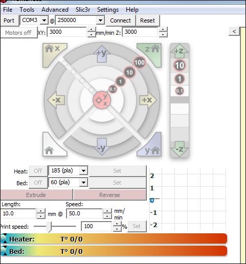
I also have a Folger Kossel and the extruder drive does work. Check the speed setting that you have set in Pronterface. The speed and extrusion length can be seen at the bottom of the attached file.
DjDeamonD is correct about the bed leveling. Mine didn't work either so eventually I gave up and did it manually with a feeler gauge. I installed endstop adjustment screws on the top of my carriages and instead of adjusting the bed adjusted the plane of the endstops positions. Seems to work. Then you just have to enter a Z height adjustment into your slicer. When I print I have to set the scale to 97% to get correct sizing. I don't know how to fix this.
I've also recently modified my extruder to a flying extruder arrangement. Not difficult to do.
|
Re: My home Kossel build February 06, 2017 11:36AM |
Registered: 8 years ago Posts: 3,525 |
Hi Seraph1M, if you want to get scaling right you need to change your diagonal rod length in the firmware. Increase it if objects are too small, decrease it if they are too big. I used the same % change as the object size discrepancy but you might have to nudge it up and down a bit to be sure, bear in mind if you print in ABS it shrinks a bit on cooling around 0.7%. So increase diagonal rod length by 3%. But.... once you change it, other factors like the endstops or concave/convex correction (delta radius) will change, as they are all linked together mathematically. So you change your rod length then recalibrate around the new rod length, then print and check dimensions in X and Y, so its a bit tedious but very satisfying when you get 40mm cubes coming out 40.02mm in X and Y. Please also be aware Z is purely dependant on the steps/mm being correct and nothing to do with rod length.
So ideally use the escher3d manual calc, put in your values with your new rod length (change it in firmware), and then go around the suggested points, measuring the discrepancy of the nozzle above or below z=0, using the paper test. Enter them and then use the new values it suggests. Unless you are using really old firmware get rid of the screws on the carriages, use firmware endstop adjustments which the calc will generate for you automatically. If you create macros in your host program, to move to the locations you save yourself loads of time. One or two cycles usually does the trick. My microdelta went from dubious calibration to perfect, exactly 0 at each of 7 points after two cycles of this process. Also set your z-minimum travel limit to -2, then you can lower the nozzle down below z=0 if you need to, rather than use feeler gauges for any points where the nozzle is too high.
Edited 1 time(s). Last edit at 02/06/2017 11:38AM by DjDemonD.
Simon Khoury
Co-founder of [www.precisionpiezo.co.uk] Accurate, repeatable, versatile Z-Probes
Published:Inventions
|
Re: My home Kossel build February 11, 2017 03:54PM |
Registered: 7 years ago Posts: 129 |
I don't use Pronterface or Repetier Host, I save G-Code to SD card and use a discount smart controller.
I've got the extruder sorted out, it was a misalignment between the bore of the bowden tube and the hot end. The teflon tube wasn't uniformly thick, it's bore was off to one side, so it had some friction where teflon met steel in the heat break. It still has more friction than my direct drive Prusa, but it's gonna. I'm also running the nozzle slightly hotter.
I'm using a RAMPS stack with Marlin because that's what I had lying around. Should I get the mechanicals good and set, I'll go with a Duet Wifi I think, but right now this is what I've got.
I don't know if it's a repeatability issue with my transparent glass bed and red PCB heater, or if I'm just a dunce at setting it up, but I couldn't get the bed probe to function properly. So I said a lot of swear words, put the bed on springs, and level it by hand.
I've got the calibration pretty close, though it could still use work.
|
Re: My home Kossel build February 12, 2017 04:37AM |
Registered: 7 years ago Posts: 129 |
I just ran a 40mm calibration cube. X and Y are about 40.05mm. That's good enough, over the printable diameter of the bed, that's about a quarter millimeter error, and it might not even actually exist at all...
...Because my Z height is 39.84. Printing at 0.2mm layer height, I've lost almost a whole layer in 40 millimeters. I printed a 125mm tall object, it came out to 124.56. Allowing for a coefficient for first layer leveling error (i tend to run on the close side of just right), the error is pretty much dead on, 3 times the height, 3 times the error.
Current steps/mm is 80 exactly, doing the math, correcting the Z height would give me steps of 80.3/mm. If I were to change that, I would have to change both diagonal rod and delta radius settings, wouldn't I?
So debating on whether or not to bother. I got screwed once due to a Z height error; my Prusa was printing 1mm in 20 too short, so the 60mm tall lower corner blocks of my Delta came out 57.2mm tall--the bolt holes for my NEMA 17's didn't line up, and I had to reprint the corners. This is a fifth of the error, over the entire height of the printer, I'd lose 1.4mm. Think it's worth bothering over?
|
Re: My home Kossel build February 12, 2017 04:58AM |
Registered: 8 years ago Posts: 916 |
That error is consistent with what I've measured over many belts. Set the steps/mm to 80.3mm, and your first layer will probably be flatter (assuming you've actually measured your diagonal rods accurately).
For reference my steps per mm need to be 160.6 (calculated value is 160) to get perfectly sized parts. Halve this value due to my using 0.9 degree stepper vs your 1.8 degree steppers, and what value do you get?
For reference my steps per mm need to be 160.6 (calculated value is 160) to get perfectly sized parts. Halve this value due to my using 0.9 degree stepper vs your 1.8 degree steppers, and what value do you get?
|
Re: My home Kossel build February 12, 2017 06:01AM |
Registered: 8 years ago Posts: 3,525 |
Could not the 0.16mm just be first layer squash? I know you said you've compensated for levelling but I print 0.3mm first layers so 0.16 is just half a layer.
Try printing the object scaled in x2 in z see if it's still 0.16mm or whether it's 0.32?
Simon Khoury
Co-founder of [www.precisionpiezo.co.uk] Accurate, repeatable, versatile Z-Probes
Published:Inventions
Try printing the object scaled in x2 in z see if it's still 0.16mm or whether it's 0.32?
Simon Khoury
Co-founder of [www.precisionpiezo.co.uk] Accurate, repeatable, versatile Z-Probes
Published:Inventions
|
Re: My home Kossel build February 12, 2017 06:33AM |
Registered: 8 years ago Posts: 916 |
Quote
DjDemonD
Could not the 0.16mm just be first layer squash? I know you said you've compensated for levelling but I print 0.3mm first layers so 0.16 is just half a layer.
Try printing the object scaled in x2 in z see if it's still 0.16mm or whether it's 0.32?
He's already tried that, 3 times the height, 3 times the error.
|
Re: My home Kossel build February 12, 2017 07:34AM |
Registered: 7 years ago Posts: 129 |
80.3 steps/mm is a familiar number, that's what I've got my Prusa's X and Y axes set to, and the motors, pulleys and belts are from the same vendor.
I print a 0.2mm first layer, so I doubt I've lost 1.6mm to that alone. I could correct the overall height of a calibration cube by leveling the bed slightly lower and increasing the multiplier of the first layer, but that wouldn't do anything for actual features of a print, such as the bolt pattern I posted about previously. I print a lot of functional items (I'm really happy with a tablet stand I designed, and that 125mm tall object is a part for a desk) so I need the thing to run true if it's going to be any use to me.
So I should be good dimensionally in X and Y if I slightly change the steps/mm...Ah what the heck, I can change it back if it messes things up.
|
Re: My home Kossel build February 12, 2017 01:07PM |
Registered: 8 years ago Posts: 3,525 |
Quote
nebbian
Quote
DjDemonD
Could not the 0.16mm just be first layer squash? I know you said you've compensated for levelling but I print 0.3mm first layers so 0.16 is just half a layer.
Try printing the object scaled in x2 in z see if it's still 0.16mm or whether it's 0.32?
He's already tried that, 3 times the height, 3 times the error.
Yeah sorry just noticed that.
Simon Khoury
Co-founder of [www.precisionpiezo.co.uk] Accurate, repeatable, versatile Z-Probes
Published:Inventions
|
Re: My home Kossel build February 16, 2017 01:25AM |
Registered: 7 years ago Posts: 129 |
|
Re: My home Kossel build February 16, 2017 02:15AM |
Registered: 8 years ago Posts: 916 |
|
Re: My home Kossel build February 16, 2017 10:54AM |
Registered: 7 years ago Posts: 129 |
I did end up changing the Z homed height (or whatever Marlin calls that dimension) because more steps/mm means it's travelling farther. I believe I rounded down to the nearest millimeter and leveled the bed manually. What I'm tempted to do is make a part with two points in the sides and measure between the points, rather than the whole thickness. That way, I'll eliminate the first layer as a variable.
Edited 1 time(s). Last edit at 02/16/2017 10:55AM by av8r1.
Edited 1 time(s). Last edit at 02/16/2017 10:55AM by av8r1.
|
Re: My home Kossel build February 18, 2017 09:53AM |
Registered: 7 years ago Posts: 129 |
So, I'm still trying to wrap my head around the interconnectedness of the various attributes of a Delta.
From what I understand, the three variables necessary to calibrate the printer are:
Axis steps/mm. This directly controls Z-height and has an effect on XY dimensional accuracy
Delta Radius. This variable is calculated by subtracting three "offset" variables, so increasing any one of those by X will increase Delta Radius by X. This variable controls "flatness," or the position of the effector at the edge of the bed compared to the center.
Diagonal Rod Length. This variable controls X/Y dimensional accuracy.
If I change any of these variables, I always have to recalibrate the other two?
|
Re: My home Kossel build February 18, 2017 10:50AM |
Registered: 8 years ago Posts: 3,525 |
Sounds like you have the broad brush strokes there. Don't forget endstop adjustments. You can either have endstops with screws to trigger them (oldschool) that you can adjust, or use M commands (more modern) to set the endstop corrections.
What you have in your post above, plus the endstop corrections will get you a long way probably all the way there if your printer is small or medium sized (upto 200mm bed), you'll work out some of the finer points during and after using these main factors, and you might need them if you have a larger printer. These include tower position corrections (if your towers are not all exactly at 60 degrees on a circle), tower radius corrections (towers not all on the same circle), per rod pair corrections (so compensation for sets of rods shorter than others - not used much), tower lean correction (not many firmwares can do this), there are more I've heard DC42 mention 20 factors that could be used to perfectly adapt a delta robot to move precisely within its build volume.
Reality is you will be likely to use autocalibration or manual calibration assisted by Escher3D calculator (which is really autocalibration but you have to enter the height differences by measuring with paper and jogging up and down at each point, instead of getting a probe to do the measuring).
Edit - axis steps/mm doesnt directly affect XY object size but might if everything else is poorly calibrated.
If you change any one of these factors, then yes you ought to re-calibrate but with the auto/manual calc to assist methods this is between a 40 second job and a 15 minute job, no more.
Edited 2 time(s). Last edit at 02/18/2017 11:05AM by DjDemonD.
Simon Khoury
Co-founder of [www.precisionpiezo.co.uk] Accurate, repeatable, versatile Z-Probes
Published:Inventions
|
Re: My home Kossel build February 19, 2017 06:09AM |
Registered: 7 years ago Posts: 129 |
My towers are equidistant to within a millimeter, measured between outer corners of the 2020 channel.
My diagonal rods are precisely the same length. They were cut and assembled on the same jigs.
Theoretically the arms could reach a 220mm radius, but I've got a 200mm sheet of glass and with the clips to hold it on the heater that makes for a 180mm radius build volume.
I have adjuster screws, both on the carriage and at the bed. I prefer mechanical solutions to software solutions.
I don't know if it's worth messing with. I have my Prusa for exact parts. I'll get this machine kitted up with a duet board at some point and use autocalibration.
|
Re: My home Kossel build February 19, 2017 06:16AM |
Registered: 8 years ago Posts: 3,525 |
Sounds good but I'd aim for 0.1mm precision on the frame, 1mm is going to be noticeable in your calibration which won't be that precise. Make sure you measure at the top of the towers and at the base. Sounds pedantic but that's deltas. Plus at this stage spending time tweaking the frame is time well spent and you might be less inclined to tweak it later.
Your choice on the mechanical adjustment rather than software but my two penny's worth - every millimeter of movement of your deltabot is entirely dependant on software to achieve it (except pure z moves) so using software to set endstops for example is just saving you time and increasing precision. It's good learning to start with adjustment screws, but move to software later. Getting the bed physically level with the towers is a great idea though.
Edited 3 time(s). Last edit at 02/19/2017 06:24AM by DjDemonD.
Simon Khoury
Co-founder of [www.precisionpiezo.co.uk] Accurate, repeatable, versatile Z-Probes
Published:Inventions
|
Re: My home Kossel build February 19, 2017 12:35PM |
Registered: 7 years ago Posts: 129 |
PM me and I'll give you my home address and you can come over and try that. I'm not going to.
The corner brackets of my frame are PETG, printed on a machine that was squared with a tape measure. Half of the screws holding the frame together are only accessible with the short end of an allen key. It's all held together with T-nuts. There is no diagonal bracing of any description. The frame isn't rigid enough to hold that kind of precision, even if I were willing to put in the kind of effort necessary to adjust parts of this nature in relation to each other by fractions of a millimeter.
To be clear, I am not willing to put in that kind of effort. At this stage, I'm willing to recompile the firmware one or two more times and if it doesn't get better, I'll put it back in the parts bin. I am already far beyond the point of diminishing returns. For the resources I've put into this delta, I could have built a knee-bucklingly good CoreXY.
The calbration cube I printed at the start of this whole insipid flustercluck was pretty damn good, all things considered. X and Y were within 0.05mm of nominal, and 0.01 of each other. When I design parts, I round to the nearest 0.1mm, so we're well within tolerance. The Z is out by approx. 0.2mm in 40mm. I make an adjustment that's supposed to directly effect Z height. I run the same G-Code, I gain .2mm in X and Y, and absolutely no change in Z. Both cubes read identical in Z height to the hundredth of a millimeter. It makes less sense than my dating history.
It's not appreciably faster than my Prusa. It cost more to build, it's harder to calibrate, it has a smaller build volume, it takes up more space, it's more awkward to move around...I will give it this, it's never slipped a layer.
Bottom line: If it comes down to loosening frame screws, I'm just gonna take it apart and build something else with the bits.
|
Re: My home Kossel build February 19, 2017 12:42PM |
Registered: 8 years ago Posts: 3,525 |
Fair enough I didn't realise you were at the end of your tether. In which case I apologise. Deltas are frustrating but they do work wonderfully when everything is right but this is difficult to do. I designed a micro delta with a totally novel frame, put it together and it worked. So it can be done. There's just no leeway for anything being out by very much at all.
Maybe you might get more out of the parts made into a corexy but they aren't without their headaches either.
Edited 1 time(s). Last edit at 02/19/2017 12:43PM by DjDemonD.
Simon Khoury
Co-founder of [www.precisionpiezo.co.uk] Accurate, repeatable, versatile Z-Probes
Published:Inventions
Maybe you might get more out of the parts made into a corexy but they aren't without their headaches either.
Edited 1 time(s). Last edit at 02/19/2017 12:43PM by DjDemonD.
Simon Khoury
Co-founder of [www.precisionpiezo.co.uk] Accurate, repeatable, versatile Z-Probes
Published:Inventions
Sorry, only registered users may post in this forum.