|
New Delta Project October 10, 2016 04:37PM |
Registered: 8 years ago Posts: 8 |
Hi All,
Looking for some words of advice.
I'm currently in the process of building a custom delta printer.
This is my second build, my first being a Rostock which is working well.
With the Rostock, I printed out the plans and cut out the wood, but on this one I'm making it all from scratch.
I'm following the information found here, and I would appreciate someone to take a look over my numbers to make sure my thinking is correct before I start cutting materials up.
I have used a few of the simulators and I am getting different results, so I guess i'm doing something wrong.
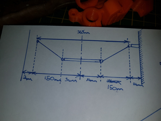
I want a printer with a 300mm build platform. Here's what I have:
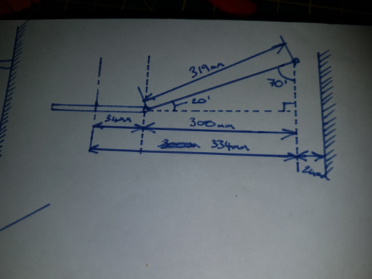
I did a few drawings to get to these numbers and i "think" they are correct, but I have a nagging feeling the arm length is incorrect.
Am I on the right track?
TIA Steve
Looking for some words of advice.
I'm currently in the process of building a custom delta printer.
This is my second build, my first being a Rostock which is working well.
With the Rostock, I printed out the plans and cut out the wood, but on this one I'm making it all from scratch.
I'm following the information found here, and I would appreciate someone to take a look over my numbers to make sure my thinking is correct before I start cutting materials up.
I have used a few of the simulators and I am getting different results, so I guess i'm doing something wrong.
I want a printer with a 300mm build platform. Here's what I have:
- Effector Offset - 34mm
- Carriage Offset - 24mm
- Print Area - 300mm Dia
- Rod Length - 319mm (calculated at full travel and a min angle of 20')
I did a few drawings to get to these numbers and i "think" they are correct, but I have a nagging feeling the arm length is incorrect.
Am I on the right track?
TIA Steve
|
Re: New Delta Project October 10, 2016 05:30PM |
Registered: 9 years ago Posts: 189 |
|
Re: New Delta Project October 10, 2016 06:19PM |
Registered: 9 years ago Posts: 483 |
|
Re: New Delta Project October 10, 2016 06:35PM |
Registered: 8 years ago Posts: 8 |
Thanks for the replies.
Tried a few of the online simulators and I'm getting different values for the arms, so either I'm doing something wrong or they are using different calculations. Plus this one doesn't have values for effector offset or carriage offset. I'm not even sure about the diameter of the " machine" is the print bed size vs overall machine diameter.
As for the napkin drawings, sadly it's how I personally process info. Plus an A4 sheet of paper is cheaper than a full blown cad package.
I guess I'm looking to validate the calculations are in the right ballpark.
Worst case scenario I'll have to make a few sets of arms at various lengths.
P.s I'd be interested what the min arm angle is at full stretch with the 350+ arms.
Mine is calculated at the minimum recommended by this site (20')
Edited 2 time(s). Last edit at 10/10/2016 06:39PM by Tumbledown.
|
Re: New Delta Project October 10, 2016 10:39PM |
Registered: 9 years ago Posts: 483 |
Fusion 360 is free, so the only real expense is the time it takes to learn it.
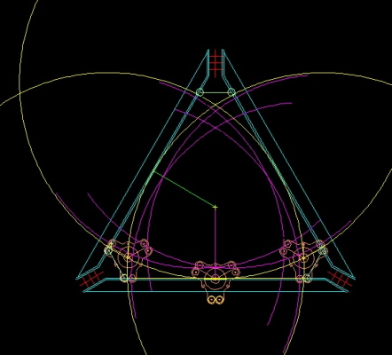
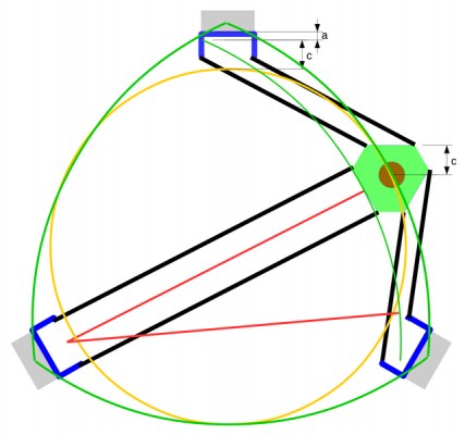
The length of the arms depends on whether or not you want the entire print bed inside the horizontals or not. Inside requires longer arms. The actual printable shape is not a circle, but a Reuleaux triangle. The calculators should specify what shape of the print area they are calculating in order to be useful.
Here's how I determined the print area in 2D Cad:
Purple arcs are the effector balls' maximum paths, yellow arcs are the maximum nozzle paths.
|
Re: New Delta Project October 11, 2016 04:58AM |
Registered: 8 years ago Posts: 8 |
So would a max reach of 300mm (effector joints/334mm nozzle) not give me a 300mm print circle as denoted on the Rostock schematic page?
|
Re: New Delta Project October 11, 2016 01:03PM |
Registered: 9 years ago Posts: 483 |
|
Re: New Delta Project October 11, 2016 01:13PM |
Registered: 8 years ago Posts: 8 |
|
Re: New Delta Project October 13, 2016 06:23PM |
Registered: 8 years ago Posts: 3,525 |
Not scientific but my larger delta's 330mm bed of which I set 300mm printable has 340mm arms but I'd add 20mm to them if I reworked them. The slight loss of build height would be worth it for less extreme arm to effector angles at the extremities. This is especially so for me with k800 style magnet arms, they're more prone to coming undone at these angles.
Simon Khoury
Co-founder of [www.precisionpiezo.co.uk] Accurate, repeatable, versatile Z-Probes
Published:Inventions
Simon Khoury
Co-founder of [www.precisionpiezo.co.uk] Accurate, repeatable, versatile Z-Probes
Published:Inventions
|
Re: New Delta Project October 15, 2016 05:39PM |
Registered: 11 years ago Posts: 805 |
Printing outside the towers. Has that actually been done successfully?
I thought about that when I planned my delta 2 year ago, but I had trouble finding joints that could move more then 60deg reliably. My traxxas joint where working well and my frame oversized so the area inside the towers was enough for that time. I also bought magnetic joints but the magnetic ends started to scratch away the surface of the ball ends, so I abandoned them for the traxxas.
Afaik even igus joints and all the stuff you find on ali also dont go beyond 60deg.
Also how would the precision be so far from the center?
|
Re: New Delta Project October 16, 2016 12:41AM |
Registered: 10 years ago Posts: 14,672 |
Printing outside the towers is certainly possible. As you said, it is all about having enough movement in the joints. Traxxas joints are very good in this respect, but Igus joints have less range of movement.
When using magnetic joints, the plastic cups must be designed to keep the magnets a short distance away from the balls so that they don't quite touch.
Large delta printer [miscsolutions.wordpress.com], E3D tool changer, Robotdigg SCARA printer, Crane Quad and Ormerod
Disclosure: I design Duet electronics and work on RepRapFirmware, [duet3d.com].
|
Re: New Delta Project October 16, 2016 04:54AM |
Registered: 9 years ago Posts: 483 |
Quote
sungod3k
Printing outside the towers. Has that actually been done successfully?
I assume you mean printing outside of the horizontals? Mine can theoretically go outside the horizontals, but I haven't had any reason to try actually printing there yet.
Quote
sungod3k
I also bought magnetic joints but the magnetic ends started to scratch away the surface of the ball ends, so I abandoned them for the traxxas.
This PTFE tape works well for keeping the balls and magnets separated: [www.mcmaster.com]
I bought some Traxxas balls, but they didn't look particularly spherical so I didn't use them.
|
Re: New Delta Project October 16, 2016 05:24AM |
Registered: 11 years ago Posts: 805 |
|
Re: New Delta Project October 21, 2016 11:14AM |
Registered: 8 years ago Posts: 312 |
I am using arms that I built using the magnets and balls from Haydn.
Here the sleeve is holding the magnet approx 0.2 mm away from the ball surface.
All I do is lubricate it a little with a very small amount of silicone grease. Works wonders.
I can't really tell when I need to grease it again, as it remains smooth. I think it is the smoothness of the balls that make the difference.
With the bigger arm range you want, you will need to make sure the balls have enough space around them for the arms to move as far as you want them to.
This means, you need to mount the balls at an angle or vertical. I have mounted them horizontally and it does limit my movement a little.
On the carriages the balls need to point 15 to 30 degrees down from the horizontal.
At least, that is what I found on my Delta, with 440mm long arms and 330 mm print diameter.
Lykle
________________________________________________
Co-creator of the Zesty Nimble, worlds lightest Direct Drive extruder.
[zesty.tech]
Sorry, only registered users may post in this forum.


