Hot Delta Build Log
Posted by leadinglights
|
Hot Delta Build Log January 30, 2017 08:58AM |
Registered: 12 years ago Posts: 1,450 |
Design and build log for a small enclosed heated Delta printer
I have recently shown, to my own satisfaction at least, that a thin plastic film held down on a vacuum plate makes a good build surface [forums.reprap.org] As the testing of various films with ABS progressed it became clear that the value of heating the build stage was a bit two edged: The first layer adhesion was improved by the heat and they remained pliable because of the heat from the bed, but subsequent layers being cooler led to warping and layer separation.
If the vacuum build stage is to fulfill its potential for printing ABS, Nylon and other materials, it will have to be used in a heated environment. This may even be more useful than having a heated build stage particularly if the overall temperature is high enough to promote adhesion; to this end, I am setting the target temperature as 80°C.
In order to make this a reasonably quick build I am reducing the size somewhat and will build it using the methods and materials that I use in my existing Delta printer. Keeping to the acrylic sheet as the basis of the ends and sides of the printer is aggravated by not only the high thermal expansion of acrylic, but also by the difference in temperature between acrylic parts and much more temperature stable stainless steel parts. Air cooling of the hot end is obviously out of the question and any near field or bulk cooling of the print would have to be fed with air from outside the enclosure. The stepper motors will have to be kept in a cooler area, the toothed belts will have to be of a kind rated for 80°C plus temperatures - the list extends to every part.
Fortunately, ways exist to overcome most of the problems. The huge thermal expansion of acrylic can be countered simply by having dimensional corrections for the higher temperature, I have a simple and workable design for a water-cooled hotend and regularly use forced air cooling for the prints.
I will try to keep to the spirit of the Reprap idea by using a re-purposed 3D printer where light milling is needed. Sadly, very few directly 3D printed parts will be used.
Mike
|
Re: Hot Delta Build Log January 31, 2017 04:24AM |
Registered: 8 years ago Posts: 312 |
|
Re: Hot Delta Build Log February 01, 2017 12:36PM |
Registered: 12 years ago Posts: 1,450 |
Mostly research for the next few days but I have had to make one severe departure from my existing design. While checking that I could simply substitute higher temperature versions of most things I came across a problem with the toothed belts. The datasheets for most of the more common toothed belts say the maximum working temperature is 85°C but deeper investigation shows that accuracy is quite impaired above 50°C. For this reason I will be using 4 start 8mm lead screws. This also allows the stepper motors to be moved well out of the heated enclosure - something that is a bit challenging with toothed belts.
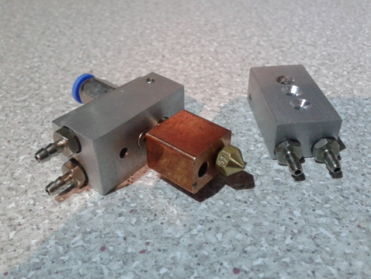
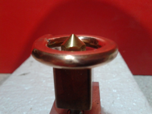
Getting tired of stearing at datasheets I have spent some time in the workshop and have started with a water-cooled hotend and an attempt to make a Berd type air ring to cool the freshly extruded plastic. I am not happy that I have enough height between the heater block and the tip of the nozzle to fit the Berd ring in so I will investigate using an arc of air jets each side. Some bits below for hotends and an air ring (no holes drilled yet)
Mike
|
Re: Hot Delta Build Log February 02, 2017 11:42AM |
Registered: 8 years ago Posts: 312 |
|
Re: Hot Delta Build Log February 03, 2017 03:59AM |
Registered: 12 years ago Posts: 1,450 |
|
Re: Hot Delta Build Log February 03, 2017 07:26AM |
Registered: 12 years ago Posts: 1,450 |
Bummer!! I have to abandon my plans to make the supporting body of laser cut acrylic. The inner body was to be top and bottom plates of 10mm Perspex Acrylic) and 3 sides of 3mm perspex with an outer wall also of 3mm Perspex. This is the construction - less the outer walls, of my existing Delta.
I have just spoken to somebody that I trust on these things and he told me that acrylic would work fine up to 80°C to prove a point but in a year or two it would no longer be tickety-boo if I wanted to use it to do serious printing.
Since the plan for the inner parts still look good, I now plan to make top and bottom plates of 6mm aluminium and a twin walled riveted aluminium structure for three sides of the box. The door will remain in 3mm Perspex. The build volume will also go down to 150mm diameter by 180mm height - the same as the Fisher. This is to use existing aluminium stocks but also because it fits 90% of the things I print. One saving grace of this idea is that the enclosure heater can be organised much like the heater in a fan oven.
Mike
|
Re: Hot Delta Build Log February 04, 2017 03:49AM |
Registered: 8 years ago Posts: 312 |
|
Re: Hot Delta Build Log February 04, 2017 04:09AM |
Registered: 8 years ago Posts: 5,232 |
|
Re: Hot Delta Build Log February 07, 2017 12:31PM |
Registered: 12 years ago Posts: 1,450 |
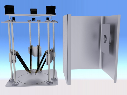
Many bits ordered but little visible progress beyond cutting some aluminium sheet. Basic design as shown below - the major bits omitted include the leadscrews as Turbocad freezes in fear if presented with a 4 start screw to render. The fan is visible on the side of the enclosure, heaters will also go under the baffle but have not yet been worked out.
As far as possible I am trying to keep to parts I have built or purchased before to avoid having the project grinding to a halt because something that obviously would work failing to do so.
Major decisions not yet made include if the leadscrews need bearings? Top and bottom? Thrust bearing? What kind of coupling? What king of extruder? Bowden or Zesty Nimble (possibly two???) Will the extruder and filament feed line need their own supply of cooling air?
Etc., etc., etc..
Mike
Edited 1 time(s). Last edit at 02/07/2017 02:52PM by leadinglights.
|
Re: Hot Delta Build Log February 08, 2017 09:34AM |
Registered: 8 years ago Posts: 312 |
Hey Mike, progress!
Cooling the filament and extruder, I think it is better to limit the amount of cooling air that is shot into the chamber.
That way you get the most consistent temperature at the print bed level. Because it might just be that you want to test with no cooling at all going into the print. If you are cooling the filament and extruder, you cannot help but add cooling to the print.
Unless. hmm.
What if you make a smaller chamber on the effector that is fed cooling air from outside and blows back out via a tube that also feeds the filament in? Way too complex.
Lykle
|
Re: Hot Delta Build Log February 08, 2017 01:16PM |
Registered: 12 years ago Posts: 1,450 |
Indeed hmm,
If there is an air supply for an air ring, more air sent along a tube around the filament (either Bowden or just a conduit if Nimble extruders or similar) also the water pipes for cooling the hot end could all be contained in a very thin loose tube which would take the exhaust air and keep the incoming bits insulated.
Mike
Edited 1 time(s). Last edit at 02/08/2017 01:16PM by leadinglights.
|
Re: Hot Delta Build Log February 11, 2017 08:15AM |
Registered: 12 years ago Posts: 1,450 |
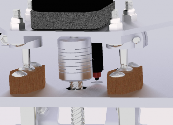
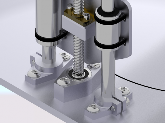
Kept away from the workshop by the cold but I have been doing some calculations on the thermal expansion of the working bits and the enclosure and I think it is necessary to make provision for expansion. When the chamber, which is made from aluminium sheet, and the rods which are made of stainless steel, are both heated from room temperature to 80°C, the difference in their expansions will be a little over 0.3mm. Trying this out with odd scraps of metal, the rods can be expected to bow by up to 0.7mm at the center - this is not good. My plan is to allow the rods to slide up and down in close fitting bushes and to carry the leadscrew and stepper motors with them. Picture below shows the top and bottom plates with rods fixed to the bottom and sliding in bushes (brown) made from Carp brand Tufnol.
I make no apology for the fussy detail in the renderings but the leadscrew was a challenge that I could not leave unmet. Turbocad is hard to use and this was not so much an example of polishing a turd but polishing with a turd.
Mike
Edited 1 time(s). Last edit at 02/11/2017 09:54AM by leadinglights.
|
Re: Hot Delta Build Log February 11, 2017 01:54PM |
Registered: 8 years ago Posts: 312 |
Well, clearly the polishing worked as I don't see a turd anywhere.
Nice solution for the expanding rods. Certainly better than allowing the top to slide along the walls.
But I am interested in why you let them slide at the top? Why not mount them fixed at the top, where the motor also is and have them sliding in the bottom, away from the complexity of having the motor slide up and down as well?
Lykle
|
Re: Hot Delta Build Log February 11, 2017 02:55PM |
Registered: 12 years ago Posts: 1,450 |
Quote
Lykle
.......
But I am interested in why you let them slide at the top? Why not mount them fixed at the top, where the motor also is and have them sliding in the bottom, away from the complexity of having the motor slide up and down as well?
Lykle
You may have noticed the thinner (5mm dia) section of rod holding up the motor mounting plates, this also a thermal expansion thing but depends on whether the rods they send are all hard or only induction hardened on the surface.
Mike
Edited 1 time(s). Last edit at 02/11/2017 03:04PM by leadinglights.
|
Re: Hot Delta Build Log February 12, 2017 02:02AM |
Registered: 8 years ago Posts: 312 |
|
Re: Hot Delta Build Log February 12, 2017 03:13AM |
Registered: 8 years ago Posts: 5,232 |
Quote
Lykle
What is the expanded length difference?
Will this be something that can be absorbed by the flexible coupling at the stepper?
My thoughts were similar, but I imagined a hex shape on the screw shaft and couplings with a hex shape too. Gliding in and out while the heat rises ( no pun intended )
|
Re: Hot Delta Build Log February 12, 2017 06:10AM |
Registered: 12 years ago Posts: 1,450 |
The difference in expansion gives a difference in length of about 0.3mm, easily able to be accommodated by the coupling. I may use Oldhams type couplings as I have a few of these.
I am leaning back towards having the Tufnol blocks back on the top though as I haven't seen any problem with the motor plate moving up an down a bit.
Mike
I am leaning back towards having the Tufnol blocks back on the top though as I haven't seen any problem with the motor plate moving up an down a bit.
Mike
|
Re: Hot Delta Build Log February 13, 2017 12:10AM |
Registered: 7 years ago Posts: 154 |
I think ya'll are overthinking the part cooling thing a bit. A part at 190-250 getting hit with air at 50 is still cooling. As for cooling the heat-break, I hadn't considered that, but of all the enclosed printers running stock hot-ends, we don't see enough posts to suspect heat-creep issues. I'm 80% of the way enclosing my delta at the moment too, let you know how it goes if I finish first.
|
Re: Hot Delta Build Log February 13, 2017 03:54AM |
Registered: 12 years ago Posts: 1,450 |
Quote
clearlynotstefan
I think ya'll are overthinking the part cooling thing a bit. ....
Sorry, but that's just me. First I overthink, then I overcalculate, then I realize that both my thoughts and calculations are probably based on ideas that are complete doggy doo - so I build and test.
Quote
.... A part at 190-250 getting hit with air at 50 is still cooling. As for cooling the heat-break, I hadn't considered that, but of all the enclosed printers running stock hot-ends, we don't see enough posts to suspect heat-creep issues. I'm 80% of the way enclosing my delta at the moment too, let you know how it goes if I finish first.
I At 80°C there are likely to be more problems than at 50°C: Problems like the filament being too soft to be driven by the extruder, distortion of the printer caused by different expansion of different materials etc..
BTW, I save a secret agenda - although the target is 80°C and I would accept 60°C, what i would really like to get to is 100°C.
Mike
|
Re: Hot Delta Build Log February 13, 2017 11:02AM |
Registered: 8 years ago Posts: 312 |
|
Re: Hot Delta Build Log February 14, 2017 12:05PM |
Registered: 12 years ago Posts: 1,450 |
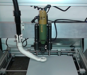
There are times when Murphy's law takes it's revenge for every time that you managed to avoid it. Today it is warm enough to venture into the workshop to cut the first serious metal for the new printer. It was also to be a test for my never before used CAM program and something a for the 3D printer/milling machine to earn its spurs on.
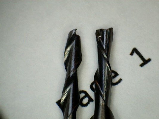
Although I took out a brand new 2mm end mill, I nevertheless checked it for sharpness under a microscope - Murphy's law avoidance remember, and double checked everything else. The first cut didn't seem too enthusiastic and it was obviously in deep distress at the second cut so I too it out and checked it - it was chipped. A second end mill from the same package fared no better and I looked very carefully for several minutes before I saw the problem.
In the picture below there is and old blunt 2mm end mill on the left and one of the new ones on the right
See if you can spot the problem.
Mike
|
Re: Hot Delta Build Log February 14, 2017 01:43PM |
Registered: 8 years ago Posts: 312 |
|
Re: Hot Delta Build Log February 15, 2017 01:04PM |
Registered: 9 years ago Posts: 1,159 |
|
Re: Hot Delta Build Log February 15, 2017 02:49PM |
Registered: 12 years ago Posts: 1,450 |
Quote
dougal1957
Easy just reverse the Spindle motor Rotational direction
Sadly no CW/CCW switch on the spindle

Mike.
|
Re: Hot Delta Build Log February 15, 2017 07:46PM |
Registered: 8 years ago Posts: 916 |
|
Re: Hot Delta Build Log February 27, 2017 04:48AM |
Registered: 12 years ago Posts: 1,450 |
Despite the delay, this project is not yet dead, but is only making slow progress against Murphy's Law. The first attempt to mill the carriages and effector on my converted 3D printer being thwarted by a contrary end mill but that hid the fact that the side play on the Proxxon rotary tool that I use as a spindle ensured that the workpieces looked like they had been chewed instead of being milled. The delay in getting started allowed me to discover a non-trivial error in my geometry that means that I have to increase the height of the printer which means that I can't use my old stocks of materials.
Hopefully this week will see at least one wheel back on track.
Mike
Hopefully this week will see at least one wheel back on track.
Mike
Sorry, only registered users may post in this forum.
