Testing the effects of microstepping and segmentation on print quality
Posted by dc42
|
Re: Testing the effects of microstepping and segmentation on print quality April 06, 2017 10:03AM |
Registered: 8 years ago Posts: 916 |
Quote
o_lampe
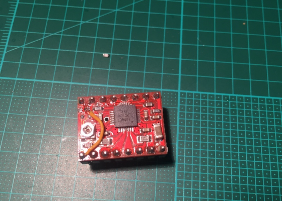
edit: The ROSC pin is already connected to the pad and grounded through the 010 resistor ( maybe not in full fast decay mode though )
[attachment 92712 A4988_ROSC.jpg]
O_lampe, you are a gentleman and a scholar. Many thanks for this info. Mine turned out to be the first variant. I've no idea how the firmware can measure the difference between 1 ohm and 0 ohms, but it sure seems to have made a difference. I used a wire so that I could connect it to +v if required, but just grounding it seems to have worked.
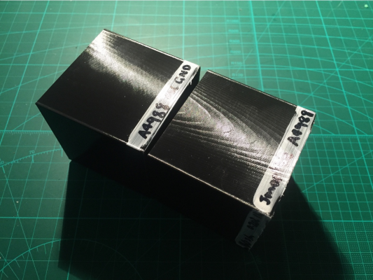
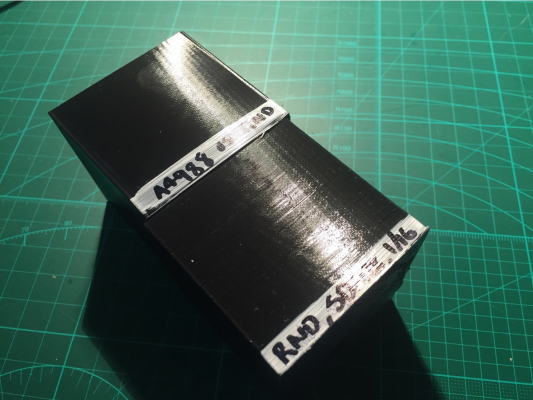
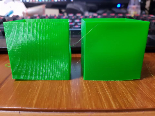
The cube on the bottom right is with a normal A4988 driver, the one on the top left has been hacked to ground the ROSC pin. It's quite a substantial difference.
The hacked A4988 driver is about as good as an unhacked SD6128 (both at 1/16). If the moire pattern wasn't there then you'd never notice the stripes.
So for the drivers A4988, DRV8825, SD6128, it's worth modding them to go into fast decay* if you can. The TMC2100 is good right out of the box, but has issues with torque.
* I don't know what you call grounding the ROSC pin on the A4988, but it gives better results, whatever it is.
|
Re: Testing the effects of microstepping and segmentation on print quality April 06, 2017 11:16AM |
Registered: 10 years ago Posts: 732 |
You switched your A4988 to mixed-decay mode on both raising current and falling current quadrant (PWM period 30 µs). You achieved it by shorting ROSC pin to ground.
When your pin was connected to the ground through resistor then the A4988 chip used slow decay in the raising current quadrant and mixed decay in the falling current quadrant. Provided that the removed resistor had resistance of 1 Ω, then the OFF time should have been 1/825 µs ... which does not make sense since it is less than the blanking time of 1 µs. 1Ω definitely looks like a wrong value for that resistor. I would expect either 0 Ω (i.e. shorted to ground) or at least 1650 Ω.
Thanks for posting the results. I think I have the same driver and if so then I will try this too.
Edit: Based on this schematic: [a.pololu-files.com]
The resistor you removed should have been 10 kΩ which corresponds to OFF time 12 µs, fast decay time 3.8 µs, blanking time always constant at 1 µs.
Edited 2 time(s). Last edit at 04/06/2017 11:57AM by hercek.
|
Re: Testing the effects of microstepping and segmentation on print quality April 07, 2017 09:51AM |
Registered: 10 years ago Posts: 732 |
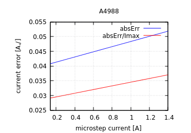
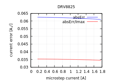
I was pointed to the microstepping problem on A4988 and DVR8825. Well, I did know that DVR8825 (which I did not use yet) has this problem but I did not know about A4988. A4988 must be switched to mixed decay mode for all the time. DVR8825 must be switched to fast decay all the time. If this is not done then you can expect microstepping errors in the range just below stepLength/2. For the stepper motors like I use: R ≅2 Ω, L ≅ 3 mH, U = 24 V, I ≅ 1.6 A. I would not really care about these errors for the smoothness of the walls. But I think they will make numerical calibration worse. Therefore it is worth to fix it. If you do it then the kind of errors you can expect are in the charts below (if you are using motors abut the same as I do - this depends on the stepper motor parameters):
The interesting part are the red lines. When you multiply them by 100 then you get the percentage which you can look up in the stepper driver microstepping tables and look how many microsteps you can be wrong because of current control using PWM (with mixed/fast decay) in the stepper driver. The tables will tell you that it is somewhere just below one microstep at 16 microstepping. Notice, these errors are valid after you switch the driver to the best decay mode. The drivers are not in the best mode by default. They do much much worse in the default mode ... as nebbian kindly figured out and let us all know
If you thing you see segmentation errors on your walls (as I did), well there is good chance you actually see the result of bad decay mode of your drivers.
The interesting part are the red lines. When you multiply them by 100 then you get the percentage which you can look up in the stepper driver microstepping tables and look how many microsteps you can be wrong because of current control using PWM (with mixed/fast decay) in the stepper driver. The tables will tell you that it is somewhere just below one microstep at 16 microstepping. Notice, these errors are valid after you switch the driver to the best decay mode. The drivers are not in the best mode by default. They do much much worse in the default mode ... as nebbian kindly figured out and let us all know

If you thing you see segmentation errors on your walls (as I did), well there is good chance you actually see the result of bad decay mode of your drivers.
|
Re: Testing the effects of microstepping and segmentation on print quality April 07, 2017 11:14AM |
Registered: 10 years ago Posts: 14,672 |
This issue with A4988s and A4982s has been known for several years. See [hydraraptor.blogspot.co.uk]. It's why the older Duet boards that use A4982 drivers have always had the Rosc pin shorted to ground.
Large delta printer [miscsolutions.wordpress.com], E3D tool changer, Robotdigg SCARA printer, Crane Quad and Ormerod
Disclosure: I design Duet electronics and work on RepRapFirmware, [duet3d.com].
Large delta printer [miscsolutions.wordpress.com], E3D tool changer, Robotdigg SCARA printer, Crane Quad and Ormerod
Disclosure: I design Duet electronics and work on RepRapFirmware, [duet3d.com].
|
Re: Testing the effects of microstepping and segmentation on print quality April 07, 2017 11:16AM |
Registered: 8 years ago Posts: 916 |
Quote
hercek
Edit: Based on this schematic: [a.pololu-files.com]
The resistor you removed should have been 10 kΩ which corresponds to OFF time 12 µs, fast decay time 3.8 µs, blanking time always constant at 1 µs.
I just found that resistor on my bench (not easy, let me tell you!!) and measured it. Voila, 9.96k.
Those graphs are interesting. I haven't tested this directly, but I had the feeling that 8825's were worse (a lot worse) than A4988's, if you were comparing either unmodded to unmodded, or modded to modded. The graphs suggest otherwise.
Looks like I'll have to pull my mini apart again. I'm getting pretty good at it by now. My desk is being swamped with cubes.
|
Re: Testing the effects of microstepping and segmentation on print quality April 07, 2017 12:35PM |
Registered: 10 years ago Posts: 732 |
The charts are computed based on model not measured experimentally.
The charts actually indicate that 8825 should be worse even for the motors I used if the driving current is less than about 1 A. Anyways the difference should not be big. If you are getting a big difference then your motor parameters are significantly different, or my model is wrong/tooSimplified, or something else is fishy.
At first look the charts actually make good sense. Notice that PWM frequency is fixed for 8825. Therefore the error slightly falls down when higher currents are used. The PWM frequency is variable for A4988 - it is falling with bigger currents(*), therefore the PWM error is raising with bigger currents.
(*) Because A4988 has fixed OFF time and variable ON time. The ON time is raising with higher currents. It takes longer time to rise current to higher values.
How the PWM error looks like for different motors depends especially on Tau = L/R of your motors, ... and the power source voltage.
The smaller the Tau (and the bigger the voltage) the higher the PWM error.
But with bigger Tau and smaller voltage (i.e. the combination which lowers PWM error) also drops the maximum motor speed you can precisely achieve. If you cross the maximum precise RPM then you will get much bigger errors than the errors from the PWM current control. This is because the errors are propagating from one PWM cycle to the next one and accumulating per one quadrant (electrical phase angle of 90°).
|
Re: Testing the effects of microstepping and segmentation on print quality April 07, 2017 12:41PM |
Registered: 10 years ago Posts: 732 |
|
Re: Testing the effects of microstepping and segmentation on print quality April 08, 2017 06:14PM |
Registered: 10 years ago Posts: 732 |
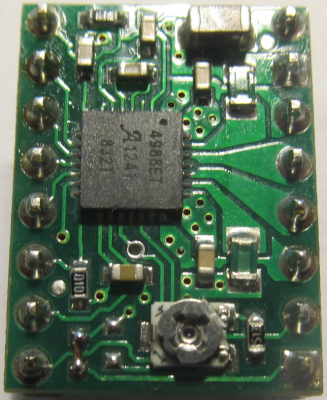
Ok; I have a4988 drivers too. I removed the resistor and connected ROSC pin directly to ground. I also replaced the resistor to the right of the potentiometer(*) which defines the stepper current. The original value was 20 kΩ and I repladced it with 51 kΩ. This makes the potentiometer much less sensitive and it is much easier to set the stepper current precisely.
(*) As you can see on the picture, the new resistor has number 513 on its package.
The results are as expected. The wall is significantly smoother. It is not visible well on the picture. Incredibly small details can be seen with good lighting. But the difference is very well felt when moving finger over the surfaces. And, as expected, the steppers are noisier now since the PWM frequency changed from about 35 kHz to about 22 kHz.
|
Re: Testing the effects of microstepping and segmentation on print quality April 12, 2017 10:50AM |
Registered: 8 years ago Posts: 916 |
Good stuff Hercek.
Here's some more data from a user on facebook with an MKS SBase (32 bit board, 8825 drivers)
Left print is printed at 0.202 layer height, right print is at 0.161.
From this I can see:
1) That he's using 20 tooth pulleys, so his steps/mm value is 80 or 160
2) That his drivers are not in the best decay mode
For him to get better prints, he should print at one of the following layer heights:
0.081, 0.161, or 0.243 mm.
After doing some research, his drivers are in mixed decay mode by default.
I'm starting to really wonder why no drivers ever seem to be in the best mode by default. Why should we always have to mod them???
|
Re: Testing the effects of microstepping and segmentation on print quality April 12, 2017 11:42AM |
Registered: 8 years ago Posts: 5,232 |
|
Re: Testing the effects of microstepping and segmentation on print quality April 12, 2017 07:06PM |
Registered: 8 years ago Posts: 916 |
Quote
o_lampe
Quote
I'm starting to really wonder why no drivers ever seem to be in the best mode by default. Why should we always have to mod them???
The best mode is a quiet stepper for some of us ( running and/or holding), others prefer the best torque.
Mixed decay is a compromise.
My SD6128's were quieter, and more accurate after modding.
|
Re: Testing the effects of microstepping and segmentation on print quality April 12, 2017 07:29PM |
Registered: 10 years ago Posts: 732 |
Well, he should fix first his platform adhesion problems. There he has about 2 mm error which will dwarf any surface errors. Just teasing :-)
The TMC2660 drivers on the Duet board seem to be pretty good. Unfortunately they cannot be put on a separate driver board for e.g. RAMPS since they need to be configured via SPI.
Community designed A4982 do not need any modification. Well, I'm not sure whether all boards using this driver use also the right parts. But for example this driver is set up properly for a 3D printer by default: [www.reprap.cc]
I have one piece and I checked it out. It was done right.
My guess is that the drivers we use were designed for stepper motors with significantly higher inductance and resistance. Or they were not really intended to properly hold the position for slow movement.
Despite all the simplicity A4988 (or A4982) are quite good. The mixed decay mode will use the fast decay part only when the current decreases the first PWM cycle. If the spec is not lying. I did not check this with oscilloscope. This is better than mixed decay mode of DRV8825 which will use the fast decay part in all PWM cycles when the current is decreasing. Again only info based on the docs. Anyway all low inductance/resistance motors will have problems because of blanking time. The driver chip designers could mitigate this quite easily by simply always inserting a fast decay segment of the same length than the blanking time just after the on time. This would prevent the error accumulation over PWM cycles when current is rising. It is simple to do and to use and the PWM ripple would be small.
As for as the increased PWM noise in fast decay mode. It does not bother me. The difference is well noticeable when the printer is not running but as soon as it is running then the other noises dwarf the PWM noise. Young people who hear high frequency better may differ in their opinion.
The fast decay PWM error bother me a bit more when calibrating. But error of about 1/16 of a step is not such a big deal.
|
Re: Testing the effects of microstepping and segmentation on print quality April 12, 2017 09:02PM |
Registered: 8 years ago Posts: 356 |
Quote
nebbian
Quote
o_lampe
Quote
I'm starting to really wonder why no drivers ever seem to be in the best mode by default. Why should we always have to mod them???
The best mode is a quiet stepper for some of us ( running and/or holding), others prefer the best torque.
Mixed decay is a compromise.
My SD6128's were quieter, and more accurate after modding.
you have to mod them ? dont you just have to turn the decay pot to go fast or mix ... Got a decay pot on my thb6128
|
Re: Testing the effects of microstepping and segmentation on print quality April 12, 2017 11:37PM |
Registered: 8 years ago Posts: 916 |
Quote
GroupB
you have to mod them ? dont you just have to turn the decay pot to go fast or mix ... Got a decay pot on my thb6128
Mine had solder jumper pads. A pot might be easier, but the pads are pretty easy to understand and use. Same same I think. If you've turned the pot to fast, then I think we're both in the same mode

|
Re: Testing the effects of microstepping and segmentation on print quality April 13, 2017 06:32AM |
Registered: 10 years ago Posts: 732 |
SD6128 should work well in mixed decay mode based on this document.
The chip has 1 µs blanking time and it always inserts 1 µs fast decay segment at the end of the PWM cycle when current is rising. And it inserts one full PWM cycle of fast decay when current is decreased. That looks like the best option for simple driver which does not require special configuration through some serial interface (SPI, I2C, ...).
The mixed decay mode looks like the best option for SD6128. Can people who have SD6128 confirm this?
|
Re: Testing the effects of microstepping and segmentation on print quality April 13, 2017 07:35AM |
Registered: 10 years ago Posts: 14,672 |
Quote
hercek
The TMC2660 drivers on the Duet board seem to be pretty good. Unfortunately they cannot be put on a separate driver board for e.g. RAMPS since they need to be configured via SPI.
The configuration via SPI means that you can change the decay mode in software. See the TMC2660 data sheet for details. The spreadCycle mode with the parameters that we set by default in RRF works well for almost everyone. According to the datasheet, it automatically determines the optimum length for the fast decay phase.
On the older Duets that used A4982 drivers, the drivers have always been configured in fast decay mode (right from the first Duets shipped in 2013) because of the known problems with mixed decay in some situations.
Edited 1 time(s). Last edit at 04/13/2017 07:38AM by dc42.
Large delta printer [miscsolutions.wordpress.com], E3D tool changer, Robotdigg SCARA printer, Crane Quad and Ormerod
Disclosure: I design Duet electronics and work on RepRapFirmware, [duet3d.com].
|
Re: Testing the effects of microstepping and segmentation on print quality April 13, 2017 02:41PM |
Registered: 10 years ago Posts: 732 |
dc42: I did not notice in the TMC2660 data sheet how one can set microstepping and maximum current without SPI.
Their (patent filled) spreadCycle mode looks interesting but I do not understand how it is better than e.g. THB6128 mixed decay mode.
SpreadCycle mode creates a nice small wave in the PWM signal by inserting the fast decay segment into the middle. That means that the first harmonic of the PWM will be significant. THB6128 inserts its 1 µs fast decay segment at the end of the PWM cycle after which there is immediately the ON phase. This results in smaller first harmonic ... which sounds better to me.
Of course THB6128 has a significant disadvantage compared to TMC2660. It cannot offset the whole PWM cycle trigger level properly. Therefore its average value will have slight error (somewhere in the range of 0.6% for my steppers - mostly negligible). It looks to me that if THB6128 would have some way to offset the threshold current where compactor (connected to the sense resistor) triggers then it could be as good as TMC2660. And if the offset would be settable using some analog voltage input pin, then it could be even be used without some serial configuration interface (i.e. on our small stepper driver PCBs and compatible with old controllers).
Of course, it is typically better when one can configure stepper driver from software.
A4982 driver do not have fast decay mode. Only slow or mixed decay. The default mixed decay does not kick in when the current is raising. But it can be set so that mixed decay is active all the time (I guess that is what you meant by "always configured in fast decay mode").
|
Re: Testing the effects of microstepping and segmentation on print quality April 13, 2017 02:51PM |
Registered: 10 years ago Posts: 14,672 |
Quote
hercek
A4982 driver do not have fast decay mode. Only slow or mixed decay. The default mixed decay does not kick in when the current is raising. But it can be set so that mixed decay is active all the time (I guess that is what you meant by "always configured in fast decay mode").
You are right of course, I was getting confused with the DRV8825. From the A4982 datasheet:
Quote
Low Current Microstepping. Intended for applications where the minimum on-time prevents the output current from regulating to the programmed current level at low current steps. To prevent this, the device can be set to operate in Mixed decay mode on both rising and falling portions of the current waveform. This feature is implemented by shorting the ROSC pin to ground. In this state, the off-time is internally set to 30 μs.
The older Duets have a 0 ohm resistor between ROSC and ground to use this feature by default.
Edited 2 time(s). Last edit at 04/13/2017 02:52PM by dc42.
Large delta printer [miscsolutions.wordpress.com], E3D tool changer, Robotdigg SCARA printer, Crane Quad and Ormerod
Disclosure: I design Duet electronics and work on RepRapFirmware, [duet3d.com].
|
Re: Testing the effects of microstepping and segmentation on print quality April 23, 2017 09:12AM |
Registered: 8 years ago Posts: 916 |
Sorry, only registered users may post in this forum.
