Folgertech Kossel 2020 kit, first try and success!
Posted by dlc60
|
Folgertech Kossel 2020 kit, first try and success! April 14, 2017 12:37AM |
Registered: 7 years ago Posts: 619 |
After building for about 3 weeks and spending about 3 hours configuring CURA2 to my Folgertech 2020 delta printer I tried a print, using the little 2 meters or so yellow PLA they sent with it. I got an X,Y,Z calibration cube from Thingaverse and printed it.
IT PRINTED!!!
First try!
The bed leveling worked.
My cut-in-half, spliced back together Bowden tube worked.
CURA 2.4.1 worked. (I still wonder why...)
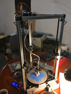
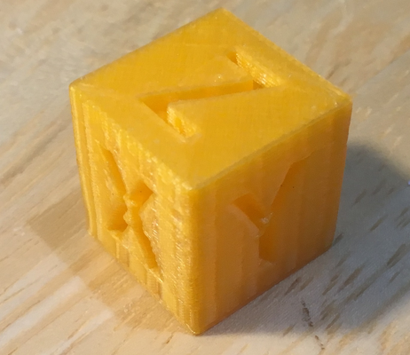
I have attached a pic of my Kossel printer and of my 20mm cube. So far I've printed two things, both in PLA and I am pleased.
Of course, it is too much to expect perfection. I measured my cube and it was 19mm x 19.5mm x 20.5mm (X,Y,Z). I obviously need to do some tuning. It is probably from inexact rod lengths and I'm hoping that I can fix it in firmware or CURA.
I measured the cube with calipers, it is actually a little better than I thought. X/Y/Z is 19.18mm x 19.13mm x 20.22mm.
My only hack, other than splicing my Bowden tube back together, was to put light weight springs between the adjacent rods to dampen down "bounce" or "rattle". The hot end cooling fan is so out of balance that it makes the entire end effector vibrate. That will need fixing. And eventually I will need an aluminum end effector when this one has an accident. I can never pass up hacking a kit to improve it, so if anyone has any ideas about how to "pimp" my Folgertech Kossel 2020, I am all ears.
My son was wowed by how fast it was compared to the Cartesian printers they have at school. I was just happy it worked!
Forcing myself to go to bed,
DLC
Edited 1 time(s). Last edit at 04/14/2017 12:57PM by dlc60.
|
Re: Folgertech Kossel 2020 kit, first try and success! April 15, 2017 01:53PM |
Registered: 7 years ago Posts: 619 |
More conversations with a delta printer noob.
Well, the initial success was, typically, beginners luck.
After that first run using the little bit of PLA Folger Tech sent, I tried two other brands of PLA and neither of them "stuck" the first layer outer line. The PLA either didn't come out, or curled up around the tip. I have been reading tons of "help me" posts and responses and fiddling with Z depths, bed and tip temperatures CURA settings and the like. Fun! It wouldn't be a hobby if everything worked perfectly, would it?
Anyway, the secret to success here, as with any engineering or building process is to keep notes on everything that you do. That is a hint for others...
Also, use use revision controls on your source, even if it is just keeping multiple copies. Don't lose anything. Change one thing at a time and look for the results. Calibration and tuning of a new "thing" requires patience and organization.
I have spent about 20 hours of tweaking, testing, and waiting to perfect my XYZ calibration cube. This involved tweaking the center-to-center rod length constant in the Marlin firmware to be 233mm instead of the absolutely perfect 240. This finally gave me a 20mm cube that was 20.09 x 20.01 x 20.03.
Hints for success on my Folger Tech Kossel 2020 using PLA:
Heat the bed, if you don't all the corners curl up. 60 C seems good for me.
Don't make the first layer thicker than the others, it often doesn't adhere. If you make it the same (say .2mm) then a bobble on that layer isn't catastrophe either.
CAREFULLY find your Z offset from the inductive sensor to the bed. This is super critical. Mine is -.4mm, it depends on how you installed that sensor.
Screw the nozzle all the way onto the heater block, THEN screw the heater block onto the cooled feed tube. This kept my Z height consistent.
Use the blue painters tape. PLA sticks very well to it. I only have the aluminum bed with tape on it, it seems to work fine.
If you don't have overhangs, in CURA 2.4, only use "support" "in contact with base" so you don't get support gunk in "holes" in middle of a wall you need to cut out.
ApparentlyTweakatZ gcode in CURA 2.4 needs set to change tip temperature back to 200 C after layer 2 every time you open a part. 215C is too hot to print the whole image with! Check to make sure that plugin is active!
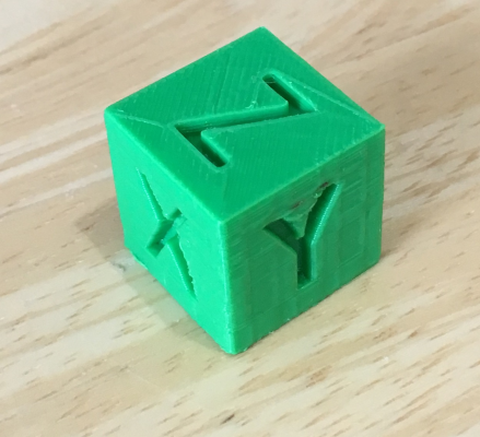
In the end, my 20mm XYZ cube is: 20.09 x 20.01 x 20.03.
I call success, time to move on. I've attached in image.
Hopefully this post is useful to another newcomer that has a Folger Tech Kossel 2020 kit built and is trying their first prints.
DLC
Edited 2 time(s). Last edit at 04/15/2017 04:28PM by dlc60.
|
Re: Folgertech Kossel 2020 kit, first try and success! May 03, 2017 08:07PM |
Registered: 7 years ago Posts: 5 |
I too just finished by first 3d printer, the Folger Kossel 2020.
I found it to be a fairly good kit, but the instructions had various errors, were ambiguous, or were simply out of date. For what its worth, I've attached my build notes in the hopes that it help or save time for others.
1) The user manual specifies the wrong length for some screws. Examples: one of the screws that mount the belt holder to the carriage is too long. Screws for mounting the effector are too short. The screws for attaching the extruder stepper to the acrylic are too long (I had to cut these). I ordered an assortment of extra M3 screws (Amazon). I didn’t need many but it was helpful.
2) The hot end wouldn’t fit into the recess hole on the plastic effector. I ended up ordering the aluminum effector and it worked great. Also it was not clear but the recess should go face down.
3) The nut pockets on the belt holder will strip out and not prevent the nut from rotating. Either glue the nuts to the holder or use a small slot screw driver to wedge the nut while tightening the screw.
4) Check your rod ends for ball to socket play. Pick the tightest ones.
5) I used one of the 2020 beams to make a glue-up fixture for the rods. Take a couple of 1” sections of the M3 rod, T-nuts, a couple of washers (Home Depot) and M3 nuts. This helped insure that all the rods were the same length. I glued up one rod at a time using Gorilla super glue gel. For what it’s worth, I used a mini cut-off saw (Harbor Freight) with an abrasive blade (Amazon) to cut the carbon fiber rods and the M3 rods.
6) If you follow the user manual instructions, the limit switches will not line up with the carriages. I flipped the acrylic “L” around and it worked much better. I also suggest getting some M3 washers (Home Depot) to put between the board and acrylic to provide clearance for the solder bumps and keep the board vertical.
7) The hot end mount fit snuggly around the hot end, but the mount was slightly thinner than the slot in the hot end. This resulted in excessive play. After putting the mount onto the hot end, I used a few of snug wraps of fine stranded uninsulated wire to fill the top gap. This eliminated the play.
8) If it is late at night and the Ramp 1.4 board holes do not line up with the holes in the acrylic, simply flip the acrylic over. The holes are not symmetric.
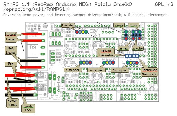
9) Which way should the stepper cables be plugged into the Ramp 1.4 board? The picture in the user manual shows the red wire on the left, the instructions say red goes on the right. Which is correct? The attached Board drawing shows the plug color order that worked with the firmware. (…and yes the brass extruder tip will put a good divot in an aluminum heater bed if you get it wrong.) Note: the extruder stepper plug orientation is different than the other steppers.
10) Also, the user manual section for the Ramp 1.4 board is incorrect as to where to plug in the thermistors. The locations in the Board diagram worked with the firmware.
11) Three pin connector supplied had different colors than in the user manual. The attached Sensor drawing shows what I used to go with the Board diagram. I used heat shrink tubing instead of the Kaplon tape to protect the resistors and solder joints.
12) The wiring supplied with extruder stepper motor barely reaches the controller board. Mount the extruder next to the tower nearest the stepper plug (instead of centering it on the beam).
13) DO NOT cut the Bowden tube in half. At most take off a few inches, I used the length as supplied after trimming off the ends square with a razor blade.
14) The user manual is not clear on which way the fan is supposed to blow. I believe it should blow cool air towards the hot end, as opposed to pulling warm air from the hot end.
15) Look at the original Rev-A delta user manual for: how to set the current limits of the stepper drivers (I used 0.500v), assembling the spool holder (it mounts on a top 2020 beam), and getting the X/Y/Z tower orientation correct.
16) If you try to compile the firmware with the latest Arduino IDE software you will get an error message. The provided firmware is based on an older version of Marlin and you will need to use an older version of the Arduino IDE. I found that Arduino IDE version 1.0.6 worked.
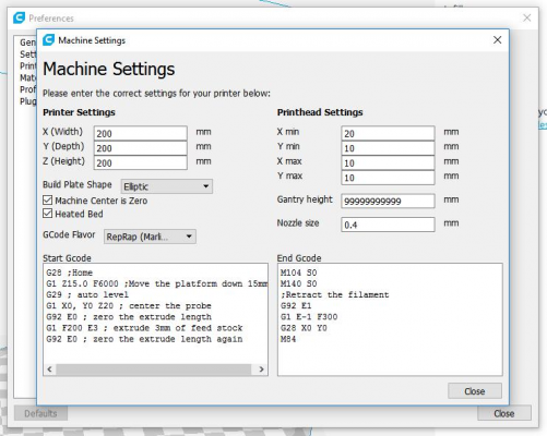
17) The user manual instructions show configuring an older version of Cura. I found the following “custom printer” settings worked with the newer version of Cura - version 2.5.0.
18) The following is what worked with Pronterface
Regards,
Bradb
|
Re: Folgertech Kossel 2020 kit, first try and success! May 04, 2017 11:34PM |
Registered: 7 years ago Posts: 619 |
I saw every one of those things you mentioned. Either you have a great memory or you wrote down all of the wrong steps and your corrections. I have some comments on your list of things. I too think that this is a pretty good kit. There are some quality bits in there, like a genuine Arduino Mega board and RAMPS controller. The Stepstick stepper drivers are quality as well.
1: The manual spec's the wrong screws all over the place. Only a few were correctly identified. Fortunately they give you a boatload of spare screws to work with, so this isn't much of a problem.
2: I sanded out the Bowden tube hole in the end effector and the snugged in nicely. Also had to sand the fan/sensor mount slot a little to get around the hot end feeder tube.
3,4: yup.
5: I too used a jig to cut all of the carbon fiber tubes. I have a razor saw that I use for modeling which cut them nicely. I used the included super glue, it is GOOD super glue!
6: I didn't think of that. I glued zip tie plastic to the tops of the carriages to fix this problem. BTW, these d*mn screws were too long too. Nylon washers to the rescue.
7: I had no problems here. I do note that you should screw the nozzle into the heater and then screw the heater onto the feeder tube. It stays a little tighter that way.
8: No issues here
9: Oh yeah. I guessed and got it wrong, plowed into the aluminum deck. Later I discovered it was because for some reason the firmware says to reverse these steppers. Someone just got lazy and fixed a bad graphic by changing the firmware. And didn't tell anyone else about it. Stupid.
10: When my board didn't heat I Googled it, every one else chose the middle thermistor for the bed heater. Ta da! Sheesh.
11: Yup.
12: My kit had an extra long cable that easily reached for the filament stepper easily.
13: I cut mine, they sent me another 25" piece, and I bought another two meters in case they were slow, Amazon and Folger Tech tied getting to my mailbox.
14: Correct, blow to the fins. I made a "thing" that focused that fan on the fins and not the board. Then made another thing that replaced the fan mount and inductive sensor (ick) completely with a zero offset mechanical switch auto bed leveler. Works way better.
15: I exchanged email with FT tech support Dustin Corbin, he said he set his steppers to .8V and 1.1 on the extruder stepper. I set all of mine to .82V and nothing overheats and all are quite strong.
16: You don't need to use old Arduino compilers, just fix the errors, and it will compile. There are a couple of duplicate defines that aren't used anywhere, so just delete one, and rename the SD card variable to not conflict with the system libraries. All good then.
17: I started with CURA 2.4, but have since moved on to Simplify3D, it has a lot more tunable knobs and once you get used to it, is very powerful.
DLC
|
Re: Folgertech Kossel 2020 kit, first try and success! June 09, 2017 12:45AM |
Registered: 7 years ago Posts: 5 |
As a follow up...
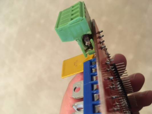
After only a handful of prints, the bed heater quit working... It turns out that the power connector on the RAMPS 1.4 board was fried. It appears the bed heater can pull more current than the green power connector can reliably handle. FYI - it was the internal pin/socket of the connector that failed, not the wire screw clamp.
A little digging on line will show this is a fairly common problem. Some folks simply remove the green connector and solder the power wires directly to the Ramps board. I was not convinced the P55NF06L FET on the RAMPs board could handle the current without at least a heat sink. One could upgrade the FET and squeeze in a small heat sink, but how much current would the blue connectors and board traces handle?
So... I've replaced the fried power connector on the RAMPs board with an identical connector (Amazon), but am adding a separate "heat bed power module" board (Amazon) to handle the current for the just the bed. It appears the module should be able to handle up to 25Amps.
Sorry, only registered users may post in this forum.
