New Build. Design Advice
Posted by WithTime
|
New Build. Design Advice April 24, 2017 07:20PM |
Registered: 7 years ago Posts: 2 |
Hey Guys,
Long time lurker,
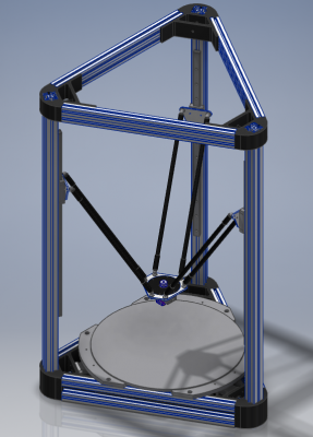
Over the last 2 weeks I've been been going through various iterations of a design for a delta printer.
I originally started working on a hexagonal shaped delta, however the lack of available metal corners for delta printers. I did get a quote on getting my corners machined out of billet aluminium, however it worked out to be almost as expensive as all other parts combined, so that is a no go.
I have been going through a number of builds on this forum and others, taking a fair amount of influence from DjDemonD and dc42 printers as well as dc42's FR4 effector.
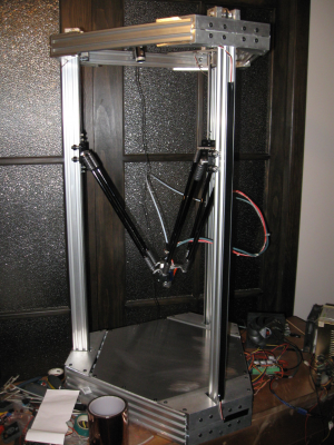
Therefore this is what I am up to so far.
- 3030 uprights,
- Robotdigg metal corners,
- 800-900 mm tall,
- Haydn's magnetic ball joints,
- 60 mm arm spacing,
- 330 - 345mm heated bed,
- 300mm 500 W 240 VAC heated bed,
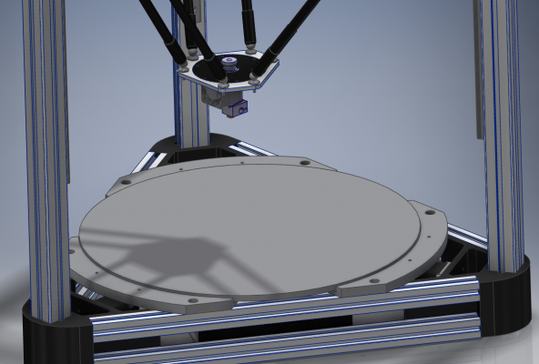
I currently have a 345 mm x 6.35mm (1/4") thick ATP-5/Alca 5 aluminium tooling plate and a 300mm 500 W silicone heated bed which I was given.
-This will give me an ~22.5mm border around the heated bed, do you thick this distance will cause any issues? O should I either get a new heated bed or cut the bed down to 330mm?
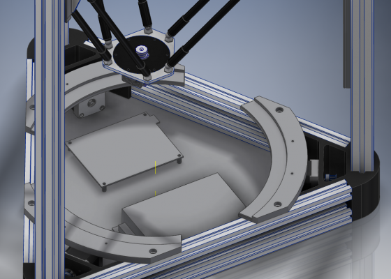
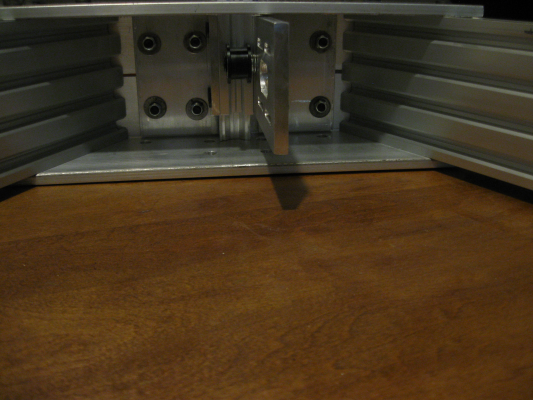
Last photo shows how the 24 VDC power supply as well as a Duet wifi will fit, However I would most likely use a Duet ethernet board, Wifi is not the best where my printer is going to be placed. However I do have an ethernet cable available.
I am planning on making the effector and carriages from 4mm aluminium sheet, With the circle on the inside of the effector being a 2mm thick FR4 with intergrated connectors top and bottom.
Just after a bit of constructive criticism, I am a bit to close to the subject.
-Mitch
Edited 1 time(s). Last edit at 04/24/2017 07:20PM by WithTime.
|
Re: New Build. Design Advice April 25, 2017 02:57AM |
Registered: 9 years ago Posts: 483 |
Dimensions are quite close to my delta.
Here are my recommendations:
Here are my recommendations:
- There isn't any need to cut the bed down and you can always make the arms longer if you need to make a larger print. The 300mm heat pad will work fine.
- Angle the balls on the carriages so the arms can go to 90 degrees with no interference.
- My arm length is 376mm with an arm radius of 196mm.
- Put the motors and electronics on top. It's much simpler to wire and to work on.
|
Re: New Build. Design Advice April 25, 2017 02:58AM |
Registered: 10 years ago Posts: 14,672 |
Looks good! A few suggestions:
- Don't make it too hard to get at the USB connector and the SD card on the Duet. What is the separation of the two lower horizontal extrusions using the 3030 metal corners? If it's 25mm or more, then you can mount the end of the Duet Ethernet between the extrusions, so that the Ethernet connector, SD card socket and USB connector are accessible from the outside.
- Plan what sort of bed probe you will use. I used an IR probe on my delta for a long time, but nozzle-based probing is better for a delta. The PCB effector we have developed has built-in nozzle contact sensing. Other options include a hot end mount incorporating a piezo sensor (see DjDemonD's thread), and FSRs under the bed.
I don't think a 22.5mm unheated border around the edge of the bed will be a problem, given the thickness of the plate. I have a 15mm unheated border around the edge of mine.
Large delta printer [miscsolutions.wordpress.com], E3D tool changer, Robotdigg SCARA printer, Crane Quad and Ormerod
Disclosure: I design Duet electronics and work on RepRapFirmware, [duet3d.com].
|
Re: New Build. Design Advice April 25, 2017 09:00AM |
Registered: 8 years ago Posts: 3,525 |
To be fair it looks great. +1 for mounting the duet board with its connector/leds accessible. Mine's at the front of the machine and it has been very easy to work on when needed. If designing or modding a front panel, Davids one is very good, consider designing a little flap to cover the erase button from the outside to avoid accidentally pressing it (it happens quite a lot) and ensure there is enough relief around the panel near the erase button, I pressed mine just jiggling the board into place. Its not a big deal to write the firmware back to it but it will save you time. I would say just leave a small hole over the erase button so you need to put a paper clip into it but unless the board is screwed firmly down it can move forwards and press the button accidentally.
Agreed on the heater I wish I'd left a bit more gap at the edges between silicone heater and bed, you rarely print anything that close to the edge anyway (and in any case it will still get plenty hot), and it makes seating/mechanically levelling the bed easier.
Arm length is tricky as most of the simulators get you quite close but not very close, and if ordering Haydens arms, you don't really want to have to cut them and extend them (although you could) as they are so nice. Mine are 360mm, with 330mm horizontals, and the bed is 330 of which almost all (except right by the tower bases due to effector size) is usable. Go slightly longer with the arms than you think you'll need the downside is just a few cm's of height you are almost never going to need. Your bed is within the horizontals so you should have no problem reaching and printing on any part of the bed.
Interestingly even with tooling plate, if you tell the firmware your bed is only 200mm not 300mm diameter and then re-calibrate your autocalibration accuracy will jump up. If you go to 100mm it will be very well calibrated potentially. I was getting a 0.006 deviation with just 80mm diameter when I was testing a 100x100mm sample printing surface. So I have now 3 macros called from within bed.g 100mm, 200mm and 300mm diameter, and I just comment out/in the one I want depending on what I'm printing, since its not often you will really use the 300mm+ width.
Metal effector and carriages are a big plus - looking forward to trying these PCB ones. Also consider raising your hot end so that just the heater block is protruding below the effector, it does make a difference (and frees up a little z-height those longer arms took up), and its the last thing I am going to do to my machine (for now ).
).
I'm a bit 50:50 on the bed clamps, sometimes I use them sometimes not.
Edited 2 time(s). Last edit at 04/25/2017 09:26AM by DjDemonD.
Simon Khoury
Co-founder of [www.precisionpiezo.co.uk] Accurate, repeatable, versatile Z-Probes
Published:Inventions
Agreed on the heater I wish I'd left a bit more gap at the edges between silicone heater and bed, you rarely print anything that close to the edge anyway (and in any case it will still get plenty hot), and it makes seating/mechanically levelling the bed easier.
Arm length is tricky as most of the simulators get you quite close but not very close, and if ordering Haydens arms, you don't really want to have to cut them and extend them (although you could) as they are so nice. Mine are 360mm, with 330mm horizontals, and the bed is 330 of which almost all (except right by the tower bases due to effector size) is usable. Go slightly longer with the arms than you think you'll need the downside is just a few cm's of height you are almost never going to need. Your bed is within the horizontals so you should have no problem reaching and printing on any part of the bed.
Interestingly even with tooling plate, if you tell the firmware your bed is only 200mm not 300mm diameter and then re-calibrate your autocalibration accuracy will jump up. If you go to 100mm it will be very well calibrated potentially. I was getting a 0.006 deviation with just 80mm diameter when I was testing a 100x100mm sample printing surface. So I have now 3 macros called from within bed.g 100mm, 200mm and 300mm diameter, and I just comment out/in the one I want depending on what I'm printing, since its not often you will really use the 300mm+ width.
Metal effector and carriages are a big plus - looking forward to trying these PCB ones. Also consider raising your hot end so that just the heater block is protruding below the effector, it does make a difference (and frees up a little z-height those longer arms took up), and its the last thing I am going to do to my machine (for now
 ).
).I'm a bit 50:50 on the bed clamps, sometimes I use them sometimes not.
Edited 2 time(s). Last edit at 04/25/2017 09:26AM by DjDemonD.
Simon Khoury
Co-founder of [www.precisionpiezo.co.uk] Accurate, repeatable, versatile Z-Probes
Published:Inventions
|
Re: New Build. Design Advice April 25, 2017 06:39PM |
Registered: 8 years ago Posts: 356 |
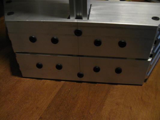
There is a way to make low price metal corner without having them machined if you really want to, Use L shape alu bar cut at 60 degree with a couple of hole thats it (require a miter saw or a tablesaw with sled or get them to a machinist) I did it on mine its kind of a hexagone but with only 3 tower , I made the corner so large that the triangle form became a hexagon, having them that way help them to resist the force on all side. I went little overboard with .25" but they beat the robotdigg easy., plus when I start my design there were no metal corner on the market...So I had to design one that dont break the bank ( aka not require a machinist shop).
Here an example of the kind of corner im talking about :
Here an example of the kind of corner im talking about :
|
Re: New Build. Design Advice April 26, 2017 05:08AM |
Registered: 7 years ago Posts: 2 |
Cheers guys,
Thanks for the great advice,
I am planning on having the duet board accessible from the outside, in the spot at the moment purely for a visual of size.
With the 3030 metal corners, it uses 3030 for the uprights and 2020 extrusion for the sides. Once it arrives ill have to see how much space is available.
I have the delrin rod ends and the ball studs from Haydn, I didn't get premade arms. I am basically looking at using 360-380mm. My horizontals are 390mm.
Currently for bed levelling I am tossing up between using DjDemon's Piezo mount.
Does anyone have any experience with the IGUS N series slides, particularly the 40mm. I have been offered a few 600mm lengths for free so am considering just trying them out.
I'm looking forward to the wiring. Its very close to what I do for work.
I have had a 3d printer for about 3 years now so not brand new. Just a Prusa i3 clone. Been recently using it for not just as hobby but also for work, prototyping radio mounts/engine intakes, engine exhaust valves and then getting them machined out of aluminium/steel. Therefore looking to upgrade to something a lot more accurate/ slightly bigger bed.
Thanks for the idea Group B. Neat solution.
Thanks for the ideas on the effector. Will looking into making it from some scrap 2024-T3 0.125" aluminium from work and bending the ball stud mounts down 30-45 degrees.
|
Re: New Build. Design Advice April 26, 2017 05:51AM |
Registered: 9 years ago Posts: 1,159 |
With Haydn's Delrin ends you don't need to bend anything as they will go past the 90 Degree point easily saves a lot of machining 
I suspect the Robotdigg corners if there anything like the 2040 ones will take 20x40 at one end and 20x60 at the other (I am putting my 20x60 ones with the motors etc at the top of the frame where there will be mor room and will be more accessible rather than under the bed which in my case is 6mm thick cast tool plate 360mm diam with a 330 diam silicon heater under it.
as for the IGUS rails I have some samples that they provided and would use them if it wasn't going to cost around £400 for a set of 3 at 800mm long?
Doug
|
Re: New Build. Design Advice April 26, 2017 06:09AM |
Registered: 8 years ago Posts: 3,525 |
I think with the choice of positions for electronics etc... It depends on how big the machine is and whether it's going to be on a bench or on the floor.
The piezo won't disappoint once tuned its very convenient and it seems as accurate as the alternatives without the offsets and deploying etc... That being said the mod with the ir sensor and a rod to probe the bed and trigger the IR is a clever idea. It still needs a servo or something to stow and deploy it.
Edited 1 time(s). Last edit at 04/26/2017 06:25AM by DjDemonD.
Simon Khoury
Co-founder of [www.precisionpiezo.co.uk] Accurate, repeatable, versatile Z-Probes
Published:Inventions
Sorry, only registered users may post in this forum.
