Frustrating calibration issue
Posted by Moriquendi
|
Frustrating calibration issue October 19, 2017 01:02PM |
Registered: 9 years ago Posts: 487 |
I'm currently trying to solve a very frustrating calibration issue with my kossel mini.
Two points around the perimeter of the print bed are out of alignment by 0.8mm. If we call the axis X, Y and Z counterclockwise from front left with; point A between X and Y, B between Y and Z, and C between Z and X. Point A and B are reading 0.8mm low and I cannot fathom why. All other points are within 0.08mm of each other, ball joints are equally spaced within 0.1mm and arm lengths are equal within 0.1mm. The bed is square to the towers to the best of my ability to measure. The results are consistent over multiple probings.
Has anyone run into something like this before?
Idris
{Precision Piezo} Accurate, repeatable, versatile z-probe plus piezo discs, endstop cables, pt100, 50w heaters.
|
Re: Frustrating calibration issue October 19, 2017 01:29PM |
Registered: 8 years ago Posts: 165 |
|
Re: Frustrating calibration issue October 19, 2017 03:24PM |
Registered: 9 years ago Posts: 487 |
I'm not familiar with tower angle corrections and I'm not sure the version of smoothieware I'm currently using supports it, I tried using DC42s offline calculator but things got worse rather than better. I'll update smoothieware in the morning and see whether things improve.
Idris
{Precision Piezo} Accurate, repeatable, versatile z-probe plus piezo discs, endstop cables, pt100, 50w heaters.
Idris
{Precision Piezo} Accurate, repeatable, versatile z-probe plus piezo discs, endstop cables, pt100, 50w heaters.
|
Re: Frustrating calibration issue October 19, 2017 04:45PM |
Registered: 10 years ago Posts: 14,672 |
If using my calculator makes the calibration worse, that usually means that you are entering the height errors with the wrong sign. A lot of users seem to use that mistake. Perhaps it's because the firmware they are using reports them in the opposite sense to how the height errors defined in the calculator.
Large delta printer [miscsolutions.wordpress.com], E3D tool changer, Robotdigg SCARA printer, Crane Quad and Ormerod
Disclosure: I design Duet electronics and work on RepRapFirmware, [duet3d.com].
Large delta printer [miscsolutions.wordpress.com], E3D tool changer, Robotdigg SCARA printer, Crane Quad and Ormerod
Disclosure: I design Duet electronics and work on RepRapFirmware, [duet3d.com].
|
Re: Frustrating calibration issue October 19, 2017 05:13PM |
Registered: 9 years ago Posts: 487 |
I thought that might be the case. I'm pretty sure at this point that I've got a geometrical error. This error came up because I disassembled and measured/set all the ball joints trying to eliminate and earlier offset, I think now that it may have been masking this problem.
Having now disassembled and reassembled a couple of times I'm seeing a slightly different pattern
A and B are still worst but C is out too now.
Idris
{Precision Piezo} Accurate, repeatable, versatile z-probe plus piezo discs, endstop cables, pt100, 50w heaters.
Having now disassembled and reassembled a couple of times I'm seeing a slightly different pattern
Recv: initial Bed ht is 261.587494 mm
Recv: center probe: 0.0000
Recv: X-69.2800 Y-40.0000 Z13.7699
Recv: X69.2800 Y-40.0000 Z13.8074
Recv: X0.0000 Y80.0000 Z13.9074
Recv: X0.0000 Y0.0000 Z13.7949
Recv: X69.2800 Y40.0000 Z13.0074
Recv: X-69.2800 Y40.0000 Z13.6449
Recv: X-0.0000 Y-80.0000 Z13.2199
Recv: max delta: 0.762500
A and B are still worst but C is out too now.
Idris
{Precision Piezo} Accurate, repeatable, versatile z-probe plus piezo discs, endstop cables, pt100, 50w heaters.
|
Re: Frustrating calibration issue October 20, 2017 03:42AM |
Registered: 6 years ago Posts: 20 |
I have similar issues with my Tevo LittleMonster delta. That's why I started using piezo sensor, to negate any hotend tilting and BLTouch errors. Thanks for the wonderful boards.
You can find a smoothie branch with LSQ support built in, made by purplefabr (https://github.com/purplefabr/SmoothiewareLSQ), you use it to get the M666 and M665 from the config override and put those back in the latest edge version to get the grid compensation.
The results are exactly the same as escher3d's online tool, so the implementation is good.
In my case I have 3 low spots at 120 degrees apart, 8-10 degrees clockwise from tower centers, super weird.
When probing the movement is mostly vertical and I tend to get under 50 micron variation accross all the bed surface, when printing the movement is mostly horizontal and I get over 100-150 micron lower spots, maybe joints are binding, maybe belts are too loose or too tight, haven't figured out yet...
Edited 1 time(s). Last edit at 10/20/2017 03:43AM by executivul.
|
Re: Frustrating calibration issue October 20, 2017 06:17AM |
Registered: 10 years ago Posts: 14,672 |
Assuming you have calibrated delta radius and endstop corrections, the standard pattern you get if the tower positions are slightly wrong is ridges midway between two pairs of towers and a valley between the third pair; or vice verse (2 valleys and 1 ridge). However, the pattern you get if the bed is tilted relative to the towers isn't much different.
Large delta printer [miscsolutions.wordpress.com], E3D tool changer, Robotdigg SCARA printer, Crane Quad and Ormerod
Disclosure: I design Duet electronics and work on RepRapFirmware, [duet3d.com].
Large delta printer [miscsolutions.wordpress.com], E3D tool changer, Robotdigg SCARA printer, Crane Quad and Ormerod
Disclosure: I design Duet electronics and work on RepRapFirmware, [duet3d.com].
|
Re: Frustrating calibration issue October 20, 2017 12:55PM |
Registered: 9 years ago Posts: 487 |
I've updated the firmware and run through the calculator a few times and things have improved somewhat
Recv: initial Bed ht is 261.612488 mm
Recv: center probe: 0.0000
Recv: X:-69.2800 Y:-40.0000 Z:1.7500
Recv: X:69.2800 Y:-40.0000 Z:1.7625
Recv: X:0.0000 Y:80.0000 Z:1.7125
Recv: X:0.0000 Y:0.0000 Z:2.0000
Recv: X:69.2800 Y:40.0000 Z:2.2750
Recv: X:-69.2800 Y:40.0000 Z:2.2750
Recv: X:-0.0000 Y:-80.0000 Z:2.2625
Recv: max delta: 0.524994
But no matter how many times I run through I can't improve beyond a delta of 0.5. What kind of error results in low measurements between towers?
Idris
Edited 1 time(s). Last edit at 10/20/2017 01:00PM by Moriquendi.
{Precision Piezo} Accurate, repeatable, versatile z-probe plus piezo discs, endstop cables, pt100, 50w heaters.
|
Re: Frustrating calibration issue October 20, 2017 01:59PM |
Registered: 10 years ago Posts: 14,672 |
We have a wiki page on this at [duet3d.com]. Obviously effector tilt won't affect your Z probe reading if you are using a piezo to detect nozzle contact with the bed, but it is still indicative of geometric errors.
If you were using a Duet, you would have the benefit of least squares auto calibration permanently built into the firmware, and a graphical display of the height map.
Large delta printer [miscsolutions.wordpress.com], E3D tool changer, Robotdigg SCARA printer, Crane Quad and Ormerod
Disclosure: I design Duet electronics and work on RepRapFirmware, [duet3d.com].
If you were using a Duet, you would have the benefit of least squares auto calibration permanently built into the firmware, and a graphical display of the height map.

Large delta printer [miscsolutions.wordpress.com], E3D tool changer, Robotdigg SCARA printer, Crane Quad and Ormerod
Disclosure: I design Duet electronics and work on RepRapFirmware, [duet3d.com].
|
Re: Frustrating calibration issue October 20, 2017 02:55PM |
Registered: 9 years ago Posts: 487 |
Thanks, I'll read through that, any suggestions for where to look for this particular pattern of errors?
When I bought my Smoothieboard it wasn't clear who was supporting deltas better and at the time I think the documentation for smoothie was better. Now it seems that Smoothie is broadening out from 3D printers while Duet has remained focused. If I were buying today I might well choose Duet over Smoothie.
Idris
{Precision Piezo} Accurate, repeatable, versatile z-probe plus piezo discs, endstop cables, pt100, 50w heaters.
|
Re: Frustrating calibration issue October 20, 2017 05:45PM |
Registered: 10 years ago Posts: 732 |
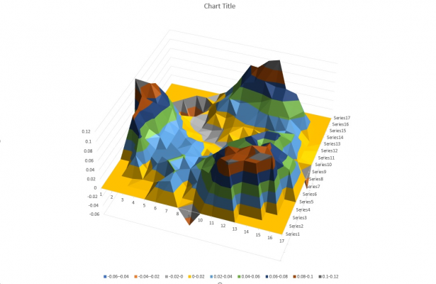
The pattern is quite symmetrical. Lower at the towers. Higher between them. I would not expect symmetrical pattern from a tilted bed.
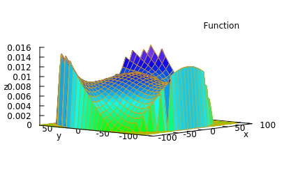
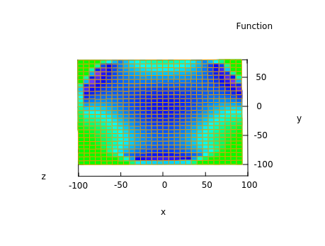
Here is an example of an error similar to what Moriquendi has:
The above error is caused by errors in both diagonal rod length and delta radius. Make sure you have diagonal rod length precisely entered. Calibrate endstops and delta radius (tower positions).
Here is an example of an error similar to what Moriquendi has:
The above error is caused by errors in both diagonal rod length and delta radius. Make sure you have diagonal rod length precisely entered. Calibrate endstops and delta radius (tower positions).
|
Re: Frustrating calibration issue October 21, 2017 05:38AM |
Registered: 9 years ago Posts: 487 |
I've had the printer apart again this morning, I have:
Rechecked joint spacing top and bottom
Remeasured arm length
Measured both diagonals of all three sides, equal to under 0.5mm
Measured carriage joint to z-axis for all carriages, all very close.
The only anomaly I've found is that while my CAD model of the printer suggests a delta radius of ~72mm, autocalibrating the printer always converges on ~85mm, I'm starting to suspect that this may be the problem.
Probing with delta radius set to 72mm makes things slightly better but results is a massive hump in the middle as you's expect.
Unless I'm doing something very wrong with my callipers then the arm length is 215.5mm
Idris
{Precision Piezo} Accurate, repeatable, versatile z-probe plus piezo discs, endstop cables, pt100, 50w heaters.
|
Re: Frustrating calibration issue October 21, 2017 06:34AM |
Registered: 9 years ago Posts: 487 |
So I've been at it again with the callipers just for my own sanity. Arm length is definitely 215.5mm and delta radius is definitely in the region of 85mm, 72mm is far too short.
I feel like I'm missing something important, some assumption that I make or that the firmware makes is incorrect but I can't for the life of me work out what it is.
Idris
{Precision Piezo} Accurate, repeatable, versatile z-probe plus piezo discs, endstop cables, pt100, 50w heaters.
I feel like I'm missing something important, some assumption that I make or that the firmware makes is incorrect but I can't for the life of me work out what it is.
Idris
{Precision Piezo} Accurate, repeatable, versatile z-probe plus piezo discs, endstop cables, pt100, 50w heaters.
|
Re: Frustrating calibration issue October 21, 2017 10:48AM |
Registered: 6 years ago Posts: 20 |
I second moriquendi in everything he says. Besides delta radius which is self determined by the calibration, arm length is measured to 0.1mm of error, all arms have exactly the same length since they fit the same jig, endstop error is under 0.1mm. The printer is square up to 0.1 degree, as much as I trust my digital inclinometer to show.
My error is just like herchek picture, only rotated a few degress clockwise, not just exactly in front of the towers, might be the anticlockwise movement of the head while printing a circle. I've even found an online mathematica script and played with that. Can't find out the cluprit. I've replaced almost everything except the main frame made of 4080 C-beams and and top/bottom 6/8mm cnc alu plates, that is steppers, carriage wheels, hotend, hotendmount, piezo sensor instead of offset BLTouch. I'm thinking of belt slack and a carriage backlash. It drives me crazy.
My error is just like herchek picture, only rotated a few degress clockwise, not just exactly in front of the towers, might be the anticlockwise movement of the head while printing a circle. I've even found an online mathematica script and played with that. Can't find out the cluprit. I've replaced almost everything except the main frame made of 4080 C-beams and and top/bottom 6/8mm cnc alu plates, that is steppers, carriage wheels, hotend, hotendmount, piezo sensor instead of offset BLTouch. I'm thinking of belt slack and a carriage backlash. It drives me crazy.
|
Re: Frustrating calibration issue October 21, 2017 11:57AM |
Registered: 9 years ago Posts: 487 |
I spoke to Arthur Wolf on IRC thinking I was missing something in the config file.
He was of the opinion that very small geometric errors in the build and alignment of the machine, too small to measure by hand, could easily cause errors of the magnitude and type I was seeing.
I had always thought that I could measure and align my printer well enough that I wouldn't need to use grid levelling, so I had it turned off but it seems that I must have got really lucky in the past or by chance had errors that cancelled out. I've now got grid levelling turned on and I'm seeing 0.1mm delta across the bed.
As for what the cause of the error I was seeing earlier is, I have no idea but my printer is working now.
Idris
{Precision Piezo} Accurate, repeatable, versatile z-probe plus piezo discs, endstop cables, pt100, 50w heaters.
|
Re: Frustrating calibration issue October 21, 2017 01:07PM |
Registered: 6 years ago Posts: 20 |
|
Re: Frustrating calibration issue October 21, 2017 04:54PM |
Registered: 9 years ago Posts: 487 |
Are you using smoothie? do you have a grid file on your SD card?
Here's what the relevent parts of my config file look like
Idris
{Precision Piezo} Accurate, repeatable, versatile z-probe plus piezo discs, endstop cables, pt100, 50w heaters.
Here's what the relevent parts of my config file look like
# Levelling strategy

# Example for the delta calibration strategy
leveling-strategy.delta-calibration.enable   true            # Enable basic delta calibration
leveling-strategy.delta-calibration.radius   80             # the probe radius


# Example for the delta grid leveling strategy
leveling-strategy.delta-grid.enable          true            # Enable grid leveling
leveling-strategy.delta-grid.radius          80              # Grid radius in millimeters
leveling-strategy.delta-grid.size            11               # Grid size, must be an odd number
leveling-strategy.delta-grid.do_home         true            # Whether to home before calibration
leveling-strategy.delta-grid.save            true            # Whether to automatically save the grid
leveling-strategy.delta-grid.initial_height  5              # Height at which to start probling
Idris
{Precision Piezo} Accurate, repeatable, versatile z-probe plus piezo discs, endstop cables, pt100, 50w heaters.
|
Re: Frustrating calibration issue October 21, 2017 04:54PM |
Registered: 10 years ago Posts: 732 |
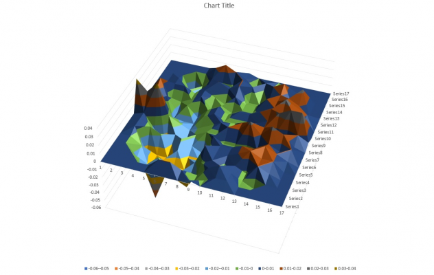
My experience is that printer errors are mostly smaller than geometry errors after calibration. For example, the hight error maps I posted in my previus message simulated geometry errors of 1 mm. Note that this resulted in bed level error less than 0.0.3 mm (because the errors partially compensate each other).
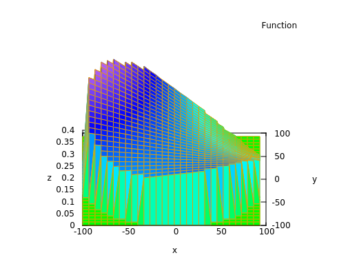
Here is an example of 1 mm error in x coordinate of Z tower:
Notice that 1 mm tower position error resulted in about 0.4 mm bed height error.
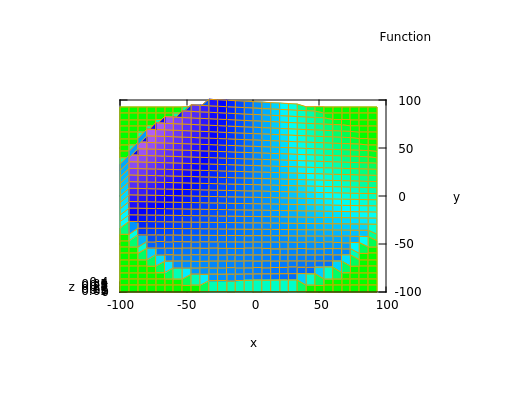
Here is an example of endstop error of 1 mm.
Notice that the resulting bed error is almost planar. That means that endstops can quite well compensate for small bed tilt. The problem is that if you use this feature then your printed parts will be as tilted as the bed is.
executivul: 0.1 mm endstop error is too much. Either adjust the endstop, or (if its error is varying) replace it.
|
Re: Frustrating calibration issue October 21, 2017 04:57PM |
Registered: 10 years ago Posts: 14,672 |
Moriquendi, the type of pattern you are now getting is symptomatic of either the diagonal rod length or the tower steps/mm being set incorrectly in the firmware,
Can you confirm that the 215.5mm arm length you have measured is between the centres of rotation of the bearings?
Also check that your firmware steps/mm setting matches what you are actually getting from the mechanics. I have heard that unless the belt is under a lot of tension, the pitch of a GT2 belt is in practice slightly less than 2mm.
Edited 1 time(s). Last edit at 10/21/2017 04:59PM by dc42.
Large delta printer [miscsolutions.wordpress.com], E3D tool changer, Robotdigg SCARA printer, Crane Quad and Ormerod
Disclosure: I design Duet electronics and work on RepRapFirmware, [duet3d.com].
|
Re: Frustrating calibration issue October 21, 2017 05:36PM |
Registered: 9 years ago Posts: 487 |
Quote
dc42
Can you confirm that the 215.5mm arm length you have measured is between the centres of rotation of the bearings?
Also check that your firmware steps/mm setting matches what you are actually getting from the mechanics. I have heard that unless the belt is under a lot of tension, the pitch of a GT2 belt is in practice slightly less than 2mm.
Arm length is measured from ball centre to ball centre.
I'll put some effort into measuring steps/MM tomorrow morning and see what I come up with.
Hercek, how are you modelling those height maps? it seems to me that a pictorial guide to the effects of geometry errors might be a very useful diagnostic tool.
Idris
{Precision Piezo} Accurate, repeatable, versatile z-probe plus piezo discs, endstop cables, pt100, 50w heaters.
|
Re: Frustrating calibration issue October 21, 2017 05:40PM |
Registered: 10 years ago Posts: 732 |
Sorry I do not have a newbie friendly tool for that.
I'm doing it using this: [github.com]
One must understand the math in the notebook a bit to know how to simulate different error kinds.
I'm doing it using this: [github.com]
One must understand the math in the notebook a bit to know how to simulate different error kinds.
|
Re: Frustrating calibration issue October 22, 2017 04:49AM |
Registered: 9 years ago Posts: 487 |
Thats a shame, I'm not sure my maths is up to that, great tool though.
I've measured the physical steps/mm and the error is 0.1% so I don't think that's contributing significantly.
Idris
{Precision Piezo} Accurate, repeatable, versatile z-probe plus piezo discs, endstop cables, pt100, 50w heaters.
I've measured the physical steps/mm and the error is 0.1% so I don't think that's contributing significantly.
Idris
{Precision Piezo} Accurate, repeatable, versatile z-probe plus piezo discs, endstop cables, pt100, 50w heaters.
|
Re: Frustrating calibration issue October 22, 2017 03:28PM |
Registered: 6 years ago Posts: 20 |
I don't want to hijack the topic, but I'll keep posting here maybe moriquendi has the same problem 
1. I've rechecked the machine is square and mechanically adjusted the endstops untill I get:
2. Ran the LSQ smoothie branch to calibrate and G29 P1 I17 to map the height, I get 0.16mm of difference:
3. Probed and activated grid compensation and reprobed with G29, I get 0.0877mm of difference:
Calibration grid had 15 points, probing 17, so points don't overlap and I get real values.
4. Tried printing a circle aaaannnndddddd:

1. I've rechecked the machine is square and mechanically adjusted the endstops untill I get:
Recv: Calibrating Endstops: target 0.030000mm, radius 155.000000mm
Recv: set trim to X:0.000000 Y:0.000000 Z:0.000000
Recv: initial Bed ht is 480.934326 mm
Recv: center probe: -0.0022
Recv: T1-0 Z:4.8831
Recv: T2-0 Z:4.9082
Recv: T3-0 Z:4.9019
Recv: trim already set within required parameters: delta 0.025085
Recv: Calibrating delta radius: target 0.030000, radius 155.000000
2. Ran the LSQ smoothie branch to calibrate and G29 P1 I17 to map the height, I get 0.16mm of difference:
3. Probed and activated grid compensation and reprobed with G29, I get 0.0877mm of difference:
Calibration grid had 15 points, probing 17, so points don't overlap and I get real values.
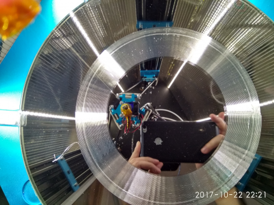
4. Tried printing a circle aaaannnndddddd:
|
Re: Frustrating calibration issue October 26, 2017 07:22PM |
Registered: 9 years ago Posts: 76 |
|
Re: Frustrating calibration issue October 26, 2017 07:29PM |
Registered: 10 years ago Posts: 14,672 |
Quote
mikes3ds
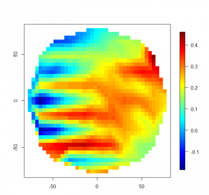
What you guys using to plot your height maps. I am thinking about using R, but it seems there are some ones out there already?>
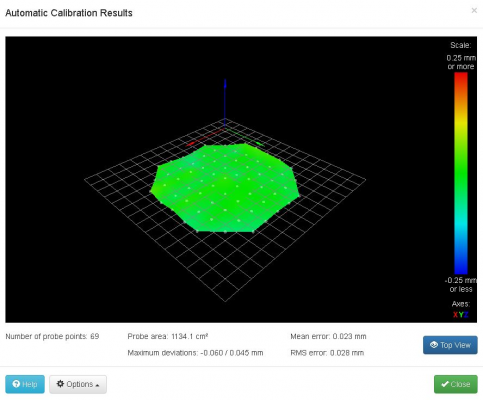
On the Duet the height map plot is built into the standard web interface. Example:
You can rotate and zoom it, and hover over the dots to see the height error at each probe point.
The rendering is done in the browser using JavaScript, which takes data read from the height map file which is in CSV format. The credit for implementing this belongs to Christian Hammacher, not me.
Edited 2 time(s). Last edit at 10/26/2017 07:34PM by dc42.
Large delta printer [miscsolutions.wordpress.com], E3D tool changer, Robotdigg SCARA printer, Crane Quad and Ormerod
Disclosure: I design Duet electronics and work on RepRapFirmware, [duet3d.com].
|
Re: Frustrating calibration issue October 26, 2017 07:40PM |
Registered: 9 years ago Posts: 76 |
|
Re: Frustrating calibration issue October 26, 2017 10:12PM |
Registered: 9 years ago Posts: 76 |
|
Re: Frustrating calibration issue October 27, 2017 03:39AM |
Registered: 6 years ago Posts: 20 |
Sorry, only registered users may post in this forum.
