DemonDeltaTube - A delta inside an acrylic tube... Build
Posted by DjDemonD
|
DemonDeltaTube - A delta inside an acrylic tube... Build December 29, 2017 05:22PM |
Registered: 8 years ago Posts: 3,525 |
So this was not my idea but I did like it the original idea was presented here [forums.reprap.org]
The idea is to build a delta printer inside a PVC or acrylic tube, the tube will act as both the frame and an enclosure. The first issue is not how to mount things to the inside of a tube, this is an issue, but it is getting hold of a suitable tube. My options were PVC sewer pipe or some sort of display case-type acrylic tubing. PVC sewer pipe is available in 8-foot lengths in 300mm diameter or thereabouts, and its expensive. Offcuts would be great but I have no source for them, I've tried local scrap stores, junk shops etc.. Building sites might also be worth a look but nothing came up. So I looked into ready-made acrylic tubing but a 300mm diameter x 600mm high tube in 4mm acrylic costs around £160.
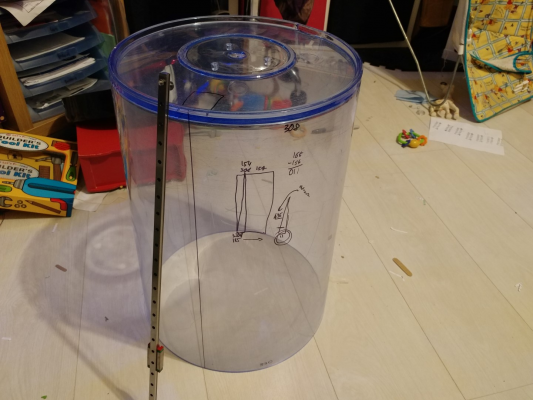
So how about a fishtank? I came across this one called a Biube eBay provided me with one second hand (no fish included) for £30. Its a 300mm diameter, transparent tube. It is certainly preferable to do this with a transparent tube, delta printers look amazing in function and not being able to see inside would be quite unfortunate.
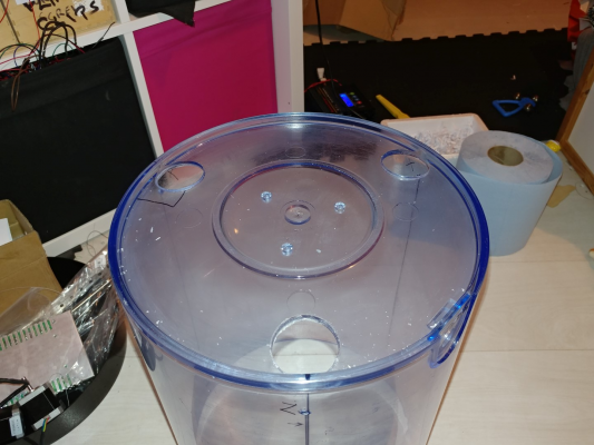
So fishtank arrived, acrylic could use a polish but its quite serviceable. 4mm thick walls.
First snag the diameter at the top and the diameter at the bottom are not the same, it is essentially a plastic cup, not a cylinder.
The difference in radius is 11mm over 435mm.
My plan is to use linear rails, I have used rollers on extrusions once before on a kossel mini, it worked pretty well, but my other two deltas use rails, and they work better. I have got 3x "chi-win" MGN9H rails from ebay for around £15 each.
How to drill the holes? Since precision is required and with a smooth "cylinder" (I will refer to the fishtank as a cylinder from here on in as "frustum of a cone" is not particularly eloquent) there is nothing to align the rails on, unlike a hexagonal or triangular framed conventional delta design - there appear to be 4 methods that I can determine.
1) use paper circles possibly with appropriate markings printed onto them at 0, 120 and 240 degrees, to make marks on the cylinder at the top and the bottom, and draw a line with a straight edge. - Would work but seems a little imprecise.
2) make a large paper template that I can wrap around the cylinder with the hole markings printed onto it after drawing it in a 2D design package. - needs a large paper printer to work, my cylinder is not actually cylindrical, and I have no expertise with 2D drawing packages.
3) Get someone to mount the cylinder in a 5 axis cnc and precision cut the holes. Probably the best idea, but I don't know anyone offhand, or how easy this would be to do.
4) Make a template using my existing Kossel XL printer to place inside the cylinder to mark the axis along which to drill the holes.
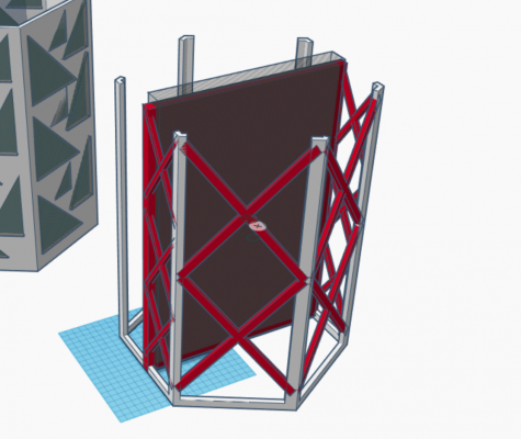
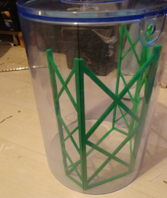
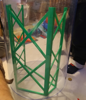
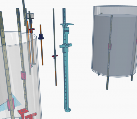
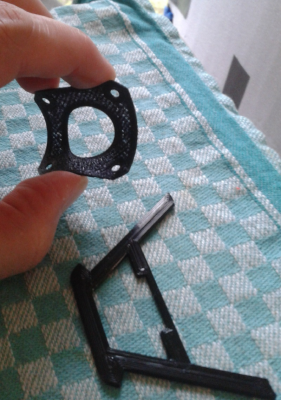
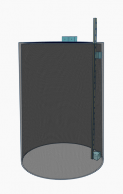
So given that 4 is more fun, I designed a scaffold in Tinkercad, after modelling the cylinder and determining where 0, 120 and 240 degrees were. The idea being I would insert this into the cylinder and use the vertices to mark the axis where the rails would be mounted.
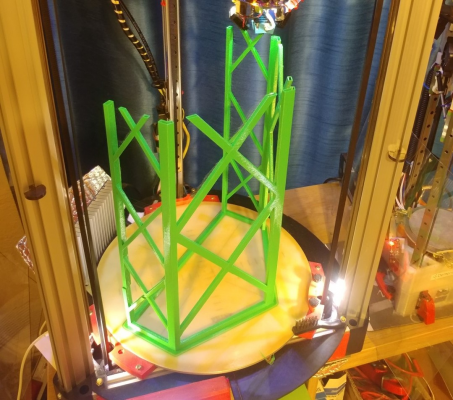
Now to print it. This would be by far the largest object I have printed, at 300mm width and 386mm tall. PLA was chosen, I don't need any warping.
Several attempts were made, I needed to remove bed clamps, move fans, and generally squeeze every last mm of xy space out of my kossel XL. There was one slight layer shift on one "leg" from curling overhangs, and it stopped with a heater fault with around 50mm to go. My heater wires has come loose. Luckily I'm using RRF on duetwifi and the power_resume feature came to my recuse. Only the hotend heater was disabled, I rebooted the printer, making sure to immediately return the bed set temp to 75 so as not to lose adhesion on the part, then fixed the heater wiring, and sent M916, whereby it resumed printing where it left off. After a total of 17 hours it finished.
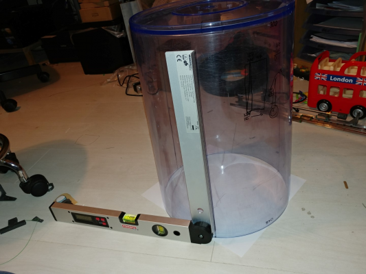
Now to mark the lines where the rails should be:
These lines are vertical measured using a square and a digital angle finder.
I will need to offset the rails at the bottom by whatever distance is required by simple Pythagorean geometry to ensure they are vertical in and X and Y.
Now since this machine is going to be quite experimental I am going to try to use leadscrews. I looked into ballscrews versus leadscrews, and whilst ballscrews are more efficient, they don't offer any passive holding when motors are powered-off so I don't want my effector dropping to the bed after a print finishes. Leadscrews at 8mm lead should be 400 steps/mm for 1.8 deg motors. This should offer sufficient resolution 0.0025mm, and speed (using 24v low inductance motors). I designed an axis which might allow me to attach the motors and leadscrews to the rails. I intend to print all parts in something like Ngen from Colorfabb.
Controller will be duetwifi and intend to use sensor less homing for endstops, and a Precision Piezo sensor in the hotend, which will be a raised hotend design. I have an e3d gold v6 hotend on order.
One thing that will also make this printer unusual is that it will essentially have an open base. So it could be placed onto a variety of surfaces to print on, using the fast delta calibration on RRF. The intention currently is to get a tooling plate bed with silicone heater as the default printing surface, and that the printer would be lifted off the bed to free the parts when finished. This will probably prove impractical so a door might have to be made in the cylinder.
Edited 3 time(s). Last edit at 12/29/2017 06:47PM by DjDemonD.
Simon Khoury
Co-founder of [www.precisionpiezo.co.uk] Accurate, repeatable, versatile Z-Probes
Published:Inventions
|
Re: DemonDeltaTube - A delta inside an acrylic tube... Build December 29, 2017 05:41PM |
Registered: 8 years ago Posts: 3,525 |
Based on the axis design above, what sort of motor coupler to the leadscrews would people recommend? Rigid? Flexible?
Simon Khoury
Co-founder of [www.precisionpiezo.co.uk] Accurate, repeatable, versatile Z-Probes
Published:Inventions
Simon Khoury
Co-founder of [www.precisionpiezo.co.uk] Accurate, repeatable, versatile Z-Probes
Published:Inventions
|
Re: DemonDeltaTube - A delta inside an acrylic tube... Build December 29, 2017 09:59PM |
Registered: 9 years ago Posts: 483 |
|
Re: DemonDeltaTube - A delta inside an acrylic tube... Build December 30, 2017 03:12AM |
Registered: 8 years ago Posts: 3,525 |
Are you sure? Whilst a tilt on the bed relative to the towers is able to compensate for, even RRF which probably has the most sophisticated delta calibration going, cannot compensate for leaning towers. Radius error, and I think possibly position error, can be compensated, but there is a presumption that the towers are all parallel with one another and basically as close to 90 degrees to the bed as possible.
Simon Khoury
Co-founder of [www.precisionpiezo.co.uk] Accurate, repeatable, versatile Z-Probes
Published:Inventions
Simon Khoury
Co-founder of [www.precisionpiezo.co.uk] Accurate, repeatable, versatile Z-Probes
Published:Inventions
|
Re: DemonDeltaTube - A delta inside an acrylic tube... Build December 30, 2017 03:54AM |
Registered: 10 years ago Posts: 14,672 |
Quote
etfrench
I don't think you need to have the linear rails at 90 degrees to the bed. Delta software should be able to handle the offset.
Standard delta geometry used Pythagorus to work out the tower heights:
x^2 + y^2 + h^2 = L^2 which gives h = sqrt(L^2 - x^2 - y^2)
where x, y are the head X and Y offsets from the virtual tower position and L is the diagonal rod length.The most complicated operation is a square root.
If the towers are not parallel then it gets more complicated. We could use the cosine rule to work out the tower height:
r = sqrt(x^2 + y^2)
r^2 + h^2 -2*r*h*cos(theta) = L^2
If we know theta then this is still quadratic in h, although we now have to calculate a second square root to determine r. Unfortunately, theta is the angle between the tower and the direction from the tower base to the head, which varies with x and y. I haven't worked it out, but it may require trigonometry to calculate theta.
So although it's not impossible to do the computations when the towers are leaning, it looks a lot more complicated, and likely not possible to implement segmentation-free delta movement.
DjDemonD will need to print or machine spacers to mount the linear rails on the inside of the tube anyway. It shouldn't be difficult to taper them and use different thicknesses at different heights.
Large delta printer [miscsolutions.wordpress.com], E3D tool changer, Robotdigg SCARA printer, Crane Quad and Ormerod
Disclosure: I design Duet electronics and work on RepRapFirmware, [duet3d.com].
|
Re: DemonDeltaTube - A delta inside an acrylic tube... Build December 30, 2017 04:13AM |
Registered: 8 years ago Posts: 5,232 |
I had good results with flexible couplers between leadscrew and stepper shaft. But I added a steel ball ( 4.5mm ) between them. Now the DOF in Z-direction is eliminated and it can only flex in X&Y.
Was it really necessary to print this tall scaffold? ( c'mon you were just showing off ) One template for the bottom and top, properly aligned would've worked too...
Edited 1 time(s). Last edit at 12/30/2017 04:17AM by o_lampe.
Was it really necessary to print this tall scaffold? ( c'mon you were just showing off
 ) One template for the bottom and top, properly aligned would've worked too...
Edited 1 time(s). Last edit at 12/30/2017 04:17AM by o_lampe.
|
Re: DemonDeltaTube - A delta inside an acrylic tube... Build December 30, 2017 04:14AM |
Registered: 8 years ago Posts: 3,525 |
@dc42 That's certainly my intention, however, if you want to use this as a testbed for leaning towers that would be an interesting experiment and would add something more to this intentionally quite radical design.
@O_lampe I'll try flex initially.the steel ball sounds like a good idea. I've only seen one leadscrew delta which got terrible layer registration but then it was a one-smooth-rod design so nowhere near enough constraint for the carriages. I'm hoping rails will prevent this problem. I am toying with the idea of a connection between leadscrew nuts and carriages which is unconstrained in XY to allow for any wobble in the screws. Might also need antibacklash nuts so the axis design is going to change a lot I think.
No, the scaffold wasn't necessary but I have always wanted to find an excuse to actually print something big on the Xl given that as with most large 3d printers this 300x300x400 print volume often only prints 20x30x40 parts. My son now has it as a launch tower for Thunderbird 3.
Edited 4 time(s). Last edit at 12/30/2017 04:48AM by DjDemonD.
Simon Khoury
Co-founder of [www.precisionpiezo.co.uk] Accurate, repeatable, versatile Z-Probes
Published:Inventions
|
Re: DemonDeltaTube - A delta inside an acrylic tube... Build January 01, 2018 10:38AM |
Registered: 8 years ago Posts: 3,525 |
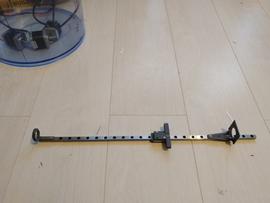
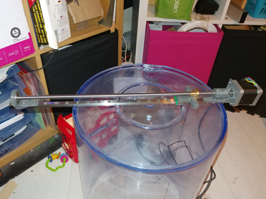
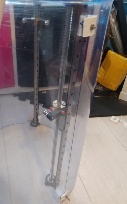
A trial assembly of an axis. I've already changed the motor bracket to be much thicker with thicker supporting brackets beneath. I don't know if this will prove stiff enough, I suspect I will beef-up all of it except the carriage which seems fine. Waiting on leadscrews to arrive before work can continue. I will have to cut the rails to go with this design, as the motor body overlaps the rail at present. So I want to be fairly sure the axis will work before doing so.
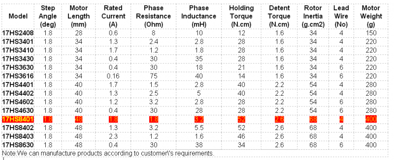
Also some motors from my old deceased I3 clone located with the following specifications:
Simon Khoury
Co-founder of [www.precisionpiezo.co.uk] Accurate, repeatable, versatile Z-Probes
Published:Inventions
Also some motors from my old deceased I3 clone located with the following specifications:
Simon Khoury
Co-founder of [www.precisionpiezo.co.uk] Accurate, repeatable, versatile Z-Probes
Published:Inventions
|
Re: DemonDeltaTube - A delta inside an acrylic tube... Build January 02, 2018 03:25AM |
Registered: 8 years ago Posts: 5,232 |
The noise and vibrations of the steppers will be amplified by the tube. Duets 16/256 microstepping will reduce that to a minimum, but I'd still think of decoupling the tube from the rails. Could be a simple gasket printed from TPU. I have done that on several occasions between stepper and bracket or Delta bottom corner and MDF plate.
Decoupling the leadscrew from the carrier is another good idea. I have a vision of it, I can't explain. Maybe I add a napkin sketch later...
Problem is, you have to block the ballscrew nut from rotating as well.
Decoupling the leadscrew from the carrier is another good idea. I have a vision of it, I can't explain. Maybe I add a napkin sketch later...
Problem is, you have to block the ballscrew nut from rotating as well.
|
Re: DemonDeltaTube - A delta inside an acrylic tube... Build January 02, 2018 04:57AM |
Registered: 8 years ago Posts: 3,525 |
I certainly expect it to be a noisy machine even with interpolated 1/256 microstepping. My kossel XL is now enclosed with a broadly cylindrical enclosure and its 2-3 times noisier as a result. It's still quieter than it would be if it were open-frame, and did not have the TMC stepper driver goodness though.
I will make some dampening parts (an excuse to use the flexible filament I bought) and try with/without them.
Simon Khoury
Co-founder of [www.precisionpiezo.co.uk] Accurate, repeatable, versatile Z-Probes
Published:Inventions
I will make some dampening parts (an excuse to use the flexible filament I bought) and try with/without them.
Simon Khoury
Co-founder of [www.precisionpiezo.co.uk] Accurate, repeatable, versatile Z-Probes
Published:Inventions
|
Re: DemonDeltaTube - A delta inside an acrylic tube... Build January 03, 2018 04:25PM |
Registered: 8 years ago Posts: 3,525 |
Okay so how should I put this... DO NOT use the printed template.
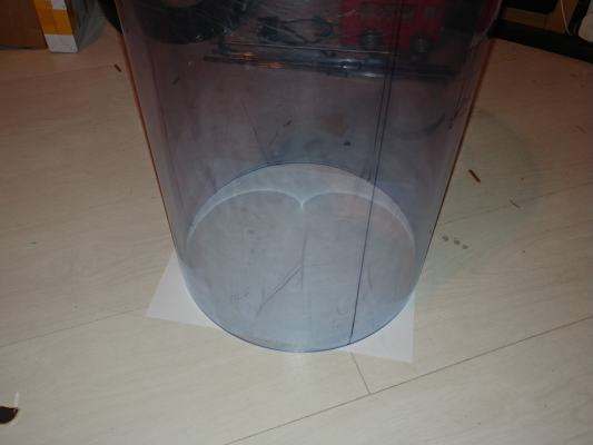
Whilst it makes a great launch tower for my kids toy rocket, I was slightly dubious about the angular positions I'd marked for the 3 axes. So I made a circular object, added dots at 0,120 and 240 degrees around the perimeter, exported it to an svg, and then printed it on paper.
One of the towers was about 5 degrees out of position. I appreciate RRF software can compensate but I might be asking a lot.
Now redrawn in the correct positions.
If you could print a full sized template, it would work, but I could only print a half sized one and this was not accurate enough.
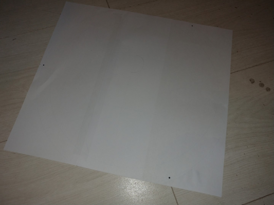
Paper template as PNG.
There is something there but its 325mm across so needs to be viewed fullscreen. The box in the centre is 100x100 for calibration checking of paper printer.
Edited 2 time(s). Last edit at 01/04/2018 08:26AM by DjDemonD.
Simon Khoury
Co-founder of [www.precisionpiezo.co.uk] Accurate, repeatable, versatile Z-Probes
Published:Inventions
|
Re: DemonDeltaTube - A delta inside an acrylic tube... Build January 04, 2018 03:55AM |
Registered: 8 years ago Posts: 5,232 |
|
Re: DemonDeltaTube - A delta inside an acrylic tube... Build January 04, 2018 04:01AM |
Registered: 8 years ago Posts: 3,525 |
Well, they're cheap and readily available, Lidl and Aldi are my favourite tool suppliers. Though I think I'll measure 3 times and drill once.
Another used fishtank would probably be not too hard to get hold of, but I'd be upset if I'd paid £150 for a new acrylic cylinder - although at least it would be cylindrical!
Simon Khoury
Co-founder of [www.precisionpiezo.co.uk] Accurate, repeatable, versatile Z-Probes
Published:Inventions
Another used fishtank would probably be not too hard to get hold of, but I'd be upset if I'd paid £150 for a new acrylic cylinder - although at least it would be cylindrical!
Simon Khoury
Co-founder of [www.precisionpiezo.co.uk] Accurate, repeatable, versatile Z-Probes
Published:Inventions
|
Re: DemonDeltaTube - A delta inside an acrylic tube... Build January 04, 2018 11:53AM |
Registered: 8 years ago Posts: 601 |
|
Re: DemonDeltaTube - A delta inside an acrylic tube... Build January 04, 2018 12:13PM |
Registered: 8 years ago Posts: 3,525 |
Like Renishaw touch probe? I wouldn't know where to start.
Simon Khoury
Co-founder of [www.precisionpiezo.co.uk] Accurate, repeatable, versatile Z-Probes
Published:Inventions
Simon Khoury
Co-founder of [www.precisionpiezo.co.uk] Accurate, repeatable, versatile Z-Probes
Published:Inventions
|
Re: DemonDeltaTube - A delta inside an acrylic tube... Build January 04, 2018 12:55PM |
Registered: 8 years ago Posts: 601 |
The other option perhaps is to mount the tube in a vice with a column in the middle, a probe attached to each guide is then used to test if it is straight against the central column. This will at least let you know if each guide is straight relative to each other
non straight guides will need jigging around and shims used etc. Drilling mounting holes accurately is not necessarily needed, as long as they are tightened accurately. A flat surface on the inside of the tube will be very useful.
non straight guides will need jigging around and shims used etc. Drilling mounting holes accurately is not necessarily needed, as long as they are tightened accurately. A flat surface on the inside of the tube will be very useful.
|
Re: DemonDeltaTube - A delta inside an acrylic tube... Build January 04, 2018 01:57PM |
Registered: 8 years ago Posts: 487 |
I've run into the problem of trying to print large plans with an A4 printer before, try BigPrint
Idris
{Precision Piezo} Accurate, repeatable, versatile z-probe plus piezo discs, endstop cables, pt100, 50w heaters.
Idris
{Precision Piezo} Accurate, repeatable, versatile z-probe plus piezo discs, endstop cables, pt100, 50w heaters.
|
Re: DemonDeltaTube - A delta inside an acrylic tube... Build January 04, 2018 04:50PM |
Registered: 10 years ago Posts: 14,672 |
Quote
DjDemonD
One of the towers was about 5 degrees out of position. I appreciate RRF software can compensate but I might be asking a lot.
Someone built a "square delta" with 3 towers at 90 degree intervals, and used RRF to control it.
Large delta printer [miscsolutions.wordpress.com], E3D tool changer, Robotdigg SCARA printer, Crane Quad and Ormerod
Disclosure: I design Duet electronics and work on RepRapFirmware, [duet3d.com].
|
Re: DemonDeltaTube - A delta inside an acrylic tube... Build January 04, 2018 04:59PM |
Registered: 8 years ago Posts: 3,525 |
Sounds cool, but I am going to try to adapt a fairly precisely built delta into this fishtank. I suspect I will not get that close, and will be heavily relying on compensation to make it work, which is fine - let the firmware take the strain.
I do now have my rails cut and an axis built. I am going to add guides to the printed parts so that they sit more squarely on the rails, and my printed motor coupling is next to useless (metal ones on order).
Question for the leadscrew experts, I might use a rigid coupler as everything aligns quite well. Should I be using another bearing at the top end of the axis, or will the motor and a rigid coupler be sufficient?
Simon Khoury
Co-founder of [www.precisionpiezo.co.uk] Accurate, repeatable, versatile Z-Probes
Published:Inventions
|
Re: DemonDeltaTube - A delta inside an acrylic tube... Build January 05, 2018 10:13AM |
Registered: 10 years ago Posts: 14,672 |
I assumed you were going to put the motors at the top, to keep them out of the way of the print.
Large delta printer [miscsolutions.wordpress.com], E3D tool changer, Robotdigg SCARA printer, Crane Quad and Ormerod
Disclosure: I design Duet electronics and work on RepRapFirmware, [duet3d.com].
Large delta printer [miscsolutions.wordpress.com], E3D tool changer, Robotdigg SCARA printer, Crane Quad and Ormerod
Disclosure: I design Duet electronics and work on RepRapFirmware, [duet3d.com].
|
Re: DemonDeltaTube - A delta inside an acrylic tube... Build January 05, 2018 12:10PM |
Registered: 8 years ago Posts: 3,525 |
I am. I'm going to cut holes in the "top" which is the bottom of the fishtank.
Simon Khoury
Co-founder of [www.precisionpiezo.co.uk] Accurate, repeatable, versatile Z-Probes
Published:Inventions
Simon Khoury
Co-founder of [www.precisionpiezo.co.uk] Accurate, repeatable, versatile Z-Probes
Published:Inventions
|
Re: DemonDeltaTube - A delta inside an acrylic tube... Build January 06, 2018 12:03PM |
Registered: 8 years ago Posts: 3,525 |
Progress so far...
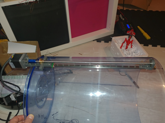
Determined the vertical position of the axes by using the trial assembly of an axis and placing it against the side of the cylinder. I wound the carriage (which could be altered if needed later) to the top and bottom of its travel to imagine the possible arm angles I could achieve. Thinkyhead's delta calculator is useful to help visualise it. [www.thinkyhead.com]
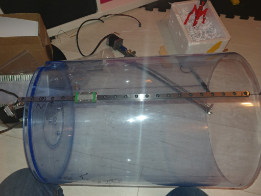
Decided to align one of the holes in the rails with the top edge of the cylinder for easy marking of the hole positions.
The axis now sports a nice anodised rigid coupler which allows smooth travel no binding.
Using one of the other unassembled rails as a hole guide I marked the positions for the holes.
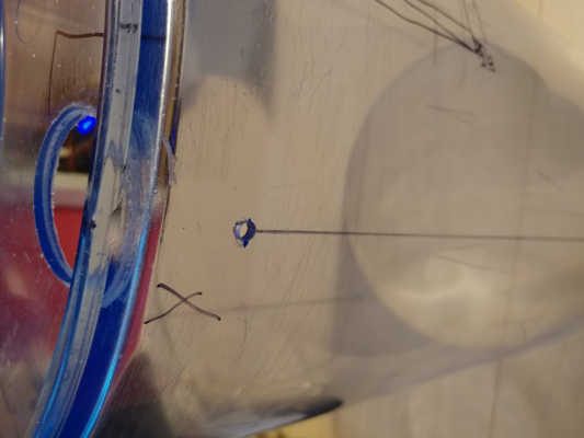
Then I drilled the holes using a 5mm spur point bit, use high rpm but very light pressure. 5mm allows some wiggle when fitting the axes to correct fine errors in verticality.
Then I determined by measuring the part of the axis which will sit level with the top of the printer (bottom of the fishtank) the size for the holes in the top that the motors will project out of. 35mm was enough but I only have a 40mm hole saw.
Again use high rpm with a pecking motion and loads of spray lubricant like wd40, this cools the drill bit. You can see the holes got better so if you've got some spare acrylic do a few test holes first.
So now I need to know what size the standoffs need to be to mount the rails to the inside of this not cylindrical fishtank.
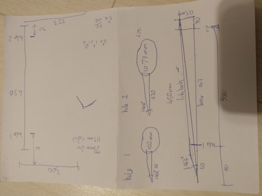
So the difference in radius between top and bottom is 11.5mm so a bit of trigonometry determines that the top hole sits 1.02mm out from a hypothetical vertical line (the rail essentially) and the bottom hole sits 10.73mm out from the vertical line. There is some clearance required by the rail at the top where it sticks out so my standoffs are going to be 9.02mm top and 18.73mm bottom. I will make them wide based, to reduce the stress around the holes (this is acrylic after all).
I think I will model the conical fishtank more accurately in CAD and the rail and design the parts between them, but verify the standoff distance matches the one calculated.
Edited 4 time(s). Last edit at 01/06/2018 12:41PM by DjDemonD.
Simon Khoury
Co-founder of [www.precisionpiezo.co.uk] Accurate, repeatable, versatile Z-Probes
Published:Inventions
|
Re: DemonDeltaTube - A delta inside an acrylic tube... Build January 09, 2018 02:33AM |
Registered: 7 years ago Posts: 154 |
|
Re: DemonDeltaTube - A delta inside an acrylic tube... Build January 27, 2018 06:00PM |
Registered: 8 years ago Posts: 3,525 |
Okay so this project has been a bit slow but I did manage to get some done.
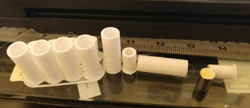
Since I have a set of Haydns Delrin magball arms on my Xl and they work really well, why not make some myself. I used Haydns files from youmagine [www.youmagine.com]
Printed the required 12 sets in white PLA (for stiffness). Bought 12x n52 neodymium magnets cylindrical in 10mm width x 15mm height (eBay).
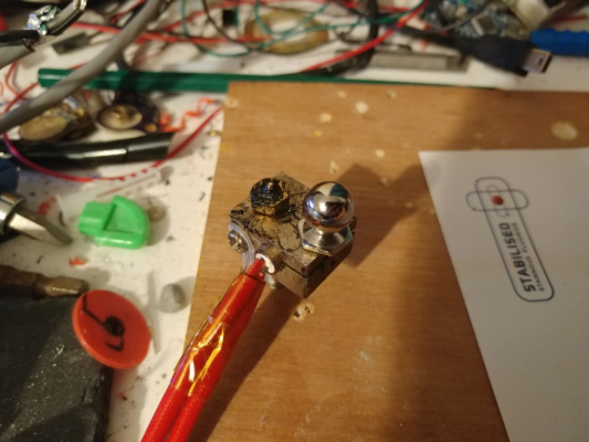
Then used Olampe's excellent suggestion of screwing a ball stud into the heater cartridge clamp of a spare heater block. Used 150 deg C and a smear of light oil to smooth and shape the sockets of the rod ends. Didn't worry too much about trying to get the gap between the magnet and ball stud exact as I haven't assembled the rods and any variance will be adjusted for at assembly. But it works very nicely. Don't forget later when you think you've lost one of the ball studs, its attached to the heater block sitting on the bench.
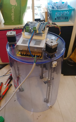
Now I had trial fitted an axis to the cylinder after creating standoffs of the correct thickness and contour in Tinkercad (I basically modelled the "cylinder" correctly with its narrower top and wider base, added a model of an mgn9 rail standing vertically and then created the standoffs by making the cylinder a hole and cutting them out. I also recessed the rail into the standoffs to make for greater stability once mounted as the trial fitted one's were too wobbly.
I also made a mount for my PSU on top (standard 400w Chinese brick led psu) and a bracket for duetwifi card. This has some extra holes punched in it which allow the fan from the PSU to cool (or warm up - I have yet to test) the duetwifi card.
I copied and modified my config from my Xl stripping a lot out, setup sensorless homing as per duet wiki and it works threshold is S1 for sensorless homing, on my setup.
Edited 1 time(s). Last edit at 01/28/2018 06:18PM by DjDemonD.
Simon Khoury
Co-founder of [www.precisionpiezo.co.uk] Accurate, repeatable, versatile Z-Probes
Published:Inventions
|
Re: DemonDeltaTube - A delta inside an acrylic tube... Build January 28, 2018 03:05AM |
Registered: 8 years ago Posts: 5,232 |
Thanks for trying out my method 
I hope PLA will survive the mild acid WD40 contains...a drop of machine oil would've been safer?!
Do you have a clever jig to assemble the rods? I thought of using an aluminum extrusion as base for a fixed ballstud and a ballstud moving axially.
( My stuff from Haydn is still held in customs )
)
Edited 1 time(s). Last edit at 01/28/2018 03:10AM by o_lampe.

I hope PLA will survive the mild acid WD40 contains...a drop of machine oil would've been safer?!
Do you have a clever jig to assemble the rods? I thought of using an aluminum extrusion as base for a fixed ballstud and a ballstud moving axially.
( My stuff from Haydn is still held in customs
 )
)Edited 1 time(s). Last edit at 01/28/2018 03:10AM by o_lampe.
|
Re: DemonDeltaTube - A delta inside an acrylic tube... Build January 28, 2018 05:05AM |
Registered: 8 years ago Posts: 3,525 |
I'm printing something now it's a pla base with a removable peg at one end with space for ballstuds. I don't know if it will be stiff enough to be repeatable but I'll give it a try.
haydnrodjig200mm.stl
Edited 1 time(s). Last edit at 01/28/2018 05:08AM by DjDemonD.
Simon Khoury
Co-founder of [www.precisionpiezo.co.uk] Accurate, repeatable, versatile Z-Probes
Published:Inventions
haydnrodjig200mm.stl
Edited 1 time(s). Last edit at 01/28/2018 05:08AM by DjDemonD.
Simon Khoury
Co-founder of [www.precisionpiezo.co.uk] Accurate, repeatable, versatile Z-Probes
Published:Inventions
|
Re: DemonDeltaTube - A delta inside an acrylic tube... Build January 28, 2018 11:03AM |
Registered: 8 years ago Posts: 3,525 |
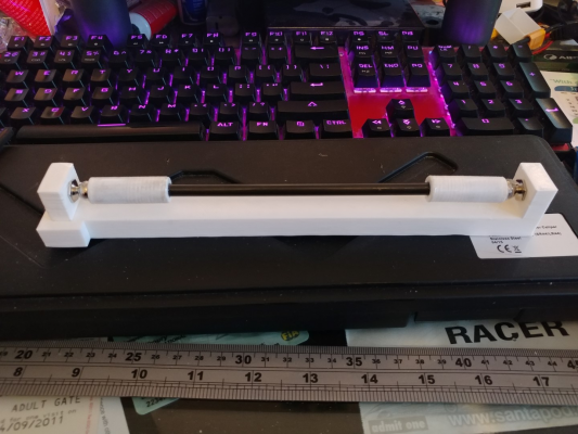
So seems pretty good, make sure the pullout part pulls out and relocates with just a little resistance. I just refined the holes with an 8mm bit. The ball studs screw into the plastic (2.8mm holes). After that I put vaseline on the balls, then added a little 5 min (30 minutes realistically) epoxy resin on top of the magnet which is already in the rod end. Then the inner printed part, then the rod, some epoxy will be forced out of both ends (hence the vaseline on the balls). You need to push the inner parts back into place after fitting it to the jig and wipe any excess epoxy away.
I put the jig on thingiverse. [www.thingiverse.com]
Edited 2 time(s). Last edit at 01/28/2018 06:14PM by DjDemonD.
Simon Khoury
Co-founder of [www.precisionpiezo.co.uk] Accurate, repeatable, versatile Z-Probes
Published:Inventions
I put the jig on thingiverse. [www.thingiverse.com]
Edited 2 time(s). Last edit at 01/28/2018 06:14PM by DjDemonD.
Simon Khoury
Co-founder of [www.precisionpiezo.co.uk] Accurate, repeatable, versatile Z-Probes
Published:Inventions
|
Re: DemonDeltaTube - A delta inside an acrylic tube... Build January 29, 2018 03:07AM |
Registered: 8 years ago Posts: 5,232 |
|
Re: DemonDeltaTube - A delta inside an acrylic tube... Build January 29, 2018 05:56AM |
Registered: 8 years ago Posts: 3,525 |
Well sure that's another way to do it, my XL can print this in PLA without any difficulty, you could make a joint in the middle and print it in two pieces, or just use the ends and screw them to a plank of wood.
But I've got 6 rods made up on this jig which all look to be the same length (I have some ball bearings which match the ball studs so I will put them on the ends and measure them with calipers tonight).
Interested to see your version and to see how reliably it produces equal length rods.
Edited 1 time(s). Last edit at 01/29/2018 10:46AM by DjDemonD.
Simon Khoury
Co-founder of [www.precisionpiezo.co.uk] Accurate, repeatable, versatile Z-Probes
Published:Inventions
|
Re: DemonDeltaTube - A delta inside an acrylic tube... Build January 29, 2018 01:06PM |
Registered: 8 years ago Posts: 3,525 |
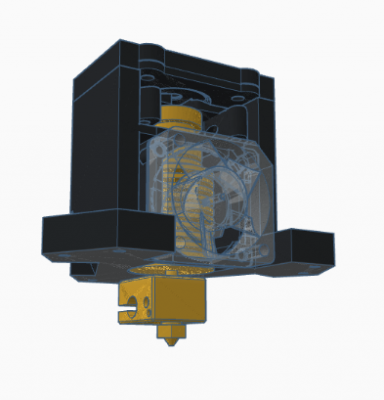
New raised effector design with integrated Precision Piezo sensor.
Not sure if the structure on top will interfere with the rods yet.
There are two cut-outs on the sides for bonding in 30mm sunon blower fans.
Edited 1 time(s). Last edit at 01/29/2018 01:53PM by DjDemonD.
Simon Khoury
Co-founder of [www.precisionpiezo.co.uk] Accurate, repeatable, versatile Z-Probes
Published:Inventions
Sorry, only registered users may post in this forum.
