Haydns printed Mag Rods improved
Posted by o_lampe
|
Re: Haydns printed Mag Rods improved February 28, 2018 08:34AM |
Registered: 6 years ago Posts: 1,007 |
Quote
Haydn
Hi MKSA,
I contracted with a machine shop in China to have these ball studs custom made.
They work great in delta printers, because they're inherently zero-backlash.
....
Thanks but I wanted to know if they are CNC made from bar stock, or an assembly of a ball (from a bearing) and the screw part, what about the sphere tolerance, roundness and if they were hardened.
Edited 1 time(s). Last edit at 02/28/2018 08:41AM by MKSA.
"A comical prototype doesn't mean a dumb idea is possible" (Thunderf00t)
|
Re: Haydns printed Mag Rods improved March 14, 2018 06:43AM |
Registered: 8 years ago Posts: 5,232 |
I just noticed, the Delrin sleeves need a bit of inrun time. They collect some black dust between ball and magnet.
I tried to roll the rods between my fingers while they were mounted in the Delta and found there was a lot of friction.
So I made an experiment with dry and greased ball studs, running mesh bed leveling.
The greased ballstuds still showed different friction. So I guess, that is related to different rod-length? Anyway, i used the roll_between_fingers-method to pair the rods.
Why the heightmap looks, like my bed is made from corrugated cardboard is another question...
I tried to roll the rods between my fingers while they were mounted in the Delta and found there was a lot of friction.
So I made an experiment with dry and greased ball studs, running mesh bed leveling.


The greased ballstuds still showed different friction. So I guess, that is related to different rod-length? Anyway, i used the roll_between_fingers-method to pair the rods.
Why the heightmap looks, like my bed is made from corrugated cardboard is another question...
|
Re: Haydns printed Mag Rods improved March 14, 2018 11:10AM |
Registered: 10 years ago Posts: 14,672 |
RRF probes alternate rows with increasing X and decreasing X. So the corrugations indicate that the height of the nozzle at a point depends on whether you approach it from the +X or -X direction. In other words, you have backlash in the motion system. My guess is that it's in the Y carriage motion, because the effect is largest when it is close to the Y tower.
Large delta printer [miscsolutions.wordpress.com], E3D tool changer, Robotdigg SCARA printer, Crane Quad and Ormerod
Disclosure: I design Duet electronics and work on RepRapFirmware, [duet3d.com].
Large delta printer [miscsolutions.wordpress.com], E3D tool changer, Robotdigg SCARA printer, Crane Quad and Ormerod
Disclosure: I design Duet electronics and work on RepRapFirmware, [duet3d.com].
|
Re: Haydns printed Mag Rods improved March 14, 2018 12:59PM |
Registered: 8 years ago Posts: 5,232 |
I've assembled and disassembled the CC-Delta so many times, I checked the frame for misalignment. The top triangle was slightly rotated around Z-axis. I also noticed that my printed effector doesn't have same rod2rod distance all around. ( note to myself: always use a calibrated printer for parts that require accuracy. )
Nevertheless, I tightenend the belts a bit more. It's hard to tell how tight they are, since they are hidden in the T-slot.
Nevertheless, I tightenend the belts a bit more. It's hard to tell how tight they are, since they are hidden in the T-slot.
|
Re: Haydns printed Mag Rods improved March 17, 2018 12:39AM |
Registered: 9 years ago Posts: 978 |
Hi guys,
I'm trying to see the need for these Delrin ball mount things... can some-one explain please?
While we're talking about magnets and so on, (and the main reason for posting) I've made my own ball-and-magnetic socket rod-ends using 10mm balls threaded with M4. M4 threaded rod goes neatly into 6mm carbon fibre tube, and I epoxy it in place. The balls I got were mixed quality -- some of them have chips out of the chrome surface and other imperfections, and I only got 12 . So I chucked a rod in my drill press, screwed each ball on in turn and sanded the ball smooth... 240 grit, then 600, then 1000, and finally 1000 grit wet. I figure the chrome is non-magnetic, so making it thinner will actually increase the holding force, so I can lose some. The threaded rod allows me to adjust the length of my rods, so I can make them exactly the same (once I set up a jig). With the help of Loktite, they should then stay identical forever.The magnets are (nominally) N52, mounted on the carriages and effector. My slight innovation is to put a 4mm ferrite rod through the hole in the magnet (making sure it is clear of the ball); theory says that this will intensify the magnetic field. These ferrite rods also serve to exactly position and align the magnets on their mounts.
However, despite all this, there just doesn't seem to be enough force holding the balls to the magnets. A small protrusion on the top of the print (e.g. a bit of drool or over-extrusion) is enough to break one of the magnetic joints apart. Any thoughts on how to make this work? I've run out of ideas and I'm seriously thinking about going back to Traxxas rod-ends
I'm trying to see the need for these Delrin ball mount things... can some-one explain please?
While we're talking about magnets and so on, (and the main reason for posting) I've made my own ball-and-magnetic socket rod-ends using 10mm balls threaded with M4. M4 threaded rod goes neatly into 6mm carbon fibre tube, and I epoxy it in place. The balls I got were mixed quality -- some of them have chips out of the chrome surface and other imperfections, and I only got 12
. So I chucked a rod in my drill press, screwed each ball on in turn and sanded the ball smooth... 240 grit, then 600, then 1000, and finally 1000 grit wet. I figure the chrome is non-magnetic, so making it thinner will actually increase the holding force, so I can lose some. The threaded rod allows me to adjust the length of my rods, so I can make them exactly the same (once I set up a jig). With the help of Loktite, they should then stay identical forever.The magnets are (nominally) N52, mounted on the carriages and effector. My slight innovation is to put a 4mm ferrite rod through the hole in the magnet (making sure it is clear of the ball); theory says that this will intensify the magnetic field. These ferrite rods also serve to exactly position and align the magnets on their mounts.However, despite all this, there just doesn't seem to be enough force holding the balls to the magnets. A small protrusion on the top of the print (e.g. a bit of drool or over-extrusion) is enough to break one of the magnetic joints apart. Any thoughts on how to make this work? I've run out of ideas and I'm seriously thinking about going back to Traxxas rod-ends
|
Re: Haydns printed Mag Rods improved March 17, 2018 02:09AM |
Registered: 9 years ago Posts: 483 |
Quote
frankvdh
However, despite all this, there just doesn't seem to be enough force holding the balls to the magnets. A small protrusion on the top of the print (e.g. a bit of drool or over-extrusion) is enough to break one of the magnetic joints apart. Any thoughts on how to make this work? I've run out of ideas and I'm seriously thinking about going back to Traxxas rod-ends
Add springs for each arm set between the effector and carriage. Think of the magnets as a convenient way to hold the arms in place while you're installing the springs

|
Re: Haydns printed Mag Rods improved March 17, 2018 07:26PM |
Registered: 9 years ago Posts: 978 |
Quote
etfrench
Quote
frankvdh
However, despite all this, there just doesn't seem to be enough force holding the balls to the magnets. A small protrusion on the top of the print (e.g. a bit of drool or over-extrusion) is enough to break one of the magnetic joints apart. Any thoughts on how to make this work? I've run out of ideas and I'm seriously thinking about going back to Traxxas rod-ends
Add springs for each arm set between the effector and carriage. Think of the magnets as a convenient way to hold the arms in place while you're installing the springs
It worked, thanks! I added a spring to the connector that seemed to always be the first to let go, and I've had an hour of trouble-free printing (touch wood!). I guess that magnet is a bit weaker than the rest or something.
|
Re: Haydns printed Mag Rods improved March 18, 2018 04:19AM |
Registered: 8 years ago Posts: 5,232 |
Why not skip the magnet idea and use Delrin balls and springs_only? The weight of the balls&magnets bothered me anyway.
Delrin balls are available as replacement for steel ball bearings. But I haven't seen them with a thread inside, so a drill jig is required.
If there's enough interest in this subject, we better start a new thread.
Delrin balls are available as replacement for steel ball bearings. But I haven't seen them with a thread inside, so a drill jig is required.
If there's enough interest in this subject, we better start a new thread.
|
Re: Haydns printed Mag Rods improved March 18, 2018 04:57AM |
Registered: 6 years ago Posts: 1,007 |
Quote
o_lampe
Why not skip the magnet idea and use Delrin balls and springs_only? The weight of the balls&magnets bothered me anyway.
Delrin balls are available as replacement for steel ball bearings. But I haven't seen them with a thread inside, so a drill jig is required.
If there's enough interest in this subject, we better start a new thread.
Back to standard ball joint in fact. An why Delrin ? What about Igus ?
The magnets are just more attractive !
"A comical prototype doesn't mean a dumb idea is possible" (Thunderf00t)
|
Re: Haydns printed Mag Rods improved March 19, 2018 05:08AM |
Registered: 8 years ago Posts: 5,232 |
Quote
MKSA
Back to standard ball joint in fact. An why Delrin ? What about Igus ?
You think about Traxxas rod ends or the like? With springs between the rods to eliminate slop?
I meant ballstuds and dished rods, but without magnets. The rods are held in place by a spring/elastic rope running // to the rods from carrier to effector.
The dished part could be as simple as the chamfered edge of the carbon rod. (eg. 10mmOD rod on a 12mm Delrin ball ).
The edge could be covered with epoxy or CA, if it's too abrasive without a coating.
Edited 1 time(s). Last edit at 03/19/2018 05:09AM by o_lampe.
|
Re: Haydns printed Mag Rods improved March 19, 2018 06:11AM |
Registered: 6 years ago Posts: 1,007 |
Quote
o_lampe
Quote
MKSA
Back to standard ball joint in fact. An why Delrin ? What about Igus ?
You think about Traxxas rod ends or the like? With springs between the rods to eliminate slop?
I meant ballstuds and dished rods, but without magnets. The rods are held in place by a spring/elastic rope running // to the rods from carrier to effector.
The dished part could be as simple as the chamfered edge of the carbon rod. (eg. 10mmOD rod on a 12mm Delrin ball ).
The edge could be covered with epoxy or CA, if it's too abrasive without a coating.
No, just the balls on the effector, and the arm terminated by a cup like an ice cream spoon. The two arms connected by a spring and holding the two balls.
In fact, there are plenty of variations possible. Not I am not currently working on a Delta, so just ideas like that.
Should I build a Delta, I think I would try the magnets. Quite handy if you want to easily remove the whole effector, head etc.... Although the way I described it, makes it easy to remove it too, just open the arms. Not convinced by the way the magnets are mounted though.
Edited 1 time(s). Last edit at 03/19/2018 06:12AM by MKSA.
"A comical prototype doesn't mean a dumb idea is possible" (Thunderf00t)
|
Re: Haydns printed Mag Rods improved March 19, 2018 05:10PM |
Registered: 9 years ago Posts: 978 |
An idea that just occurred to me... what about machining the balls or sockets out of ferrite? Ferrite should provide a much stronger attraction than iron? Or use magnetic spheres for the balls, and sockets machined from iron or ferrite to match? I'm thinking the sockets would be epoxied in place on the carriages & effector, and the balls on the rod-ends with maybe a 3D-printed cup to increase surface area. But problably balls on the carriages & effector, and sockets on the rods, would work too.
|
Re: Haydns printed Mag Rods improved March 19, 2018 09:39PM |
Registered: 7 years ago Posts: 51 |
Quote
Haydn
Hi MKSA,
I contracted with a machine shop in China to have these ball studs custom made.
They work great in delta printers, because they're inherently zero-backlash.
I sell them for $1.50 each.
You can order them directly from me. Postage to Europe is around $14 for a few sets.
In Europe, you might be able to order them from: [www.think3dprint3d.com]
They've got a shipment coming in.
I also build precision arms to work with them. Contact me directly for prices, etc. BTW, Think3dPrint3d usually keeps my 360mm arms in stock, if that length would work well for your printer.
Curious do you make bigger diameter rods for bigger deltas?
|
Re: Haydns printed Mag Rods improved March 20, 2018 06:31AM |
Registered: 10 years ago Posts: 732 |
No, ferrite would be worse than iron. Relative permeability of ferrite is around 650. Iron has it at 5000. Ferrites are used because of their low losses when magnetic field is changing. But there are no significant magnetic field changes in a delta printer since the speeds are only in the range of 20 cm/s ... which is "nothing".Quote
frankvdh
Ferrite should provide a much stronger attraction than iron?
If you want stronger attraction with the same magnets then try to close the magnetic circuit as much as possible. E.g. connect the adjacent balls (in one corner of the platform) with an iron plate to provide magnetic connection between the south pole of one rod and the north pole of the other rod. Also keep the distance between a ball and the magnet as small as possible. Keep the two adjacent balls (in one corner of the platform) as close to each other as possible. Keep the balls belonging to one tower (two different corners of the platform) as far from each other as possible.
But really, magnets suck. They are extremely heavy for the forces they can withstand. Get some good ball joints. They are very light and extremely strong. Definitely when compared to magnets.
|
Re: Haydns printed Mag Rods improved March 21, 2018 08:50PM |
Registered: 9 years ago Posts: 978 |
Quote
hercek
But really, magnets suck. They are extremely heavy for the forces they can withstand. Get some good ball joints. They are very light and extremely strong. Definitely when compared to magnets.
I thought it might be useful to get some idea of what numbers we're talking about.
For a rod-end, I figure you need (minimum) a rod-end, M3 screw, and M3 nut. With a bit of Googling, I came up with weights of 3.2, 1.36, and 0.33g respectively for a total weight of 4.89g. That's an M3x20mm socket cap screw (just because (not necessarily in this order) that's what I have, and I found a calculator to give me the weight).
Looking at my magnetic joint, I have a 10mm ball (assuming it's pure iron) of 4.12g, and a neodymium magnet 12diam x 4mm thick with a 3mm hole of 13.35g. Actually it'll be a shade lighter, since I haven't subtracted the countersink in it. But total weight = 17.47g. A fatty, for sure!
I didn't include the weight of the threaded rod connecting to the rod, since I also have it in my system.
But if I reduce the diameter of the ball from 10mm to 5mm, and the magnet to 8diax3 with a 3mm hole, the whole lot weighs in at 2.1g + 3.83g = 5.84g which is certainly close to the rod-end's weight. And those dimensions don't sound off-the-wall ridiculous. (If you do want to go to the absurd limit, how about a 3mm ball and a 5diax1.5 with 1.5mm hole magnet which gives me 0.11g + 0.79g = 0.9g total). The question that remains is how much strength is needed. Clearly my existing system isn't strong enough. And I suspect that there will always be a case where even more strength is better. But I also quite like the idea that if something *does* go wrong, my magnets will break away rather than bend/break something else.
So... how to make a magnetic joint stronger:
- I'm guessing the magnets on it are only N35. So just by changing to N52 magnets I'll get 50% more force.
- Increase the attraction between the magnet and the sphere. I guess this means to minimize the volume of space between the sphere and the magnet. Ideally, the magnet would have a hemispherical cutout to match the sphere. Trying different diameters of sphere for different countersing depths and diameters could give a batter solutiuon. What if the sphere is small enough to snugly fit inside the hole (not just the lip of the countersink) in the magnet. Magnetic forces must be much stronger, I guess?
- And, as per my earlier post, I have another thought to try using a magnetic sphere instead of the whatever-it-is sphere I have now. If I orientate the sphere so that its S pole is towards the cup's N pole (which should be in the middle of the cup), then in the central position there will be twice the force pulling the sphere into the cup. Of course, at the extremes the magnets will be at right angles, so there will be much less attraction.
|
Re: Haydns printed Mag Rods improved March 22, 2018 03:37AM |
Registered: 10 years ago Posts: 14,672 |
I think the ideal would be to use a soft iron pole piece with one end flat for the magnet and the other end concave hemispherical to match the ball stud, with a thin and uniform PTFE coating on either the pole piece or the ball stud. But I don't know how to manufacture that.
Alternatively the pole piece could be concave conical instead of hemispherical.
Large delta printer [miscsolutions.wordpress.com], E3D tool changer, Robotdigg SCARA printer, Crane Quad and Ormerod
Disclosure: I design Duet electronics and work on RepRapFirmware, [duet3d.com].
Alternatively the pole piece could be concave conical instead of hemispherical.
Large delta printer [miscsolutions.wordpress.com], E3D tool changer, Robotdigg SCARA printer, Crane Quad and Ormerod
Disclosure: I design Duet electronics and work on RepRapFirmware, [duet3d.com].
|
Re: Haydns printed Mag Rods improved March 22, 2018 03:17PM |
Registered: 10 years ago Posts: 732 |


|
Re: Haydns printed Mag Rods improved March 23, 2018 06:20AM |
Registered: 6 years ago Posts: 1,007 |
Quote
dc42
I think the ideal would be to use a soft iron pole piece with one end flat for the magnet and the other end concave hemispherical to match the ball stud, with a thin and uniform PTFE coating on either the pole piece or the ball stud. But I don't know how to manufacture that.
Alternatively the pole piece could be concave conical instead of hemispherical.
In fact should be made like these: [www.banggood.com]
A soft iron housing plus a soft iron cup. In fact a lifting magnet with a cupped face instead of a flat. Mag flux would be better used, more force and less issue with fans and the like (Hal sensor) close by.
"A comical prototype doesn't mean a dumb idea is possible" (Thunderf00t)
|
Re: Haydns printed Mag Rods improved March 23, 2018 08:33AM |
Registered: 10 years ago Posts: 732 |
Soft iron housing looks like the best idea. This should completely close the magnetic circuit. It should hold pretty well.Quote
MKSA
A soft iron housing plus a soft iron cup.
I would be a bit careful with the soft iron cup part if the housing is already present. The reason is so that the magnetic circuit is not shorted through the cup to the housing (without entering the ball). The goal is to have as much magnetic flux going through the ball as possible.
|
Re: Haydns printed Mag Rods improved March 23, 2018 08:55AM |
Registered: 6 years ago Posts: 1,007 |
The cup should obviously not short circuit the mag path, again same as a lifting magnet, just a cup instead of flat, a gap, the outer housing ring that can also be formed to match the ball profile. A thin cup of PTFE between this and the ball that closes the magnetic path.Quote
hercek
Soft iron housing looks like the best idea. This should completely close the magnetic circuit. It should hold pretty well.Quote
MKSA
A soft iron housing plus a soft iron cup.
I would be a bit careful with the soft iron cup part if the housing is already present. The reason is so that the magnetic circuit is not shorted through the cup to the housing (without entering the ball). The goal is to have as much magnetic flux going through the ball as possible.
If it was possible to get cylindrical magnet with one side with this cup, would be nice but must be made that way with a soft iron add on as you can't machine it. The plating is there to protect the magnet.
"A comical prototype doesn't mean a dumb idea is possible" (Thunderf00t)
|
Re: Haydns printed Mag Rods improved March 23, 2018 07:35PM |
Registered: 6 years ago Posts: 15 |
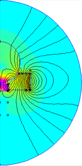
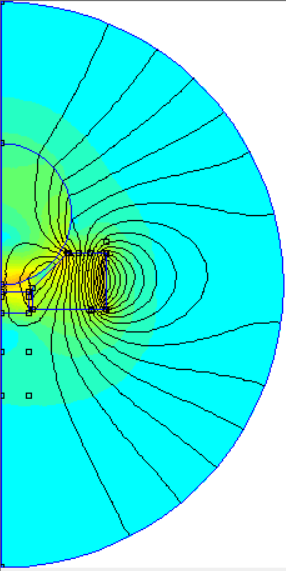
I have been playing around with FEMM to try and compare different rod magnet designs.
I am no expert but if I understand the results I have been seeing when playing around with different designs then hercek is right in that it can be very hard to get any magnetic flux though the ball when using a iron cup and housing. The majority of the flux will travel though the cup to the edge and jump to the housing skipping the ball.
One design that is simple to increase flux for a countersunk magnet is a small iron core inside the magnet. It is pure theory as I have not validated it but just the conical mag with 8N on the ball with the iron core it when up to 14N. That number is the integral of the Force Via Weighted Stress Tensor on the ball. Which I think represent the holding force on the ball.
Attached to renderings to try and demonstrate what I am talking about. The both have the same scale so you can see the differences in the flux.
|
Re: Haydns printed Mag Rods improved March 24, 2018 12:51PM |
Registered: 6 years ago Posts: 1,007 |
Quote
gambrose
I have been playing around with FEMM to try and compare different rod magnet designs.
I am no expert but if I understand the results I have been seeing when playing around with different designs then hercek is right in that it can be very hard to get any magnetic flux though the ball when using a iron cup and housing. The majority of the flux will travel though the cup to the edge and jump to the housing skipping the ball.
One design that is simple to increase flux for a countersunk magnet is a small iron core inside the magnet. It is pure theory as I have not validated it but just the conical mag with 8N on the ball with the iron core it when up to 14N. That number is the integral of the Force Via Weighted Stress Tensor on the ball. Which I think represent the holding force on the ball.
Attached to renderings to try and demonstrate what I am talking about. The both have the same scale so you can see the differences in the flux.
Not at all the profile I meant.
"A comical prototype doesn't mean a dumb idea is possible" (Thunderf00t)
|
Re: Haydns printed Mag Rods improved March 24, 2018 02:07PM |
Registered: 6 years ago Posts: 15 |
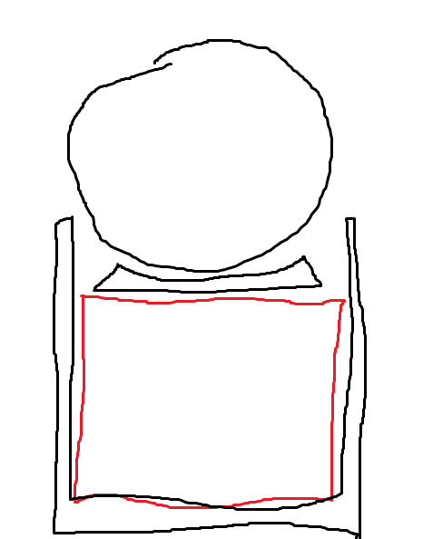
MKSA you described a "soft iron housing plus a soft iron cup". I understand that to be something like the sketch I uploaded with this post. I found that to be of benefit the housing needed to extend to be very close to the ball to be beneficial.
My profile I uploaded with my first post was intended as an alternative based on counter sunk magnets.
My profile I uploaded with my first post was intended as an alternative based on counter sunk magnets.
|
Re: Haydns printed Mag Rods improved March 24, 2018 04:01PM |
Registered: 10 years ago Posts: 732 |
Definition:
Second power of the integral of the magnetic field ( B ) over the ball surface divided by 2μ₀ corresponds to the holding force. Therefore you want to achieve as much magnetic flux going through the ball as possible. Then it will hold best.
Edit: Also note that you want most of the field to enter the ball in the direction of the diagonal rod axe. So that the forces cancel out as little as possible when the surface integral over the ball surface is computed. But the best situation from this point of view would mean big ball which would be heavy so there are some force/weight compromises to be made. Well as it is with the size of magnet, housing ...
Nice FEMM simulations, but they are not completely correct. They look like the seating/cup for the ball itself acts as the magnet. Try to simulate the situation you drew by hand. It should look better.
Edits in italic.
Edited 2 time(s). Last edit at 03/24/2018 04:17PM by hercek.
- Iron housing for the magnet is the iron part in which the magent is inserted (it is the bottom cylindrical black part on your drawing).
- Iron cup for the iron ball is the black iron part on your drawing which is between the ball and the magnet. This part should be fixed to the magnet and slip over the ball.
Second power of the integral of the magnetic field ( B ) over the ball surface divided by 2μ₀ corresponds to the holding force. Therefore you want to achieve as much magnetic flux going through the ball as possible. Then it will hold best.
Edit: Also note that you want most of the field to enter the ball in the direction of the diagonal rod axe. So that the forces cancel out as little as possible when the surface integral over the ball surface is computed. But the best situation from this point of view would mean big ball which would be heavy so there are some force/weight compromises to be made. Well as it is with the size of magnet, housing ...
Nice FEMM simulations, but they are not completely correct. They look like the seating/cup for the ball itself acts as the magnet. Try to simulate the situation you drew by hand. It should look better.
Edits in italic.
Edited 2 time(s). Last edit at 03/24/2018 04:17PM by hercek.
|
Re: Haydns printed Mag Rods improved March 24, 2018 04:51PM |
Registered: 6 years ago Posts: 15 |
Quote
hercek
Nice FEMM simulations, but they are not completely correct. They look like the seating/cup for the ball itself acts as the magnet. Try to simulate the situation you drew by hand. It should look better.
Edits in italic.
My FEMM simulation was using a design I was considering using counter sunk mags like these [www.supermagnete.de].
I did run a simulation matching the hand drawn one but found that it was very hard to get the lots of flux though the ball, as you predicted. I didn't keep that simulation so I can't post it but I may try and recreate it.
I think another issue I had was that the steel housing needs to be very close to the ball to at all effective. Which meant that it would severely limit movement of the joint. I was starting with 8mm diam mags as that was what I had bought. But then smaller mags means smaller flux.
Hence me trying out designs with the mag as the outer housing. The small steel core really seemed to concentrate the flux at the bottom of the ball.
Quote
hercek
Second power of the integral of the magnetic field ( B ) over the ball surface divided by 2μ₀ corresponds to the holding force. Therefore you want to achieve as much magnetic flux going through the ball as possible. Then it will hold best.
Edit: Also note that you want most of the field to enter the ball in the direction of the diagonal rod axe. So that the forces cancel out as little as possible when the surface integral over the ball surface is computed. But the best situation from this point of view would mean big ball which would be heavy so there are some force/weight compromises to be made. Well as it is with the size of magnet, housing ...
Edits in italic.
Thanks hercek this helps. I will try and workout how to get the correct force for my simulation from FEMM so I can optimise for the correct thing.
|
Re: Haydns printed Mag Rods improved March 24, 2018 05:29PM |
Registered: 10 years ago Posts: 732 |
Yes, at best, the housing should touch the ball the same way as the cup touches the ball.Quote
gambrose
I think another issue I had was that the steel housing needs to be very close to the ball to at all effective.
You can try to get some really thin cylindrical magnets (check what thin strong magnets are available) so that together with the housing it still does not have big diameter compared to the ball. Also housing probably does not need to have very thick wall (try only a millimeter or so). The problem with very thin walls is that the iron saturates with magnetic field and loses its permeability. If you do not want to compute it all analytically then just play with sizes in the simulator and select something which pushes as much flux through the ball as possible (preferably in the direction of the long diagonal rod axe). My default guess is that the simulator will take saturation in the account. It would not be much useful if it would not take it into account.
Well, you know my opinion: magnetic joints suck compared to proper ball joints. But if you have access to lathe you probably can design and produce something usable at higher speeds too ... after a lot of simulations with FEMM
|
Re: Haydns printed Mag Rods improved March 24, 2018 05:48PM |
Registered: 6 years ago Posts: 15 |
Quote
hercek
Well, you know my opinion: magnetic joints suck compared to proper ball joints. But if you have access to lathe you probably can design and produce something usable at higher speeds too ... after a lot of simulations with FEMM
What do you consider good ball joints? I.e. what should one look for when sourcing them and do you have any recommendations.
My reason for looking a mag balls is that most of the ball joints I've seen available have had reports of quite varied quality in terms of play. Although I still think mag joints are cool I am pragmatic enough to fit ball joints if I could find good ones for sensible money.
Edit:
Ignore me as I have just read your post [forums.reprap.org] in which you answered my question. Thanks
Edited 1 time(s). Last edit at 03/24/2018 05:50PM by gambrose.
|
Re: Haydns printed Mag Rods improved March 24, 2018 05:58PM |
Registered: 10 years ago Posts: 732 |
I tried only one kind: MP-Jet. I got a reference from a friend that they are good. I bought about 5 packs of them and the quality was consistent.
See: [forums.reprap.org]
If you would buy exactly the kind posted in the link then make sure you tighten them well. Catch the thick neck (just next to the M3 thread in thin pointed players. Press the players hard and tighten hard. Take care so that the players do not slip to the thinner part of the neck next to ball. You do not want to scratch the ball much ... or god forbid damage the plastic.
You want to tighten the ball joint well so that it does not come loose during printing.
Thanks god, I never bought the Traxxas crap which most people on this forum tried. It is a shame.
Edit: Ooops, you edited too late.
I meant the Traxas joints are shame to the rest of the ball joint industry
Edited 2 time(s). Last edit at 03/24/2018 06:10PM by hercek.
|
Re: Haydns printed Mag Rods improved March 27, 2018 08:35AM |
Registered: 6 years ago Posts: 1,007 |
Quote
gambrose
MKSA you described a "soft iron housing plus a soft iron cup". I understand that to be something like the sketch I uploaded with this post. I found that to be of benefit the housing needed to extend to be very close to the ball to be beneficial.
My profile I uploaded with my first post was intended as an alternative based on counter sunk magnets.
Indeed, it is what I meant, just the magnet diam smaller, the housing thicker and it tips closer to the ball and cupped as the cup on top. Could be made with the same tool. This to maximize the mag flux.
Again as a lifting magnet just made for a ball.
In the set up used in the current Delta, the mag flux is wasted in the air and impart close by Hal sensor in fans.
"A comical prototype doesn't mean a dumb idea is possible" (Thunderf00t)
|
Re: Haydns printed Mag Rods improved March 30, 2018 06:42PM |
Registered: 9 years ago Posts: 978 |
FYI, I just tried a simple experiment... I stuck a spare countersunk magnet (N35 I assume, 12x3mm) on the bottom of my vise, and hung a rod off it via a 10mm steel threaded ball. I then hung some weight off the other end of the rod. I gradually increased the weight until it dropped. This magnet held 542g. I then did the same thing with an N50 12x3mm flat disk magnet. Somewhat to my surprise, this second magnet held 762g. I had expected that with a single point of contact, it would hold less weight. So the N-number of the magnet is a really significant aspect of its holding power.
I've now ordered a whole bunch of N50-N52 magnets of various countersink geometries to see how the geometry affects the holding strength.
I've now ordered a whole bunch of N50-N52 magnets of various countersink geometries to see how the geometry affects the holding strength.

Sorry, only registered users may post in this forum.