New delta design with fixed ballscrews
Posted by klcjr89
|
New delta design with fixed ballscrews March 06, 2018 01:34AM |
Registered: 6 years ago Posts: 207 |
Hello, I came up with an interesting design that I'm not even sure if it would work, but I wanted to post it here to get positive feedback.
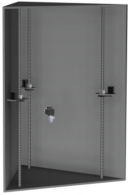
Basically, the design uses 1/2" thick Mic-6 plates for the bottom, top, and sides, and uses three stationary ballscrews that are press fitted into the top and bottom plates. The front plate will be lexan most likely.
The bed will be a seperate circular Mic-6 plate that will be insulated from the bottom plate with ceramic standoffs.
The ballnuts rotate around the ballscrew, lifting each carriage from the bottom, so the steppers move with the ballnuts.
I didn't model the effector and arms, but you should get the idea.
In another thread, someone mentioned the straightness of even C7 ballscrews is quite good, and could perhaps be used as the guide itself.
A couple concerns I have:
Thank you!
Renders:
Edited 4 time(s). Last edit at 03/06/2018 02:34AM by klcjr89.
Basically, the design uses 1/2" thick Mic-6 plates for the bottom, top, and sides, and uses three stationary ballscrews that are press fitted into the top and bottom plates. The front plate will be lexan most likely.
The bed will be a seperate circular Mic-6 plate that will be insulated from the bottom plate with ceramic standoffs.
The ballnuts rotate around the ballscrew, lifting each carriage from the bottom, so the steppers move with the ballnuts.
I didn't model the effector and arms, but you should get the idea.
In another thread, someone mentioned the straightness of even C7 ballscrews is quite good, and could perhaps be used as the guide itself.
A couple concerns I have:
- Will the inertia of the stepper movement cause the effector arms to rack or twist along the nozzle axis?
Will the weight of the stepper behind the axis of the screw cause the front of the stepper/carriage plate to lift upwards? Think of a seesaw.
Thank you!
Renders:
Edited 4 time(s). Last edit at 03/06/2018 02:34AM by klcjr89.
|
Re: New delta design with fixed ballscrews March 06, 2018 03:02AM |
Registered: 9 years ago Posts: 978 |
|
Re: New delta design with fixed ballscrews March 06, 2018 03:10AM |
Registered: 8 years ago Posts: 5,232 |
If you want to use Iglidur gliders as bearings for the ball nuts, as shown in the other thread, I see them wear out pretty quick. The bearing that holds the carrier/ballnut has to be playfree. IDK, if these backlash free ballnuts are good enough linear bearings as well. They are built to translate axial forces, not more.
Edit:
How would you keep the steppers from rotating around the screw? The effector arms have to be stabilized by the carrier, not the other way round...
Edited 2 time(s). Last edit at 03/06/2018 03:14AM by o_lampe.
Edit:
How would you keep the steppers from rotating around the screw? The effector arms have to be stabilized by the carrier, not the other way round...
Edited 2 time(s). Last edit at 03/06/2018 03:14AM by o_lampe.
|
Re: New delta design with fixed ballscrews March 06, 2018 03:12AM |
Registered: 6 years ago Posts: 207 |
Quote
frankvdh
Why not have the steppers rotate the screws? That way you aren't moving the mass of the motors, and the motor wiring doesn't need to move either. Motors attached to the top plate, and some 608ZZ or similar bearings in the bottom.
That’s been done before. I’m looking at fresh new designs.

|
Re: New delta design with fixed ballscrews March 06, 2018 03:41AM |
Registered: 9 years ago Posts: 483 |
|
Re: New delta design with fixed ballscrews March 06, 2018 10:19PM |
Registered: 7 years ago Posts: 507 |
I don't see the fuss about trying to keep the motor stationary, I'm guessing a screw that big has more inertia when spun up than the motor does when it has to move itself. I agree it means less wiring, but that may not be the goal here.
This is similar to the LISA Simpson Nicholas Seward built a while back. You can let the nut/carriage assembly rotate if you don't use parallel links to the effector. All you have to do is compensate for that rotation (and the translation along the ballscrew's axis it causes) in your kinematics. Not necessarily fun, but doable.
This is similar to the LISA Simpson Nicholas Seward built a while back. You can let the nut/carriage assembly rotate if you don't use parallel links to the effector. All you have to do is compensate for that rotation (and the translation along the ballscrew's axis it causes) in your kinematics. Not necessarily fun, but doable.
|
Re: New delta design with fixed ballscrews March 07, 2018 01:58AM |
Registered: 6 years ago Posts: 207 |
Quote
Trakyan
I don't see the fuss about trying to keep the motor stationary, I'm guessing a screw that big has more inertia when spun up than the motor does when it has to move itself. I agree it means less wiring, but that may not be the goal here.
This is similar to the LISA Simpson Nicholas Seward built a while back. You can let the nut/carriage assembly rotate if you don't use parallel links to the effector. All you have to do is compensate for that rotation (and the translation along the ballscrew's axis it causes) in your kinematics. Not necessarily fun, but doable.
So are you saying I should copy the LISA Simpson's effector/arm style to achieve my design?
Thanks!
|
Re: New delta design with fixed ballscrews March 08, 2018 06:18AM |
Registered: 8 years ago Posts: 3,525 |
I like the idea of the motors moving as its novel and whilst at first it might seem unnecessary, some benefits may emerge so its worth trying. My main concern is that your leadscrews will never be straight enough to prevent horrible wobble as you move up and down the axes. So you'll need to add a linear rail or rods or something in addition to the screws. Which begs the question could you use the screw and linear rail to supply positive and negative power and then have wireless stepper driver units on the motor carriages?
Simon Khoury
Co-founder of [www.precisionpiezo.co.uk] Accurate, repeatable, versatile Z-Probes
Published:Inventions
Simon Khoury
Co-founder of [www.precisionpiezo.co.uk] Accurate, repeatable, versatile Z-Probes
Published:Inventions
|
Re: New delta design with fixed ballscrews March 08, 2018 07:07AM |
Registered: 6 years ago Posts: 1,007 |
How about reading the Lisa 3D printer thread ?
[forums.reprap.org]
"A comical prototype doesn't mean a dumb idea is possible" (Thunderf00t)
[forums.reprap.org]
"A comical prototype doesn't mean a dumb idea is possible" (Thunderf00t)
|
Re: New delta design with fixed ballscrews March 08, 2018 11:21AM |
Registered: 6 years ago Posts: 207 |
Quote
DjDemonD
I like the idea of the motors moving as its novel and whilst at first it might seem unnecessary, some benefits may emerge so its worth trying. My main concern is that your leadscrews will never be straight enough to prevent horrible wobble as you move up and down the axes. So you'll need to add a linear rail or rods or something in addition to the screws. Which begs the question could you use the screw and linear rail to supply positive and negative power and then have wireless stepper driver units on the motor carriages?
Ballscrews are much straighter than leadscrews.
I already have, and it took awhile to do so.
|
Re: New delta design with fixed ballscrews March 08, 2018 01:05PM |
Registered: 6 years ago Posts: 207 |
@DJDemonD, I like the idea of using a linear shaft and the screw as positive and negative power for the stepper drivers fixed to the motor. I'm not sure how well WiFi or Bluetooth stepper drivers would work, they would probably need some kind of data buffer and be able to talk to the other two movement steppers.
There would also need to be a way to insulate the positive and negative from shorting out since the design plans to use metal for all of the structural plates.
I'm worried about having the steppers in the enclosure when printing materials like PEEK or Ultem. Liquid cooling the steppers is an option, since I planned on the hotend to be liquid cooled as well, but the tube routing might be messy.
Edited 4 time(s). Last edit at 03/08/2018 01:17PM by klcjr89.
|
Re: New delta design with fixed ballscrews March 08, 2018 02:22PM |
Registered: 8 years ago Posts: 3,525 |
Maybe there's a way to encode the position information onto the power lines like homeplug type systems. On the other hand maybe some wires to the motors isn't that much of a problem.
Simon Khoury
Co-founder of [www.precisionpiezo.co.uk] Accurate, repeatable, versatile Z-Probes
Published:Inventions
Simon Khoury
Co-founder of [www.precisionpiezo.co.uk] Accurate, repeatable, versatile Z-Probes
Published:Inventions
|
Re: New delta design with fixed ballscrews March 08, 2018 02:24PM |
Registered: 6 years ago Posts: 207 |
Quote
DjDemonD
Maybe there's a way to encode the position information onto the power lines like homeplug type systems. On the other hand maybe some wires to the motors isn't that much of a problem.
Another way would be to have a PCB with four copper tracks on it, and make an adapter that plugs into the stepper's port that has spring loaded contact pogo pins. There would be one PCB per stepper motor. The pogo pins will make contact with the tracks as each carriage moves up and down.
Edited 2 time(s). Last edit at 03/08/2018 02:26PM by klcjr89.
|
Re: New delta design with fixed ballscrews March 08, 2018 04:13PM |
Registered: 6 years ago Posts: 1,007 |
Quote
klcjr89
Quote
DjDemonD
Maybe there's a way to encode the position information onto the power lines like homeplug type systems. On the other hand maybe some wires to the motors isn't that much of a problem.
Another way would be to have a PCB with four copper tracks on it, and make an adapter that plugs into the stepper's port that has spring loaded contact pogo pins. There would be one PCB per stepper motor. The pogo pins will make contact with the tracks as each carriage moves up and down.
How about using Sawyer linear motors (works like a regular stepper but is flat), the tracks being the vertical guides ?
And all this in a closed vacuum tube. It would be called the HyperDelta printing at 10^6 mm/s

Edited 1 time(s). Last edit at 03/08/2018 04:17PM by MKSA.
"A comical prototype doesn't mean a dumb idea is possible" (Thunderf00t)
|
Re: New delta design with fixed ballscrews March 08, 2018 04:15PM |
Registered: 6 years ago Posts: 207 |
Quote
MKSA
Quote
klcjr89
Quote
DjDemonD
Maybe there's a way to encode the position information onto the power lines like homeplug type systems. On the other hand maybe some wires to the motors isn't that much of a problem.
Another way would be to have a PCB with four copper tracks on it, and make an adapter that plugs into the stepper's port that has spring loaded contact pogo pins. There would be one PCB per stepper motor. The pogo pins will make contact with the tracks as each carriage moves up and down.
How about using linear motors, the tracks being the vertical guides ?
And all this in a closed vacuum tube. It would be called the HyperDelta printing at 10^6 mm/s
Linear motors are too expensive, I explored that last year getting quotes from companies, namely H2W (they cost as much as a car).
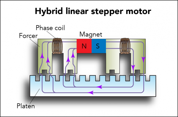
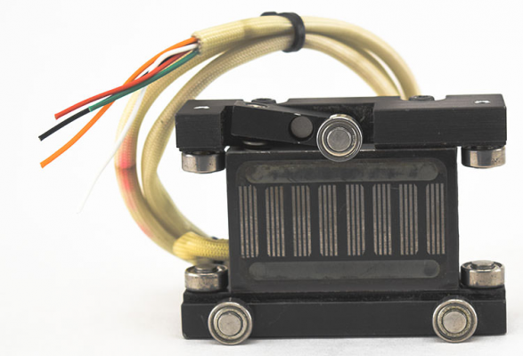
If we could figure out how to make them at home, that would be great. The platens can be sourced from McMaster-Carr using precision ground raw material, but they will need 'teeth' cut/ground in to them at a precise pitch. The forcer is a 2 phase electromagnet with ball-bearings that maintain a correct air gap.
The platens can be used structurally as well, having the ends press fitted into pockets in the top and bottom plates. It would make a for a sweet printer; the platens are the structure, the linear guides, and the means of movement using the forcers of course.
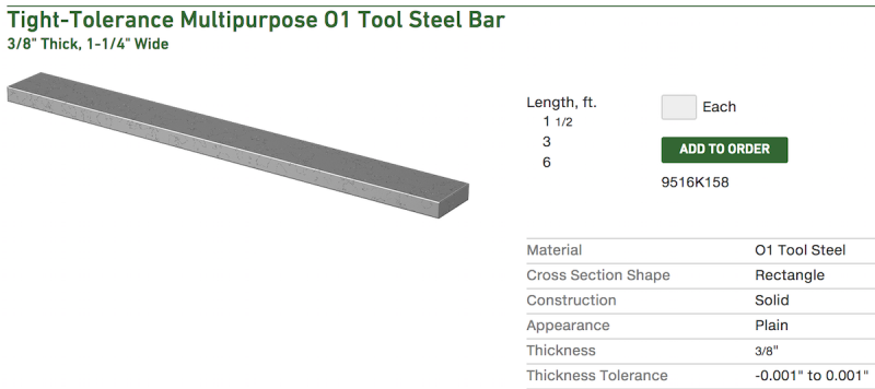
The raw material, which comes in lengths up to 6 ft.
 : [www.mcmaster.com]
O1 tool steel was selected as it has a better thickness tolerance than the low-carbon steel, and it comes in more usable (longer) lengths.
Note, the 3/8" thickness and 1-1/4" width were arbitrarily chosen based on the size H2W uses for their smallest platen. We could maybe get away with a lower thickness or even width bar. What matters is the amount of magnetic force that will keep each carriage held in place without losing steps with rapid movements (closed loop feedback probably overkill if we have plenty of magnetic force). An optical encoder in the forcer could read the teeth cut into the platen if someone truly feels like they need closed loop positioning.
I wonder, if a wet tile saw could cut the 'teeth' into the bar accurately enough if you build a simple indexing jig that references with the first 'tooth' cut into the bar. Like a spring-loaded ratchet and pawl. The pitch, depth, and perpendicularity of the teeth to the long edge of the bar are the most critical. Since tile saws don't have adjustable depth cutting like a table saw, some kind of sled would need made.
I saw that the flatness tolerance on the metric specified raw material is 127 microns per foot.
Edited 19 time(s). Last edit at 03/08/2018 05:22PM by klcjr89.
|
Re: New delta design with fixed ballscrews March 09, 2018 03:23AM |
Registered: 8 years ago Posts: 5,232 |
Quote
Linear motors are too expensive, I explored that last year getting quotes from companies, namely H2W (they cost as much as a car).
If we could figure out how to make them at home, that would be great. The platens can be sourced from McMaster-Carr using precision ground raw material, but they will need 'teeth' cut/ground in to them at a precise pitch. The forcer is a 2 phase electromagnet with ball-bearings that maintain a correct air gap.
How deep are the teeth? Would it be possible to etch them?
|
Re: New delta design with fixed ballscrews March 09, 2018 04:02AM |
Registered: 8 years ago Posts: 3,525 |
If you can make a linear motor that would be awesome. But... Isn't the point to get rid of wires, if the forcer is still in the carriage then you'll have to run cables to it.
Edited 1 time(s). Last edit at 03/09/2018 04:02AM by DjDemonD.
Simon Khoury
Co-founder of [www.precisionpiezo.co.uk] Accurate, repeatable, versatile Z-Probes
Published:Inventions
Edited 1 time(s). Last edit at 03/09/2018 04:02AM by DjDemonD.
Simon Khoury
Co-founder of [www.precisionpiezo.co.uk] Accurate, repeatable, versatile Z-Probes
Published:Inventions
|
Re: New delta design with fixed ballscrews March 09, 2018 04:32AM |
Registered: 6 years ago Posts: 1,007 |
Quote
DjDemonD
If you can make a linear motor that would be awesome. But... Isn't the point to get rid of wires, if the forcer is still in the carriage then you'll have to run cables to it.
Same system as used in the Tube and British RR
 No risk of a cow crossing so ?
"A comical prototype doesn't mean a dumb idea is possible" (Thunderf00t)
|
Re: New delta design with fixed ballscrews March 09, 2018 04:34AM |
Registered: 8 years ago Posts: 3,525 |
I was thinking have the coils in the track and permanent magnets in the carriage.
Edited 1 time(s). Last edit at 03/09/2018 04:34AM by DjDemonD.
Simon Khoury
Co-founder of [www.precisionpiezo.co.uk] Accurate, repeatable, versatile Z-Probes
Published:Inventions
Edited 1 time(s). Last edit at 03/09/2018 04:34AM by DjDemonD.
Simon Khoury
Co-founder of [www.precisionpiezo.co.uk] Accurate, repeatable, versatile Z-Probes
Published:Inventions
|
Re: New delta design with fixed ballscrews March 09, 2018 12:13PM |
Registered: 6 years ago Posts: 207 |
Quote
o_lampe
How deep are the teeth? Would it be possible to etch them?
About 1mm deep, so not really.
Quote
DjDemonD
I was thinking have the coils in the track and permanent magnets in the carriage.
It's far cheaper and easier to have the coils move with the forcer then to build several coils into the length of the platen.
Edited 1 time(s). Last edit at 03/09/2018 12:14PM by klcjr89.
|
Re: New delta design with fixed ballscrews March 09, 2018 03:55PM |
Registered: 6 years ago Posts: 1,007 |
BTW, I proposed this linear motor to tease you ! Have you seen and used them ? There is no way you could make them at home. They also run on an air cushion.
In fact, it could be used but as an X Y moving table, you put the bed on it and just need a hotend moving just in Z. A good start, this one: [www.ebay.com]
Edited 1 time(s). Last edit at 03/09/2018 03:56PM by MKSA.
"A comical prototype doesn't mean a dumb idea is possible" (Thunderf00t)
In fact, it could be used but as an X Y moving table, you put the bed on it and just need a hotend moving just in Z. A good start, this one: [www.ebay.com]
Edited 1 time(s). Last edit at 03/09/2018 03:56PM by MKSA.
"A comical prototype doesn't mean a dumb idea is possible" (Thunderf00t)
|
Re: New delta design with fixed ballscrews March 09, 2018 03:57PM |
Registered: 6 years ago Posts: 207 |
Quote
MKSA
BTW, I proposed this linear motor to tease you ! Have you seen and used them ? There is no way you could make them at home. They also run on an air cushion.
In fact, it could be used but as an X Y moving table, you put the bed on it and just need a hotend moving just in Z. A good start, this one: [www.ebay.com]
Actually, the air cushion ones are a different model, the ball bearings ones would work just fine, and I do have experience with them. You could make them at home with a surface grinder and a milling machine. [www.h2wtech.com]
Edited 2 time(s). Last edit at 03/09/2018 04:00PM by klcjr89.
|
Re: New delta design with fixed ballscrews March 10, 2018 02:51AM |
Registered: 8 years ago Posts: 5,232 |
|
Re: New delta design with fixed ballscrews March 10, 2018 03:43AM |
Registered: 6 years ago Posts: 1,007 |
Quote
klcjr89
Quote
MKSA
BTW, I proposed this linear motor to tease you ! Have you seen and used them ? There is no way you could make them at home. They also run on an air cushion.
In fact, it could be used but as an X Y moving table, you put the bed on it and just need a hotend moving just in Z. A good start, this one: [www.ebay.com]
Actually, the air cushion ones are a different model, the ball bearings ones would work just fine, and I do have experience with them. You could make them at home with a surface grinder and a milling machine. [www.h2wtech.com]
I know there are different models. The first one were riding on wheels !
A home that has the machines required are not the average home.
So, lead screws or linear motors ?
"A comical prototype doesn't mean a dumb idea is possible" (Thunderf00t)
|
Re: New delta design with fixed ballscrews March 10, 2018 11:33AM |
Registered: 6 years ago Posts: 207 |
Quote
o_lampe
In which way are these small bearings better than V-wheels and belt? You'd also need more bearings than shown, as you are moving vertical with no gravity holding the forcer down.
The precision ball bearings and the ground steel platen will be more precise than V slot which isn't ground.
Extra bearings aren't needed, the permanent magnet force keeps the bearings in contact with the platen. The platen works the same whether horizontal or vertical.
Quote
MKSA
So, lead screws or linear motors ?
Linear motors
 but maybe a seperate thread should be made for them to see how to pull it off so other printers can benefit from it.
Edited 5 time(s). Last edit at 03/10/2018 11:41AM by klcjr89.
|
Re: New delta design with fixed ballscrews March 10, 2018 03:37PM |
Registered: 6 years ago Posts: 207 |
I made a thread specifically on the discussion of linear motors here: [forums.reprap.org]
Sorry, only registered users may post in this forum.


