Non Flat printing plane
Posted by kkessler
|
Non Flat printing plane August 31, 2018 12:55PM |
Registered: 5 years ago Posts: 3 |
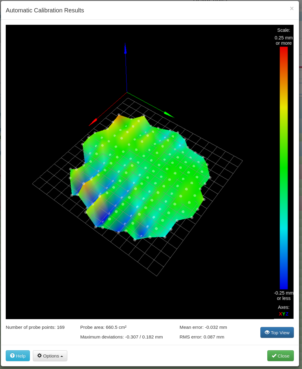
I've built a delta based on dc42's work (thanks for all the time you spent documenting it). Attached are the results of a mesh calibration, and the obvious thing you see is the wavy part towards high X values, with the peaks and valleys varying about .25mm and the "wavelength" (peak to peak measure) is 40mm. What I know about it is, that it is truly there, because I can measure the same waves manually with feeler gauges. It also doesn't seem to be in the bed. My bed is a 6 mm Al plate with the heater attached, topped with a 3 mm Al plate which holds a Buildtak flexplate. I can rotate all of those things around and the wave pattern does not move (I also tried a glass bed as well). I've also swapped around the arms of the delta, and the pattern does not change. Since the Z axis moves the most across as the print head traverses the waves, I thought that there could be some issues with the carriage movement over my cheap Chinese linear rails, but I certainly do not see or feel any wobble there.
My M665 and M666 look like:
Diagonal 360.000, delta radius 179.780, homed height 443.628, bed radius 177.8, X -0.351°, Y -0.288°, Z 0.000°
Endstop adjustments X0.67 Y0.64 Z-1.30, tilt X-0.14% Y0.06%
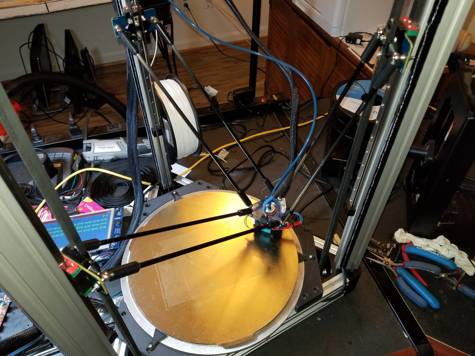
Does anyone have any suggestions as to my next debugging step? I attached a picture of my printer at X140 Y0 position to see if something jumps out at someone.
Thanks
My M665 and M666 look like:
Diagonal 360.000, delta radius 179.780, homed height 443.628, bed radius 177.8, X -0.351°, Y -0.288°, Z 0.000°
Endstop adjustments X0.67 Y0.64 Z-1.30, tilt X-0.14% Y0.06%
Does anyone have any suggestions as to my next debugging step? I attached a picture of my printer at X140 Y0 position to see if something jumps out at someone.
Thanks
|
Re: Non Flat printing plane August 31, 2018 04:29PM |
Registered: 10 years ago Posts: 14,672 |
That's a very common pattern - a crinkled-crisp like appearance, with ridges at one end of the X axis turning into valleys at the other end. It's caused by backlash in the mechanics, and it appears that way because the effector moves in opposite X directions on alternate rows while bed probing.
To fix it:
- Make sure the carriages move freely. With the effector and belts disconnected, they should drop under their own weight without being loose.
- Make sure the joints move freely. I use a little silicone grease on the magnetic joints.
- Make sure the belts are taut.
- Make sure the motor current is high enough, at least 60% of the rated current of the motor.
HTH David
Large delta printer [miscsolutions.wordpress.com], E3D tool changer, Robotdigg SCARA printer, Crane Quad and Ormerod
Disclosure: I design Duet electronics and work on RepRapFirmware, [duet3d.com].
|
Re: Non Flat printing plane September 01, 2018 02:03AM |
Registered: 8 years ago Posts: 5,232 |
Can you please try something for me?
Center the effector first.
When you roll the magnetic rods between thumb and finger, do they all give you the same friction?
It's important to pair up the rods until they give you the same feedback.
The reason might be differencies between the Delrin sleeves. Some of my Mag arms seem to make contact between magnet and ball stud.
The cup in the Delrin is too deep then. It can cause accuracy problems.
OTOH, if the Mag-Ballstud distance is too big, the holding force is ( much ) lower and can cause other problems.
When I found out, I was glad I'd ordered DIY kits from Haydn. That way I could sort out the bad ones. They were replaced by Haydn .
.
Center the effector first.
When you roll the magnetic rods between thumb and finger, do they all give you the same friction?
It's important to pair up the rods until they give you the same feedback.
The reason might be differencies between the Delrin sleeves. Some of my Mag arms seem to make contact between magnet and ball stud.
The cup in the Delrin is too deep then. It can cause accuracy problems.
OTOH, if the Mag-Ballstud distance is too big, the holding force is ( much ) lower and can cause other problems.
When I found out, I was glad I'd ordered DIY kits from Haydn. That way I could sort out the bad ones. They were replaced by Haydn
.
|
Re: Non Flat printing plane September 02, 2018 08:39PM |
Registered: 6 years ago Posts: 50 |
Quote
dc42
That's a very common pattern - a crinkled-crisp like appearance, with ridges at one end of the X axis turning into valleys at the other end. It's caused by backlash in the mechanics, and it appears that way because the effector moves in opposite X directions on alternate rows while bed probing.
To fix it:
- Make sure the carriages move freely. With the effector and belts disconnected, they should drop under their own weight without being loose.
- Make sure the joints move freely. I use a little silicone grease on the magnetic joints.
- Make sure the belts are taut.
- Make sure the motor current is high enough, at least 60% of the rated current of the motor.
HTH David
I though I would chime in here to provide some feedback;.
Firstly, the carriages should not freely move up and down under their own weight, if they do then there is play. There is often not much you can do with most linear rails (as most are not adjustable) but this is far easier to resolve with wheels. You want a constant preload on the guides/bearings and in the majority of the cases this should mean the carriage and effector will not fall under their own weight. This is an issues that is often overlooked when dealing with artifacts in delta printers. You want the carriages moving smoothly but with some resistance, it is this preload that prevents any movement while torque is being applied from the motor.
Avoid grease being used on your printer, there is to many particles created during printing and this is attracted to and collects in the grease and wears things faster (can also cause artifacts as things "bump" over the particles). There are of course some places you can't really avoid using a wet lube (lead screw), but try to use a dry lube silicon or teflon instead. Unfortunately this is one of the design flaws with mag balls, being only partially constrained, they are open to particles getting into the joint and migrating between the 2 surfaces (especially metallic particles thanks to the magnets), the irregularity in the mag ball mating surface is part of the problem here as well. The upside is they are always having a "preload" applied by the magnets, admittedly this can vary a fair amount from joint to joint.
Be careful on tightening belts where the axle shaft of the motor is only supported on one side (like 99% of delta printers). You want your belts nice and tight (approximately 30kg for 6m GT2 belt, or 60kg on a belt loop like most deltas) but putting the correct loading on an unsupported motor shaft results in the shaft bending over and creating irregular distance per step. So support the side of the motor shaft you slip the pulley over then crank down the tightness on the belts, if not then get them tight but do not tension them up fully.
Motor current shouldn't have any affect on the described issue. If there is no skip in layer or position then clearly the motors are more than capable of moving the effector around at their preset. I personally don't care about a little motor noise so running the motors at 100% of rated current is a non-issue. The motors are only going to draw the additional current if they are placed under enough load to require it so setting the motors at their rate currently isn't going to cause problems (assuming your stepper drivers can handle it). Keep in mind though, as you increase the motor current so will you increase electrical noise artifacts like "salmon skin", a non-issue with a Duet board but a serious issue on something like the cheap smoothie boards.
As to the OT issue;
- I would hazard a guess one of your pulleys is out of round (not centered on the shaft), as the motor rotates the distance between the center of the shaft and surface of the pulley changes as it rotates which means the step length changes. This normally results in ripples/rings that appear opposite to the tower with the issue (so X tower has rings almost coming out from it like a pond towards Y tower, then issue lies with Y tower).
-If you have used cheap linear rails then this is also a likely culprit, the small movements were are talking about will generally be too small for you to fell by hand but more than enough to show in the surface of a print.
- Next place I would check are the mag balls, as these are only partially constrained joints they allow for an effector to be "out of whack" due to misalignment of carriages or irregularities in arm lengths or mating surfaces. Decent rod ends prevent this from being able to happen as there is no play in the joint and the joint is 100% constrained in all directions. If you are out slightly on arm lengths with rod ends the effector and carriage will bind and not move freely, on a mag ball setup the joint will simply move out of constraint to make up for any variance with little to no resistance and zero binding. This shows up as rings in the print (on the horizontal surface) as the mag ball pivot points are moving position, dependent on where it is on the building plane, making regular and repeatable rings.
|
Re: Non Flat printing plane September 03, 2018 06:22AM |
Registered: 10 years ago Posts: 732 |
"Salmon skin" or "rings" on the walls of the prints are more likely related to incorrect decay mode for the used stepper. We had a thread about that here. Current has influence too but I would guess bad decay mode if it is not a duet board. Motor current can have significant influence on dynamic errors (errors due to high acceleration and rather low holding torque at microstep level) but these should not be significant when probing bed (there are only small forces there).
Eccentric pulley sounds probable. Also belt side with tooth over smooth idler can be a problem. Decay mode could be a problem if it would not be duet. Or if duet allows to select decay mode in software (configuration) then it may be set badly.
Eccentric pulley sounds probable. Also belt side with tooth over smooth idler can be a problem. Decay mode could be a problem if it would not be duet. Or if duet allows to select decay mode in software (configuration) then it may be set badly.
|
Re: Non Flat printing plane September 04, 2018 10:52AM |
Registered: 5 years ago Posts: 3 |
Thanks for all the help. It looks like the biggest problem I had was that my belts were not tight enough; that change got rid of the majority of the backlash. I still have enough backlash that the imperfections caused by that are greater than any real imperfections in the bed itself, so the mesh calibration actually makes things worse, but I can now get a good first layer now without anything more than the plain old delta calibration. I kind of wish I could run the mesh calibration in the opposite direction so I could mathematically cancel out the backlash a bit, and get a better feel flat the bed really is.
I'll continue to try to tweak the motion, but now my biggest issues is with my E3D Clogmaster 3000 hotend. I've never had a printer with a Bowden tube before, and I really don't like it.
I'll continue to try to tweak the motion, but now my biggest issues is with my E3D Clogmaster 3000 hotend. I've never had a printer with a Bowden tube before, and I really don't like it.
|
Re: Non Flat printing plane September 05, 2018 06:49AM |
Registered: 6 years ago Posts: 50 |

|
Re: Non Flat printing plane September 05, 2018 01:08PM |
Registered: 10 years ago Posts: 732 |
|
Re: Non Flat printing plane September 06, 2018 02:27AM |
Registered: 6 years ago Posts: 50 |
Quote
hercek
That may have bad impact on maximum acceleration because he uses magnetic joints.Quote
Redemptioner
Sounds like your next upgrade will be a floating extruder
Not by much if he does it right, in fact it may improve it depending on the mad balls used due to adding additional pre-load onto the joints, the improved control over retractions and the added ability to print flexible materials is easily worth the small impact it might have.
|
Re: Non Flat printing plane September 06, 2018 04:51AM |
Registered: 10 years ago Posts: 732 |
|
Re: Non Flat printing plane September 19, 2018 04:24PM |
Registered: 5 years ago Posts: 3 |
|
Re: Non Flat printing plane September 19, 2018 05:27PM |
Registered: 10 years ago Posts: 732 |
The upward pull on flying extruder will pull up platform and that will add preload on diagonal rods. It will help if some of the diagonal rods are not almost horizontal. You can also add independent preload with a spring along diagonal arms. This would help more because the direction of the force would be better.
The short bowden of flying extruder will damp high frequency (low amplitude) movement from the platform. But you will still need to pull the extruder cold end over longer distances and then change the direction. The biggest problem will be printing long narrow straight objects.
It will still suck compared to ball joints but there is a hope.
|
Re: Non Flat printing plane October 03, 2018 06:16PM |
Registered: 6 years ago Posts: 50 |
Should have no issues adding the tiny Zesty extruder, it is pretty light and compact but I have not tried it myself so my only reservation would be around it having enough torque to deal with "fast" printing or "thick" layers, even Bondtec extruders (which are simply not worth the money or the hype) suffer with a 1.2mm nozzle and over 100mm/s (which is really slow, for me anyways), they can't keep up even with an upgraded motor..... Remember that a floating extruder has some downsides, the main thing being its dependence on all your links not having any play in them, if they do (or your effect flexes like the Duet smart effector) then your nozzle will crash into the print after every retraction. This results in and increased join scar and other small blemishes on the outside of the print which to be honest you can live with, the one that becomes a pain is the build up of filament on the nozzle from it constantly being pushed into the print. You effector Mag balls won't be the issue as they should be pre-loaded with the flying extruder, the issue is with the joints on the carriages as they have to deal with the additional weight and the extruder tugging on the effector (non issues with rod ends).
Admittedly, most people are not after large layer heights or super fast printing, although I don't see the point of mag balls myself after having running several different versions unless you plan on changing out the hotend/effector on a regular basis. As I have previously mentioned, I removed and got rid of the mag ball setups as removing 6 bolts from rod ends only takes an extra 2 mins to do and improves not only the repeatability of the printed 100 fold compared to mag balls, it also improves the printers reliability and means you don't have to re-calibrate bed level after every change reducing time to setup and significantly reducing your blood pressure which can't be understated when dealing with multiple printers.
Admittedly, most people are not after large layer heights or super fast printing, although I don't see the point of mag balls myself after having running several different versions unless you plan on changing out the hotend/effector on a regular basis. As I have previously mentioned, I removed and got rid of the mag ball setups as removing 6 bolts from rod ends only takes an extra 2 mins to do and improves not only the repeatability of the printed 100 fold compared to mag balls, it also improves the printers reliability and means you don't have to re-calibrate bed level after every change reducing time to setup and significantly reducing your blood pressure which can't be understated when dealing with multiple printers.
Sorry, only registered users may post in this forum.