My Deltex build - input appreciated 
Posted by Nxt-1
|
My Deltex build - input appreciated January 31, 2019 06:02AM |
Registered: 5 years ago Posts: 10 |
Since a couple of weeks I have started designing my own hexagonal delta, which I have dubbed the Deltex. As design choices are still being made left and right I would love advice/input from others.
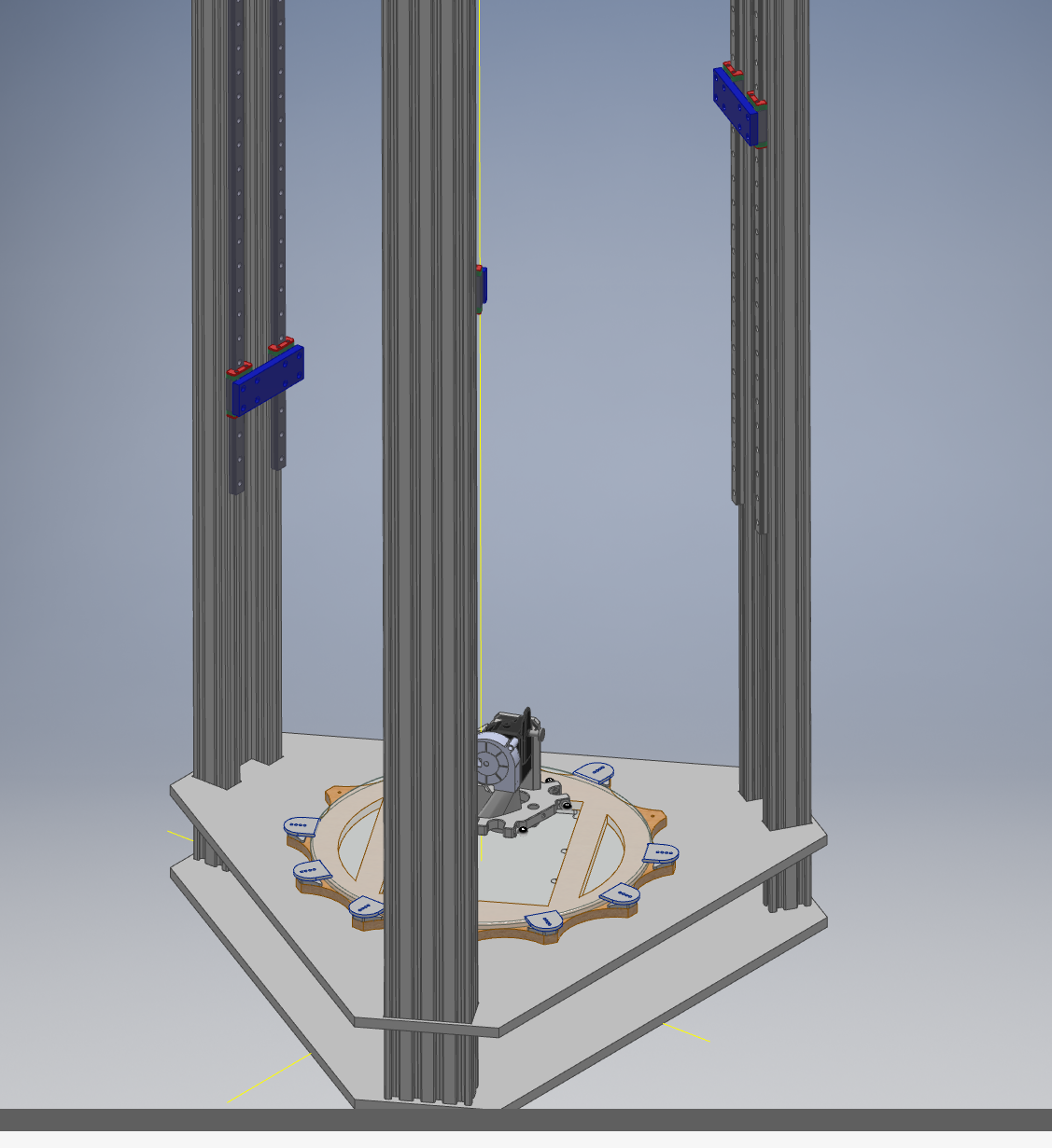
The 1st idea was to work with C-beam extrusions screwed to rather thick metal top and bottom plates. A pair of (Robotdigg) MGN12, 1 meter linear rails would be mounted per tower, with the belts running in the channel part of the 'C'. I wanted the C-beams to provide extra rigidity over regular square extrusions and the dual linear rails are a result of not having a center spot to mount a single one. See the attached picture for a early view on how things are looking now.
Recently however, I have been thinking the dual rails just add weight to the axis and a single rail would more then suffice in terms of rigidity as well. Therefore it might make more sense to possibly ditch the concept of aluminum extrusions all together, and go for a more closed design with full metal plates at the sides. Drilling holes, tapping etc, it would be more work, but that is not really and issue . A single rail would then be mounted straight to the metal plates.
A second point I would really love input on is arms, and especially how to construct them. I more or less decided on 6/4mm pultruded carbon rods, with MP-Jet ball links (here and here). I wonder how people generally attach their joints to the rods. Maybe a piece of M3 threaded rod stock in glued in the joint and that in turn epoxied in the CF rod? If this is a viable way to do it, would I need to look for high temp epoxy or does any regular suffice?
Edited 1 time(s). Last edit at 01/31/2019 06:02AM by Nxt-1.
The 1st idea was to work with C-beam extrusions screwed to rather thick metal top and bottom plates. A pair of (Robotdigg) MGN12, 1 meter linear rails would be mounted per tower, with the belts running in the channel part of the 'C'. I wanted the C-beams to provide extra rigidity over regular square extrusions and the dual linear rails are a result of not having a center spot to mount a single one. See the attached picture for a early view on how things are looking now.
Recently however, I have been thinking the dual rails just add weight to the axis and a single rail would more then suffice in terms of rigidity as well. Therefore it might make more sense to possibly ditch the concept of aluminum extrusions all together, and go for a more closed design with full metal plates at the sides. Drilling holes, tapping etc, it would be more work, but that is not really and issue
. A single rail would then be mounted straight to the metal plates.A second point I would really love input on is arms, and especially how to construct them. I more or less decided on 6/4mm pultruded carbon rods, with MP-Jet ball links (here and here). I wonder how people generally attach their joints to the rods. Maybe a piece of M3 threaded rod stock in glued in the joint and that in turn epoxied in the CF rod? If this is a viable way to do it, would I need to look for high temp epoxy or does any regular suffice?
Edited 1 time(s). Last edit at 01/31/2019 06:02AM by Nxt-1.
|
Re: My Deltex build - input appreciated January 31, 2019 07:53AM |
Registered: 10 years ago Posts: 732 |
I can comment on this quite well since I use MP-Jet.Quote
Nxt-1
A second point I would really love input on is arms, and especially how to construct them. I more or less decided on 6/4mm pultruded carbon rods, with MP-Jet ball links (here and here). I wonder how people generally attach their joints to the rods. Maybe a piece of M3 threaded rod stock in glued in the joint and that in turn epoxied in the CF rod? If this is a viable way to do it, would I need to look for high temp epoxy or does any regular suffice?
If you can source somewhere M3 hex slot bolts with conical head and an M3 nuts with one side conical as well then definitely go rather for these.
The point is the head of the M3 screw on the picture needs the side facing the thread chamfered (so that it is conical from the thread direction). This is needed so that the plastic arm does not hit the standard M3 screw head when rod is tilted more (at the edges of a print bed). Similar adjustment is needed on the other side of the rod end ball (I used an M3 nut which had one side chamfered so that it is conical as well.
The rod ends you have posted are OK too. The only problem with them is that they are pain to tighten. You need to use a thin pliers and tighten them on the wide part of the neck. It is not easy to do it without the pliers slipping.
Anwyay, I have a good experience with MP-Jet joints.
As for as making the rods:
Make all 6 rods in one jig. I used two M3 thread rods. One with right and the other with left thread. Cut about 2.5 cm of them and screw left threaded rod in one MP-Jet joint and the right threaded rod into the other MP-Jet joint. About 1.8 cm of the rod should stick out from each joint. Cut 5 mm external and 3 mm internal diameter carbon rod. Put epoxy on the threads and maybe a bit into the ends of the carbon rod and insert the thread rods into the carbon rod. Put whole diagonal rod into your jig and let it harden. I used a common epoxy (no high temperature one needed).
The need for both left and right threaded rods is so that you can adjust the length precisely afterwards. But I do not recommend adjusting it afterwards. It is not easy to achieve the same length precisely. You always need to do this against a jig.
|
Re: My Deltex build - input appreciated January 31, 2019 08:56AM |
Registered: 5 years ago Posts: 10 |
Quote
hercek
I can comment on this quite well since I use MP-Jet.Quote
Nxt-1
A second point I would really love input on is arms, and especially how to construct them. I more or less decided on 6/4mm pultruded carbon rods, with MP-Jet ball links (here and here). I wonder how people generally attach their joints to the rods. Maybe a piece of M3 threaded rod stock in glued in the joint and that in turn epoxied in the CF rod? If this is a viable way to do it, would I need to look for high temp epoxy or does any regular suffice?
If you can source somewhere M3 hex slot bolts with conical head and an M3 nuts with one side conical as well then definitely go rather for these.
The point is the head of the M3 screw on the picture needs the side facing the thread chamfered (so that it is conical from the thread direction). This is needed so that the plastic arm does not hit the standard M3 screw head when rod is tilted more (at the edges of a print bed). Similar adjustment is needed on the other side of the rod end ball (I used an M3 nut which had one side chamfered so that it is conical as well.
The rod ends you have posted are OK too. The only problem with them is that they are pain to tighten. You need to use a thin pliers and tighten them on the wide part of the neck. It is not easy to do it without the pliers slipping.
Anwyay, I have a good experience with MP-Jet joints.
As for as making the rods:
Make all 6 rods in one jig. I used two M3 thread rods. One with right and the other with left thread. Cut about 2.5 cm of them and screw left threaded rod in one MP-Jet joint and the right threaded rod into the other MP-Jet joint. About 1.8 cm of the rod should stick out from each joint. Cut 5 mm external and 3 mm internal diameter carbon rod. Put epoxy on the threads and maybe a bit into the ends of the carbon rod and insert the thread rods into the carbon rod. Put whole diagonal rod into your jig and let it harden. I used a common epoxy (no high temperature one needed).
The need for both left and right threaded rods is so that you can adjust the length precisely afterwards. But I do not recommend adjusting it afterwards. It is not easy to achieve the same length precisely. You always need to do this against a jig.
Is there any disadvantage of the rod ends I linked, other than the difficult tightening?
For the rods, you specify 5/3mm CF rods, would 4/3mm work as well? I'd love to avoid spending shipping cost on each order for the rod ends/epoxy/CF rods, so preferably I order everything though [www.lindinger.at] . They don't seem to offer 5/3mm sadly. It might be interesting that for the moment, I will be operating a fairly heavy effector (BondtechBMG + E3D-v6 on there). I'm open to other sources (I am EU based), but I have need seen other places that offer the MP-link joints.
For the actual fabrication of the rods, my understanding was that by using a jig to glue the rods, one would not need to adjust the length. Also if you by any chance have pics of how you did your jig, that would be awesome. At the moment I plan on just drilling two holes in a metal or acrylic plate where the rod ends can screw in. I imagine aligning the two parts of the rod end that connect to the rods have to be aligned carefully when gluing. Rotating them both to their end of travel (same as if the effector was the edge) would suffice I presume.
|
Re: My Deltex build - input appreciated January 31, 2019 09:49AM |
Registered: 10 years ago Posts: 732 |
The difficult tightening is the only disadvantage.Quote
Nxt-1
Is there any disadvantage of the rod ends I linked, other than the difficult tightening?
The carbon rods will be loaded almost exclusively in the direction of their long axe. Either tension or preasure (buckling).Quote
Nxt-1
For the rods, you specify 5/3mm CF rods, would 4/3mm work as well? I'd love to avoid spending shipping cost on each order for the rod ends/epoxy/CF rods, so preferably I order everything though [www.lindinger.at] . They don't seem to offer 5/3mm sadly. It might be interesting that for the moment, I will be operating a fairly heavy effector (BondtechBMG + E3D-v6 on there).
Prerequisities:
- bukcling: Young's modulus of Carbon fiber reinforced plastic (70/30 fibre/matrix, unidirectional, along grain) 181 GPa
- tension: tensile strength of Carbon fiber (unspecified) 1600 MPa
- 35 kN tension ideally; in practise we should consider about 3.5 kN only; but that is still plenty enough: your epoxy joints or plastic rod ends will fail sooner
- 5.4 kN under pressure (buckling); we should consider about 540 N only; that should be plenty enough as well.
Correct. I'm not advising adjusting them afterwards. You will not be able to adjust them as precisely as they were glued. But it is handy if you need to replace a rod end in the future. Then you do not need to redo the whole rod. If you cannot get easily a left-threaded M3 rod then do not bother. E.g. I could not get it bought in a simple hardware store. But I could easily buy a left handed thread cutter - so I cut the thread on a simple nailQuote
Nxt-1
For the actual fabrication of the rods, my understanding was that by using a jig to glue the rods, one would not need to adjust the length.
Yes, agreed. No pics, bu it is very simple. I just used a something like two Ø 2.9 mm holes (so that the M3 threads on the rods fit in reasonably tightly) in a hard wood. Just make sure you make the holes perpendicularly. Because you will probably drive a nail (or glue something) in the middle so that you can measure rod length precisely with only 15 cm long calipers ... if you do not have longer longer calipers. Measure the rods in the jig!Quote
Nxt-1
Also if you by any chance have pics of how you did your jig, that would be awesome. At the moment I plan on just drilling two holes in a metal or acrylic plate where the rod ends can screw in. I imagine aligning the two parts of the rod end that connect to the rods have to be aligned carefully when gluing. Rotating them both to their end of travel (same as if the effector was the edge) would suffice I presume.
|
Re: My Deltex build - input appreciated January 31, 2019 10:47AM |
Registered: 10 years ago Posts: 651 |
Here's a pic of the jig I used to build my rods.
https://reprap.org/forum/read.php?178,788150,796665#msg-796665
I did however forget to measure the distance between centers on the ends so I had to make an educated guess on the rod length.
Edit: There is space to do 2 rods at once, but I ended up only doing one at a time and using the same spot in the jig so I could be sure they were exactly the same.
Edited 1 time(s). Last edit at 01/31/2019 10:48AM by FA-MAS.
|
Re: My Deltex build - input appreciated January 31, 2019 03:28PM |
Registered: 10 years ago Posts: 14,672 |
A few suggestions:
- Getting the linear rails parallel to each other is vital. One way of doing this is to mount them on linear rails bolted to extrusions which are mounted in machined vertices. If you choose to bolt the rails to side plates instead, you need some other way to ensure that the rails are parallel (i.e. all accurately vertical in both directions).
- Consider using the Duet3D Smart Effector, if it's an appropriate size for your printer. As well as giving you precise dimensions for accurate geometry, it integrates a nozzle-contact Z probe for accurate auto calibration (and bed compensation if you need it). OK, I'm biased because I designed it.
- If you will be using a hexagonal frame or a similar arrangement, and you intend to use a Bowden extruder, consider mounting the extruder on a 4th rail so that its height can follow the movement of the effector. This will allow you to use a shorter Bowden tube. We've just added support for this in RepRapFirmware.
Large delta printer [miscsolutions.wordpress.com], E3D tool changer, Robotdigg SCARA printer, Crane Quad and Ormerod
Disclosure: I design Duet electronics and work on RepRapFirmware, [duet3d.com].
|
Re: My Deltex build - input appreciated February 01, 2019 03:20AM |
Registered: 10 years ago Posts: 732 |
|
Re: My Deltex build - input appreciated February 01, 2019 07:01AM |
Registered: 5 years ago Posts: 10 |
Quote
FA-MAS
Here's a pic of the jig I used to build my rods.
https://reprap.org/forum/read.php?178,788150,796665#msg-796665
I did however forget to measure the distance between centers on the ends so I had to make an educated guess on the rod length.
Edit: There is space to do 2 rods at once, but I ended up only doing one at a time and using the same spot in the jig so I could be sure they were exactly the same.
Thanks for the picture!
Quote
dc42
- Getting the linear rails parallel to each other is vital. One way of doing this is to mount them on linear rails bolted to extrusions which are mounted in machined vertices. If you choose to bolt the rails to side plates instead, you need some other way to ensure that the rails are parallel (i.e. all accurately vertical in both directions).
Yes, next to the added weight, achieving good parallelism during installation is something that pushes me towards a single rail design. Furthermore, it would probably be cheaper.
Quote
dc42
- Consider using the Duet3D Smart Effector, if it's an appropriate size for your printer. As well as giving you precise dimensions for accurate geometry, it integrates a nozzle-contact Z probe for accurate auto calibration (and bed compensation if you need it). OK, I'm biased because I designed it.
I have been considering integrating a Smart Effector when I design an updated version of my current effector. The Smart Effector's pcb would be mounted in a effector of my making, thus hopefully resulting in having the strain based Z-probe and being able to size the total effector how I desire. I believe the holes that would normally fit the magballs could function as mounting points for my own effector.
Quote
dc42
- If you will be using a hexagonal frame or a similar arrangement, and you intend to use a Bowden extruder, consider mounting the extruder on a 4th rail so that its height can follow the movement of the effector. This will allow you to use a shorter Bowden tube. We've just added support for this in RepRapFirmware.
I've been following the relevant post over on the Duet forum with great interest. However a flying extruder in something I would add at a later point in the build I think.
Yes, I'd like to avoid mag ball arms in the machine I am planning. But as I stated above, some kind of hybrid effector might be possible.Quote
hercek
Does not Smart Effector require magnetic joints?Quote
dc42
- Consider using the Duet3D Smart Effector, if it's an appropriate size for your printer
If so then it may be problem especially at higher accelerations since Nxt-1 wants to use some kind of heavy extruder.
|
Re: My Deltex build - input appreciated February 01, 2019 10:48AM |
Registered: 5 years ago Posts: 10 |
Quote
hercek
The carbon rods will be loaded almost exclusively in the direction of their long axe. Either tension or preasure (buckling).Quote
Nxt-1
For the rods, you specify 5/3mm CF rods, would 4/3mm work as well? I'd love to avoid spending shipping cost on each order for the rod ends/epoxy/CF rods, so preferably I order everything though [www.lindinger.at] . They don't seem to offer 5/3mm sadly. It might be interesting that for the moment, I will be operating a fairly heavy effector (BondtechBMG + E3D-v6 on there).
Prerequisities:If the above is true for the Ø 4/3 carbon rods you can buy then they can handle:
- bukcling: Young's modulus of Carbon fiber reinforced plastic (70/30 fibre/matrix, unidirectional, along grain) 181 GPa
- tension: tensile strength of Carbon fiber (unspecified) 1600 MPa
I would risk it with your Ø 4/3 carbon rods even when I never used them myself.
- 35 kN tension ideally; in practise we should consider about 3.5 kN only; but that is still plenty enough: your epoxy joints or plastic rod ends will fail sooner
- 5.4 kN under pressure (buckling); we should consider about 540 N only; that should be plenty enough as well.
Update: the shop actually does offer 5/3mm CF tubes. I've just sent them an email confirming these are pultruded, which I believe is most desirable in this use case.
|
Re: My Deltex build - input appreciated February 01, 2019 06:29PM |
Registered: 10 years ago Posts: 732 |
|
Re: My Deltex build - input appreciated April 10, 2019 05:39AM |
Registered: 5 years ago Posts: 10 |
The construction of my frame should be completed either this or next week. It's time to start cutting and gluing the rods (I've decided on 500mm total length), is there anything I should keep in mind while making them? Any common mistakes I can avoid. I am using a jig (two holes in the top plate of my printer frame)
|
Re: My Deltex build - input appreciated May 28, 2019 03:40AM |
Registered: 5 years ago Posts: 10 |
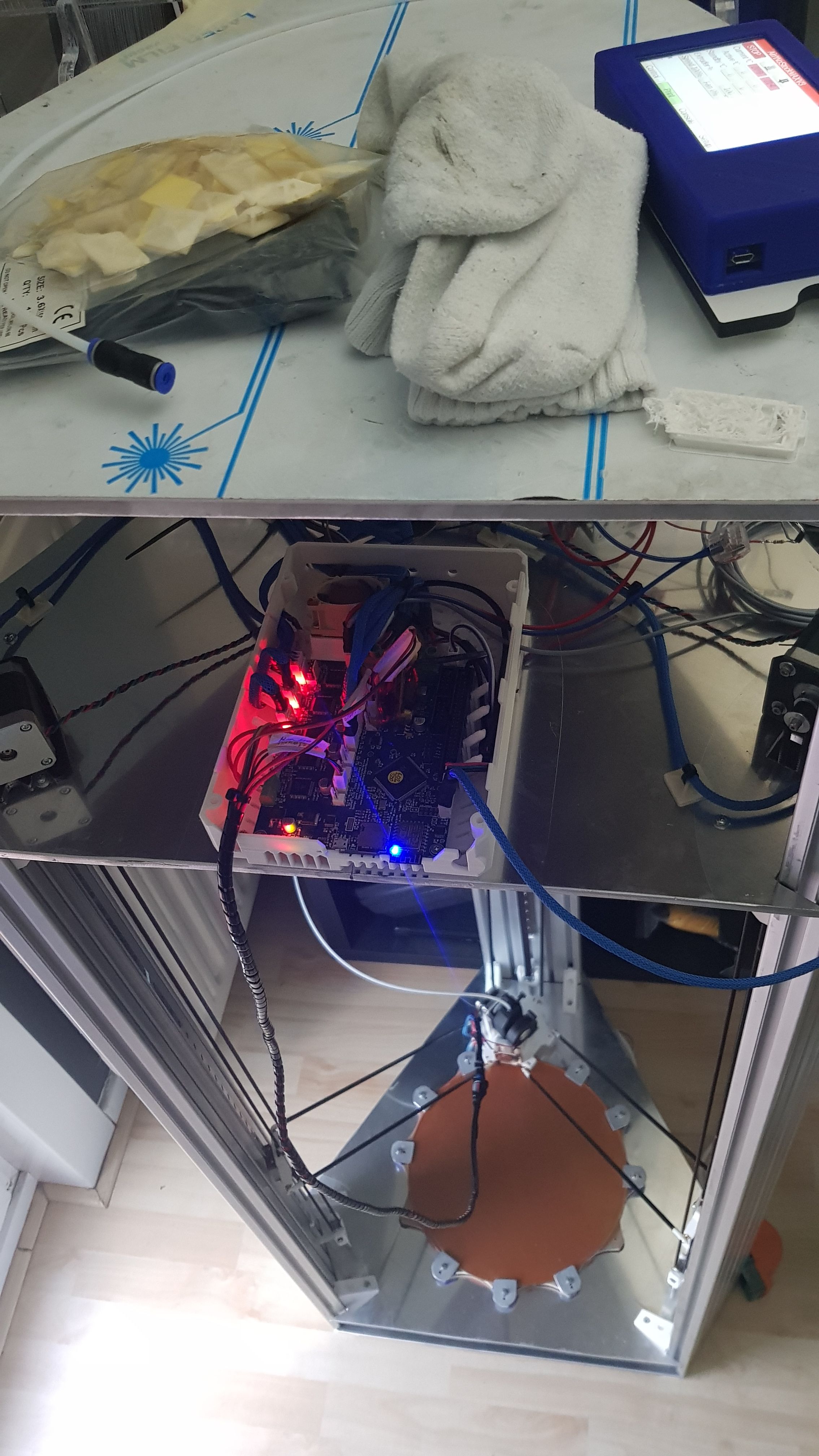
My new printer is finally up and running. There are still numerous changes and improvements planned but at least it can move, heat and extrude now .
Edited 2 time(s). Last edit at 05/28/2019 03:44AM by Nxt-1.
.- Complete the PN_ON level inverting circuit to control the Meanwell PSU
- Add grounding to the tower steppers and maybe some extra frame grounding as well
- Add a 4th tower axis and move the extruder to it
- Change from FSR's as a Z-probe to a Smart Effector
- Move the old camera and proxy setup from the Pi Zero W I as using to a model 3 B+
- Order and install a larger silicone heater + figure out what new bed I plan to use underneath the PEI
- Get a Super Volcano kit
Edited 2 time(s). Last edit at 05/28/2019 03:44AM by Nxt-1.
|
Re: My Deltex build - input appreciated May 30, 2019 03:35PM |
Registered: 5 years ago Posts: 10 |
|
Re: My Deltex build - input appreciated May 30, 2019 03:46PM |
Registered: 10 years ago Posts: 732 |
Sorry, only registered users may post in this forum.