Prints from new Delta not square
Posted by blt3dp
|
Prints from new Delta not square March 25, 2019 11:48AM |
Registered: 10 years ago Posts: 651 |
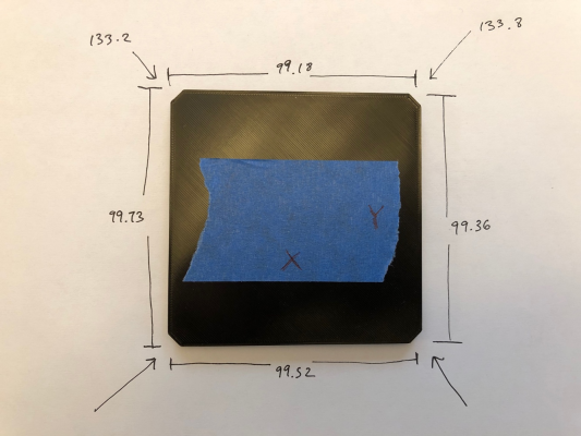
Hey All, I thought I'd start a new thread instead of adding to my build log. I'm having an issue with prints not being square.
Just a little overview of my build, top and bottom plates are CNC waterjet cut MIC6. The verticals are milled square and to the same length by a machine shop. Here's my thread with build details.
https://reprap.org/forum/read.php?178,788150,846429#msg-846429
Here's some details on the issue.
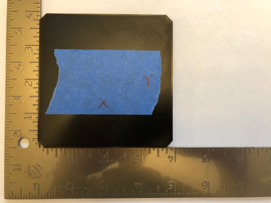
In this picture, I've put it up against a square. You can't really see it in the photo, but there is a very tiny gap between the square and the upper left corner of the print.
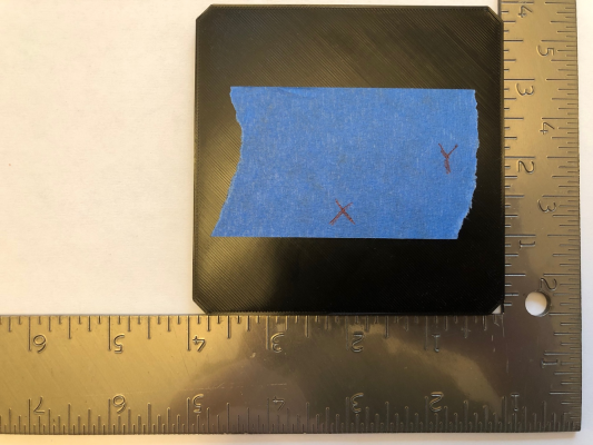
Here's the square on the other side. Same deal except the gap is on the lower right corner of the print.
Here's my config.g
Edited 7 time(s). Last edit at 03/25/2019 12:01PM by FA-MAS.
Just a little overview of my build, top and bottom plates are CNC waterjet cut MIC6. The verticals are milled square and to the same length by a machine shop. Here's my thread with build details.
https://reprap.org/forum/read.php?178,788150,846429#msg-846429
Here's some details on the issue.
In this picture, I've put it up against a square. You can't really see it in the photo, but there is a very tiny gap between the square and the upper left corner of the print.
Here's the square on the other side. Same deal except the gap is on the lower right corner of the print.
Here's my config.g
; Configuration file for Duet WiFi (firmware version 1.17 to 1.19)
; executed by the firmware on start-up
;
; generated by RepRapFirmware Configuration Tool v2 on Sun Jan 20 2019 07:13:04 GMT-0800 (PST)

; General preferences
G90                                          ; Send absolute coordinates...
M83                                          ; ...but relative extruder moves
M665 R165.000 L333.886 B145.000 H363.920     ; Set delta radius, diagonal rod length, printable radius and homed height
M666 X0 Y0 Z0                                ; Put your endstop adjustments here, or let auto calibration find them

; Network
M550 P"My Printer"                           ; Set machine name
M552 P0.0.0.0 S1                             ; Enable network and acquire dynamic address via DHCP
M586 P0 S1                                   ; Enable HTTP
M586 P1 S0                                   ; Disable FTP
M586 P2 S0                                   ; Disable Telnet

; Drives
M569 P0 S1                                   ; Drive 0 goes forwards
M569 P1 S1                                   ; Drive 1 goes forwards
M569 P2 S1                                   ; Drive 2 goes forwards
M569 P3 S1                                   ; Drive 3 goes forwards
M350 X16 Y16 Z16 E16 I1                      ; Configure microstepping with interpolation
M92 X200.00 Y200.00 Z200.00 E837.00          ; Set steps per mm
M566 X1200.00 Y1200.00 Z1200.00 E120.00      ; Set maximum instantaneous speed changes (mm/min)
M203 X7200.00 Y7200.00 Z7200.00 E7200.00     ; Set maximum speeds (mm/min)
M201 X3000.00 Y3000.00 Z3000.00 E200.00      ; Set accelerations (mm/s^2)
M906 X1100.00 Y1100.00 Z1100.00 E900.00 I30  ; Set motor currents (mA) and motor idle factor in per cent
M84 S30                                      ; Set idle timeout

; Axis Limits
M208 Z0 S1                                   ; Set minimum Z

; Endstops
M574 X2 Y2 Z2 S1                             ; Set active high endstops

; Z-Probe
M558 P8 R0.4 H5 F300 I1 T1800                ; Set Z probe type to effector and the dive height + speeds
G31 P500 X0 Y0 Z-0.1                         ; Set Z probe trigger value, offset and trigger height
M557 R106.066 S20                            ; Define mesh grid

; Heaters
M307 H0 B0 S1.00                             ; Disable bang-bang mode for the bed heater and set PWM limit
M305 P0 T100000 B3950 R4700                  ; Set thermistor + ADC parameters for heater 0
M143 H0 S130                                 ; Set temperature limit for heater 0 to 120C
M305 P1 T100000 B4388 C7.060000e-8 R4700     ; Set thermistor + ADC parameters for heater 1
M307 H1 A417.2 C302.9 D6.9 S0.70 V24.4 B0    ; Set PID parameters for heater 1
M143 H1 S290                                 ; Set temperature limit for heater 1 to 285C

; Fans
M106 P1 T45 H1

; Tools
M563 P0 D0 H1                                ; Define tool 0
G10 P0 X0 Y0 Z0                              ; Set tool 0 axis offsets
G10 P0 R0 S0                                 ; Set initial tool 0 active and standby temperatures to 0C

; Custom settings are not configured
Edited 7 time(s). Last edit at 03/25/2019 12:01PM by FA-MAS.
|
Re: Prints from new Delta not square March 26, 2019 05:35AM |
Registered: 10 years ago Posts: 732 |
Possible causes of this:
1) towers are not parallel to each other
2) diagonal rods do not have the same length
3) a line connecting balls on carriages is not equidistant to the line connecting the corresponding balls on the effector platform (meaning the carriages are slightly rotated)
The Z-height probing based calibration methods suck at detecting these (they suck especially at detecting problems 2 and 3).
Edited 1 time(s). Last edit at 03/26/2019 06:05AM by hercek.
|
Re: Prints from new Delta not square March 26, 2019 09:55AM |
Registered: 10 years ago Posts: 651 |
I'm pretty confident in my tower positions, the top and bottom plates are CNC WaterJet cut. The holes to mount the vertical towers are precisely positioned. Although, the holes could be slightly tighter around the screws. There's a slight chance for a minuscule amount of twist, but care was taken to avoid that. Also the verticals were milled square and to the same length. My frame is far more accurate than anything assembled with parts from Robotdigg could be. And others are getting precise prints out of them.
The carriages are a concern, as they're kind of junk. I had to file down the mount points for the rods to make the distance between them the same as on the effector. I did also measure to make sure the rod ends were at the same height. but truthfully, I'm still not to confident they didn't rotate a bit when i tightened the screws down.
I previously was confident in my assembled rods, but I'm not so much anymore. I took them all off and made a jig to fit them in. Some were only slightly off.
I also have a bubble level on the effector, I watched it as I did a G32. I noticed that it remained almost exactly centered except for when it got near the X tower, the bubble would move away from center and go toward the Y tower. Leading me to believe it tilts as it get towards.
So, I'm done with the Robotdigg junk. The only thing I'll be using is the carriages, and their only purpose will be to fasten the belts to the bearing blocks.
I've ordered a smart effector and mag arms. We'll see how that does.
Edited 1 time(s). Last edit at 03/26/2019 09:59AM by FA-MAS.
|
Re: Prints from new Delta not square April 03, 2019 09:57AM |
Registered: 10 years ago Posts: 651 |
Got the smart effector all installed and hooked up. I had no idea the magnets were so strong, I'm not concerned at all about them coming loose anymore. In fact, I really like the ability to easily disconnect them as well as how tidy everything is with the smart effector.
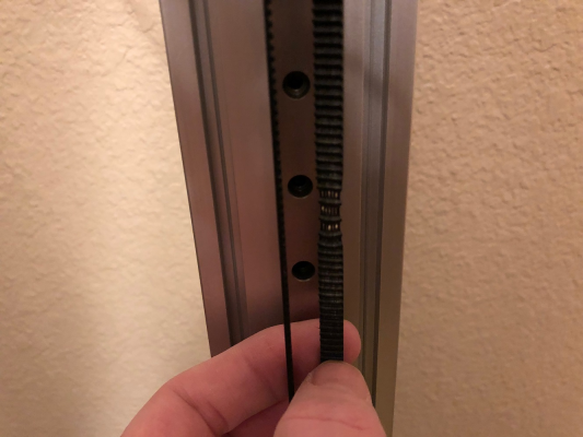
Though I was running a test print and the head crashed into the print. I slept on it and thought I'd double check my belt tension and noticed the belt on the Z tower was looser than the others. Then I found this. Think this might have caused an issue with the prints not being square? I'm going to replace that belt tonight and run another test print.
Edited 1 time(s). Last edit at 04/03/2019 10:30AM by FA-MAS.
|
Re: Prints from new Delta not square April 03, 2019 08:00PM |
Registered: 10 years ago Posts: 651 |
|
Re: Prints from new Delta not square April 04, 2019 03:00AM |
Registered: 10 years ago Posts: 14,672 |
Are you using steel cored belts? If so, replace them with glass or Kevlar cored ones. Steel cored ones fracture when used with small pulleys. E3D sells genuine Gates belts.
Large delta printer [miscsolutions.wordpress.com], E3D tool changer, Robotdigg SCARA printer, Crane Quad and Ormerod
Disclosure: I design Duet electronics and work on RepRapFirmware, [duet3d.com].
Large delta printer [miscsolutions.wordpress.com], E3D tool changer, Robotdigg SCARA printer, Crane Quad and Ormerod
Disclosure: I design Duet electronics and work on RepRapFirmware, [duet3d.com].
|
Re: Prints from new Delta not square April 04, 2019 09:43AM |
Registered: 10 years ago Posts: 651 |
They're fiberglass belts, I did see in DJDemonD's thread that he had problems with steel cored belts so I avoided them. The test print completed. Things are much closer now, but still not quite right. When I auto calibrate and then issue M665, it tells me that there's a very miniscule rotation of the X and Y towers. Similar values to those posted in the first post of this thread. I also had a thought of the rails not being perfectly centered on the extrusion, I mean I used a printed jig which I thought would center them all exactly, but when I measured with calipers, it looks like they might be slightly off. I would think that if the rails were shifted to one side, it wouldn't mesh well with the assumption that they're centered at the vertex of the triangle the frame makes. Also I suppose there could be slight tilt caused by the top or bottom being not as centered as the other.
Think either of those I should pursue?
Edited 1 time(s). Last edit at 04/04/2019 10:03AM by FA-MAS.
Think either of those I should pursue?
Edited 1 time(s). Last edit at 04/04/2019 10:03AM by FA-MAS.
|
Re: Prints from new Delta not square April 15, 2019 12:41PM |
Registered: 10 years ago Posts: 651 |
Still having a problem with this. I've since had new top and bottom plates cut. They've been adjusted to mimic the exact geometry of dc42's kossel. Eg. mine was previously based off of his printer with 355mm horizontals. Now it matches with the current 390mm horizontals.
In doing so, I had to completely rebuild it. I verified the vertical rails are perpendicular to the top and bottom plates as well as the print bed. I've also got the duet smart effector, carriages and 360mm mag arms. Those I know at this point are accurately built.
The only thing I'm not confident of is that the linear rails are centered on the extrusion. I will be adjusting that as well as ensuring the belt tension is right and i get the right amount of movement from the carriages.
Anything else I should check?
|
Re: Prints from new Delta not square April 15, 2019 04:30PM |
Registered: 10 years ago Posts: 732 |
Linear rails not being cantered on the extrusion is not that important. This kind of error will only lead to a slightly different virtual tower position and that can be easily calibrated out. Or if you have top of the rail moved to different direction than the bottom of the rail then it will tilt the whole virtual tower. Most firmware cannot calibrate this out but it can be done. If you are unsure then prefer to move both top and the bottom of the rail to one side. That should be easy to do. It will lead to having the whole virtual tower moved in radial direction but that does not matter. It is trivial do calibrate out.
If you need precise XY dimensions then a bigger problem is when your towers are rotated along their log axe or when carriages are rotated along any axe but the one going through the ball joints.
If you need precise XY dimensions then a bigger problem is when your towers are rotated along their log axe or when carriages are rotated along any axe but the one going through the ball joints.
|
Re: Prints from new Delta not square April 15, 2019 04:46PM |
Registered: 10 years ago Posts: 651 |
I only see a couple of things causing this, the top of the linear rail not being perfectly vertically aligned with the bottom one thus causing a tilt in in the virtual tower position or a slight rotation of the tower around the long axis
I know it's not the actual extrusion being tilted. The machine is built incredibly accurate. I'd have to refer to the pics in my other thread, but in the center of my top and bottom plates there's a hole pattern that mimics the mount points at the vertices of the triangle where you would mount the towers. This is so that I could mount them one at a time in the center against the cast tooling plate and use a large square (12 inch) to verify they were milled to sit perpendicular. They definitely are perpendicular. When I mount the verticals to the bottom plate, I can then sit the top plate on it and everything lines up exactly, I don't have to tweak anything.
That being said, the holes in the top and bottom plates for the M5 screws are slightly oversized to allow for the screw to fit through easier, i suppose it could allow a slight amount of rotation about the long axis. But I'm matching the face of the extrusion up with the face of the top and bottom plates, it's unlikely. I can measure that by measuring distances between the towers.
|
Re: Prints from new Delta not square April 15, 2019 10:28PM |
Registered: 10 years ago Posts: 651 |
I think I may have gotten it sorted out. I did end up designing an "alignment helper" tool that I mounted to my extrusions. 1 at the top and 1 at the bottom of the linear rails on both sides, so 4 total. They had screws through them that would pinch the linear rail and could adjust them either way as well as hold them in place while I tightened them. I then used calipers to make sure they were centered and tightened them down.
Ran the same gcode I was previously for a 100x100mm square. This time I stopped it half way and measured it on the bed after it cooled. Only 0.012 difference between measurements if I measure Y axis on either side and the X is perfect. Diagonals measure perfect. I'm thinking that's as close as I'll be able to get it without like really meticulously making sure things are perfect within microns.
Time to do some prints.
|
Re: Prints from new Delta not square April 17, 2019 08:56PM |
Registered: 10 years ago Posts: 651 |
Think I may have found another issue, I don't know if my pulleys are concentric, or round. I was chasing down the source of some noise when moving and noticed the flanges of the pulleys move in a wavy fashion and each rotation it rubs the belt. they were supposed to be good pulleys, but they look garbage now that I see that. Looks like I'm going to order some official gates pulleys.
Sorry, only registered users may post in this forum.


