Delta printer ball joints, let's talk!
Posted by 3Dpassion
|
Re: Delta printer ball joints, let's talk! December 25, 2019 04:00AM |
Registered: 10 years ago Posts: 14,672 |
If your printer runs RepRapFirmware then small differences in scale can be corrected using M579.
Large delta printer [miscsolutions.wordpress.com], E3D tool changer, Robotdigg SCARA printer, Crane Quad and Ormerod
Disclosure: I design Duet electronics and work on RepRapFirmware, [duet3d.com].
Large delta printer [miscsolutions.wordpress.com], E3D tool changer, Robotdigg SCARA printer, Crane Quad and Ormerod
Disclosure: I design Duet electronics and work on RepRapFirmware, [duet3d.com].
|
Re: Delta printer ball joints, let's talk! December 25, 2019 06:08AM |
Admin Registered: 11 years ago Posts: 3,096 |
Okay, I will start a new topic that is specific to this printer so it's easier to get some help instead of replying under other's topics.
http://www.marinusdebeer.nl/
http://www.marinusdebeer.nl/
|
Re: Delta printer ball joints, let's talk! May 10, 2021 11:48AM |
Registered: 9 years ago Posts: 294 |
My apologies for undigging this topic . But searching around for ideas..
Guys i did used some magnets too on my recent build. I am thinking of going back to balljoints as i do have some lying around. My main problem is that the magnets are super strong and i have the impression that they force my effector to tilt ....!
On the other hand my rods was 3.2mm inside so i couldn't attach the balljoints that are M3 , unless i would use something like a helicoil. My magnets are rated 1kq per unit ( that's what i ve been told ).
Edited 1 time(s). Last edit at 05/10/2021 11:50AM by Gaou.
Delta Printer
Duet 0.8.5 firmware 1.19
|
Re: Delta printer ball joints, let's talk! May 10, 2021 12:25PM |
Registered: 10 years ago Posts: 14,672 |
I use the magnetic rods with Delrin ends and ball studs from Haydn Huntley, which are claimed to have a pulling force of about 1kgf. They work very well but they do need to be lubricated every few months (I use a little silicone grease). If you've made the magnetic joints yourself, it's vital that the magnets don't actually touch the ball studs.
Large delta printer [miscsolutions.wordpress.com], E3D tool changer, Robotdigg SCARA printer, Crane Quad and Ormerod
Disclosure: I design Duet electronics and work on RepRapFirmware, [duet3d.com].
Large delta printer [miscsolutions.wordpress.com], E3D tool changer, Robotdigg SCARA printer, Crane Quad and Ormerod
Disclosure: I design Duet electronics and work on RepRapFirmware, [duet3d.com].
|
Re: Delta printer ball joints, let's talk! May 10, 2021 03:47PM |
Registered: 9 years ago Posts: 294 |
thanks David for ur kind reply...! Always so helpful...
i ve notice that as one of my mistakes...! i am looking for a workaround on this ...! i am not sure that i will find a solution though ...! looking for magballs and rods in europe as the only place that have them both is usa.
Delta Printer
Duet 0.8.5 firmware 1.19
Quote
dc42
.. it's vital that the magnets don't actually touch the ball studs.
i ve notice that as one of my mistakes...! i am looking for a workaround on this ...! i am not sure that i will find a solution though ...! looking for magballs and rods in europe as the only place that have them both is usa.
Delta Printer
Duet 0.8.5 firmware 1.19
|
Re: Delta printer ball joints, let's talk! May 10, 2021 06:23PM |
Registered: 5 years ago Posts: 33 |
|
Re: Delta printer ball joints, let's talk! May 11, 2021 01:05PM |
Registered: 9 years ago Posts: 294 |
Quote
jcs
I use "mouse tape" on mine. It's thin adhesive teflon tape and lasts for years.
i ll look for Haydn Huntley’s set. But untill then that sounds a brilliant idea. Only thing left is to find that tape here in local market. Thanks a lot for pointing.
Delta Printer
Duet 0.8.5 firmware 1.19
|
Re: Delta printer ball joints, let's talk! May 11, 2021 02:15PM |
Registered: 12 years ago Posts: 1,450 |
@Gaou,
When you said that you thought that the magnets were too strong It sparked a memory. Unless the geometry is severely out of whack there should not be a condition where the effector is tilted away from where it was set - and yet that was exactly what I have seen when I first designed my own magnetic rod ends. It turned out that I had made a bad design choice: I made iron cups out of high permeability iron for the balls to sit into but found that this gave much worse holding and the effector moved all over the place. The explanation is that the ball could move sideways on the cup and slide up the wall. Think of trying to separate two strong disk magnets - pulling them apart is very difficult yet sliding them sideways is easy and results in a weakened connection where you can pull them apart quite easily. The diagram below shows this effect.
Replacing the iron cups with Delrin cups with the middle bit a little less than 1mm thick gave about 1.25kg pull-apart with the below parts.
Steel balls with M4 thread [www.ebay.co.uk]
Cylindrical magnets 8mm x 8mm longN54 Edit: N45 [www.ebay.co.uk]
Extreme pressure grease works very well for lubrication and I have found no wear and the joints still move freely a year since they were last greased. I use this grease [www.ebay.co.uk]
Mike
Edited 1 time(s). Last edit at 05/11/2021 02:17PM by leadinglights.
When you said that you thought that the magnets were too strong It sparked a memory. Unless the geometry is severely out of whack there should not be a condition where the effector is tilted away from where it was set - and yet that was exactly what I have seen when I first designed my own magnetic rod ends. It turned out that I had made a bad design choice: I made iron cups out of high permeability iron for the balls to sit into but found that this gave much worse holding and the effector moved all over the place. The explanation is that the ball could move sideways on the cup and slide up the wall. Think of trying to separate two strong disk magnets - pulling them apart is very difficult yet sliding them sideways is easy and results in a weakened connection where you can pull them apart quite easily. The diagram below shows this effect.

Replacing the iron cups with Delrin cups with the middle bit a little less than 1mm thick gave about 1.25kg pull-apart with the below parts.
Steel balls with M4 thread [www.ebay.co.uk]
Cylindrical magnets 8mm x 8mm long
Extreme pressure grease works very well for lubrication and I have found no wear and the joints still move freely a year since they were last greased. I use this grease [www.ebay.co.uk]
Mike
Edited 1 time(s). Last edit at 05/11/2021 02:17PM by leadinglights.
|
Re: Delta printer ball joints, let's talk! May 11, 2021 02:49PM |
Registered: 9 years ago Posts: 294 |
i dont have a cup . I do have some countersink magnets glueed with instant glue on my effector and on top of that there are the the balls....! i have read what you are telling me some minutes ago on the forum . Seems very right . I do not know if that's the case on mine since there is equal force in a certain diameter on the ball. You can see that in the post for the delta i ve made.
I ll look more on that tomorrow to be sure.
Delta Printer
Duet 0.8.5 firmware 1.19
I ll look more on that tomorrow to be sure.
Delta Printer
Duet 0.8.5 firmware 1.19
|
Re: Delta printer ball joints, let's talk! May 11, 2021 10:14PM |
Registered: 4 years ago Posts: 285 |
Quote
Gaou
i dont have a cup . I do have some countersink magnets glueed with instant glue on my effector and on top of that there are the the balls....! i have read what you are telling me some minutes ago on the forum . Seems very right . I do not know if that's the case on mine since there is equal force in a certain diameter on the ball. You can see that in the post for the delta i ve made.
I ll look more on that tomorrow to be sure.
Mike and myself are in total agreement that a proper ball riding directly on a proper magnet, with the proper lubricant works more than fine. After all, a piston ring in an automobile engine is slapping back and forth at roughly 30 MPH (the ring, not the car), for potentially hundreds of thousands of miles.
Also, see here:
[reprap.org]
Edited 1 time(s). Last edit at 05/11/2021 10:21PM by rq3.
|
Re: Delta printer ball joints, let's talk! May 12, 2021 05:46AM |
Registered: 12 years ago Posts: 1,450 |
There is nothing inherently wrong with metal to metal for rubbing parts although I am not sure the plating on magnets is a good candidate. I prefer to use a plastic cup - Delrin in my printers
I did a quick test with a countersunk magnet and a ball to check if the results were the same as with my iron cup test. On first results it doesn't look like having a ball nestled in the cup of the magnet is a good way of doing a magnetic ball joint.
The magnets are stuck to a steel bar and the hammer is an 8mm steel ball that has been silver soldered to a brass rod. When pulled with a spring balance it appeared to release cleanly at about 500 grams but when the rod was pulled up by hand it came up about 1/3 of the way out with relatively little pressure, then slid up the side of the cone to the lip where it held on for a bit - possibly when I was applying about 500 grams of pull, before finally releasing. Surprisingly this "soft disconnect" seemed less clear with only one countersunk magnet - possibly the stack of magnets reinforces the strength of the face more than in the recessed hole.
If I get a chance I will build a test rig to measure the way that different geometries of magnetic joints release - I have the good fortune to have a bunch of suitable force gauges and other equipment.
Mike
I did a quick test with a countersunk magnet and a ball to check if the results were the same as with my iron cup test. On first results it doesn't look like having a ball nestled in the cup of the magnet is a good way of doing a magnetic ball joint.

The magnets are stuck to a steel bar and the hammer is an 8mm steel ball that has been silver soldered to a brass rod. When pulled with a spring balance it appeared to release cleanly at about 500 grams but when the rod was pulled up by hand it came up about 1/3 of the way out with relatively little pressure, then slid up the side of the cone to the lip where it held on for a bit - possibly when I was applying about 500 grams of pull, before finally releasing. Surprisingly this "soft disconnect" seemed less clear with only one countersunk magnet - possibly the stack of magnets reinforces the strength of the face more than in the recessed hole.
If I get a chance I will build a test rig to measure the way that different geometries of magnetic joints release - I have the good fortune to have a bunch of suitable force gauges and other equipment.
Mike
|
Re: Delta printer ball joints, let's talk! May 12, 2021 03:08PM |
Registered: 5 years ago Posts: 33 |
Just for anyone that's interested, I used the same geometry as leadinglights shows except I used spherical magnets as well, instead of steel balls. Along with the aforementioned mouse tape that works fine with no shifting. Of course you have to make sure the magnetic poles are optimally aligned.
Edited 1 time(s). Last edit at 05/12/2021 03:11PM by jcs.
Edited 1 time(s). Last edit at 05/12/2021 03:11PM by jcs.
|
Re: Delta printer ball joints, let's talk! May 12, 2021 03:57PM |
Registered: 4 years ago Posts: 285 |
Quote
jcs
Just for anyone that's interested, I used the same geometry as leadinglights shows except I used spherical magnets as well, instead of steel balls. Along with the aforementioned mouse tape that works fine with no shifting. Of course you have to make sure the magnetic poles are optimally aligned.
Magnetically, there two issues with using a steel cup. The side of the cup stuck to the magnet gets the opposite pole induced into it. If the magnet face is, say, north, the sticking face of the steel cup is south. Of course, the other face of the cup is then north, and the ball is trying to stick to a north faced steel cup with a north faced magnet just under it. Not good. Anyone who has tried to statically levitate some magnets has seen this effect.
Also, a disc magnet with a hole in it has a hole (a weak spot) in the center of its field. By placing a solid cylindrical magnet under the disc, of the same diameter and a length equal to the diameter, the hole is filled, and actually concentrates in the center. A magnetic steel ball will then stick ferociously to the countersunk disc, and will preferentially self center.
I use 440C stainless steel bearing balls. They are relatively cheap, extremely hard, and extremely accurate in both size and roundness. I used to use teflon pads, but now run the balls directly on the nickel plated magnets, with grease in the magnet cavity. No visible wear after thousands of prints.
|
Re: Delta printer ball joints, let's talk! May 13, 2021 06:43AM |
Registered: 12 years ago Posts: 1,450 |
Firstly I must apologize if my postings in this thread were somewhat ambiguous. My experience and tests indicate that iron cups and even the countersunk in countersunk magnets are a bad thing and not suitable for magnetic joints in delta printers.
As far as I can make out, the exact opposite applies, i.e. adding an extra magnet may make for a higher strength before release, but it does less to center the ball which seems to climb up the cone to the front face easier although this awaits some testing to get numbers and graphs.
My personal preference is for a cup made of a non-magnetic material - bronze or plastic for example, with a very thin center and a strong magnet.
The tests will be delayed though as I have to make up a bunch of cages to keep the birds off the fruit in the allotment.
Mike
Edited 1 time(s). Last edit at 05/13/2021 06:44AM by leadinglights.
Quote
rq3
.............................. Also, a disc magnet with a hole in it has a hole (a weak spot) in the center of its field. By placing a solid cylindrical magnet under the disc, of the same diameter and a length equal to the diameter, the hole is filled, and actually concentrates in the center. A magnetic steel ball will then stick ferociously to the countersunk disc, and will preferentially self center..........................
As far as I can make out, the exact opposite applies, i.e. adding an extra magnet may make for a higher strength before release, but it does less to center the ball which seems to climb up the cone to the front face easier although this awaits some testing to get numbers and graphs.
My personal preference is for a cup made of a non-magnetic material - bronze or plastic for example, with a very thin center and a strong magnet.

The tests will be delayed though as I have to make up a bunch of cages to keep the birds off the fruit in the allotment.
Mike
Edited 1 time(s). Last edit at 05/13/2021 06:44AM by leadinglights.
|
Re: Delta printer ball joints, let's talk! May 13, 2021 05:48PM |
Registered: 5 years ago Posts: 33 |
Quote
rq3
Magnetically, there two issues with using a steel cup. The side of the cup stuck to the magnet gets the opposite pole induced into it. If the magnet face is, say, north, the sticking face of the steel cup is south. Of course, the other face of the cup is then north, and the ball is trying to stick to a north faced steel cup with a north faced magnet just under it. Not good. Anyone who has tried to statically levitate some magnets has seen this effect.
I'm not sure I exactly follow what you're getting at.
The steel cup serves as a pole-piece for the cylindrical magnet due to the steel having a much higher permeability than air. This is a typical arrangement for magnetic devices. (I have some commercial experience in this area) So lets say the cylindrical magnets N pole is touching the pole piece, Then the cup end will also be N. When the S pole of the spherical magnet approaches the cup it will be very strongly attracted. Now, it is a good idea to keep the pole piece as short as possible. I didn't bother to model the magnetic flux when I first designed this and I no longer have access to the software; but I assure you this design works fine. I've been using it with no (magnetic) problems on two deltas for years. I admit when I first built it, I wasn't sure how well it would work as the arm angle increased; but as it developed that wasn't a problem.
The disadvantage of this design is that it is more difficult to make.
|
Re: Delta printer ball joints, let's talk! May 13, 2021 07:21PM |
Registered: 4 years ago Posts: 285 |
Quote
jcs
Quote
rq3
Magnetically, there two issues with using a steel cup. The side of the cup stuck to the magnet gets the opposite pole induced into it. If the magnet face is, say, north, the sticking face of the steel cup is south. Of course, the other face of the cup is then north, and the ball is trying to stick to a north faced steel cup with a north faced magnet just under it. Not good. Anyone who has tried to statically levitate some magnets has seen this effect.
I'm not sure I exactly follow what you're getting at.
The steel cup serves as a pole-piece for the cylindrical magnet due to the steel having a much higher permeability than air. This is a typical arrangement for magnetic devices. (I have some commercial experience in this area) So lets say the cylindrical magnets N pole is touching the pole piece, Then the cup end will also be N. When the S pole of the spherical magnet approaches the cup it will be very strongly attracted. Now, it is a good idea to keep the pole piece as short as possible. I didn't bother to model the magnetic flux when I first designed this and I no longer have access to the software; but I assure you this design works fine. I've been using it with no (magnetic) problems on two deltas for years. I admit when I first built it, I wasn't sure how well it would work as the arm angle increased; but as it developed that wasn't a problem.
The disadvantage of this design is that it is more difficult to make.
I don't use a spherical magnet. It serves no function in this application, and demands that you precisely align the poles. If it works for you, carry on. But understand that a permeable iron pole piece is NOT another magnet. The effect on the field is very different, and still makes my head hurt to think about. A piece of magnetically permeable iron on a magnet is not the same as a magnet of the same size, in terms of the external magnetic field. The difference can be both subtle and dramatic. Halbach arrays and stepper motors are good examples. The array would not work if alternating magnets were replaced by iron pole pieces, and the stepper would not work if the iron rotor were replaced by magnets.
Also, lets all define our terms here. Making a stack of toroidal magnets ( the typical countersunk discs designed to be mounted to a surface with a screw) is VERY different, magnetically, than placing the same toroid on a SOLID cylindrical magnet, or an iron pole piece. They are three completely different magnetic circuits, and introducing a mating magnetic sphere makes it so complex that it gets you into an unsolvable three body problem.
Basically, that why you can't statically levitate any combination of permanent magnets (Earnshaw's theorem), which you guys are trying to violate. If you succeed, I want stock in your company!
Edited 3 time(s). Last edit at 05/13/2021 07:50PM by rq3.
|
Re: Delta printer ball joints, let's talk! May 14, 2021 04:08AM |
Registered: 9 years ago Posts: 483 |
 With springs you can adjust the amount of tension. You just need 6 hands to install them if you don't use magnets as well.
|
Re: Delta printer ball joints, let's talk! May 14, 2021 07:30AM |
Registered: 12 years ago Posts: 1,450 |
@jcs, I had not thought about a spherical magnet but have some in my box of oddities so did some very cursory checks and I lean towards rq3's opinion that good alignment with a cylindrical magnet is problematic. I did however find that you can get an excellent magnetic attraction for very little mass by using two cylindrical magnets with a magnetic ball between them - the total mass of this joint would be about 60% of a magnet and steel ball. In an actual magnetic joint, this would involve having the ball magnet not being attached to either cylindrical magnet and being free to self-align.
Although I haven't tried a magnetic ball with a steel cup - or pole piece if you will, some further quick tests reinforce my opinion that they should be avoided. The practical problem is that the effective length of the joint can be lengthened during deceleration as the ball can still be in contact with the cup but not at the center - see the earlier photos with the countersunk magnets.
Mike
|
Re: Delta printer ball joints, let's talk! May 17, 2021 10:12AM |
Registered: 12 years ago Posts: 1,450 |
From previous experience, I was already happy that using a steel cup on a magnetic joint is not a good choice, but I didn't know the scale of the problem. A good way to put this into some sort of scale is to make a model and take measurements of the force required to move the ball from its seated position in the cup.
The rig consists of a steel disk (18mm dia x 3mm thick) to simulate a ball but in just 2 dimensions; a pole piece with a cup of the same radius as the disk on one end and with non-magnetic (Paxolin) centering cheeks on the other. Both the pole piece and the disk were fitted with a stack (4) of magnets. I used a force gauge to measure the pull to disengage the disk from the pole piece both along the axis of the pole pieces and at an angle of 30°.
The results were that the ball to steel cup lost full seating at less than 60% of to force that the ball and plastic cup held. When the force was applied at an angle, the more common situation in a Delta printer, the holding force of the ball and steel cup was less than 40% as strong as the ball and plastic cup.
The last picture shows the position of the ball when it has just lost full seating - the force pulling the ball back is about 250 grams at this position. That there is a path for the magnetic field is clear in this picture.
Mike
The rig consists of a steel disk (18mm dia x 3mm thick) to simulate a ball but in just 2 dimensions; a pole piece with a cup of the same radius as the disk on one end and with non-magnetic (Paxolin) centering cheeks on the other. Both the pole piece and the disk were fitted with a stack (4) of magnets. I used a force gauge to measure the pull to disengage the disk from the pole piece both along the axis of the pole pieces and at an angle of 30°.

The results were that the ball to steel cup lost full seating at less than 60% of to force that the ball and plastic cup held. When the force was applied at an angle, the more common situation in a Delta printer, the holding force of the ball and steel cup was less than 40% as strong as the ball and plastic cup.

The last picture shows the position of the ball when it has just lost full seating - the force pulling the ball back is about 250 grams at this position. That there is a path for the magnetic field is clear in this picture.
Mike
|
Re: Delta printer ball joints, let's talk! May 17, 2021 06:01PM |
Registered: 4 years ago Posts: 285 |
Dammit, Mike! Now you've done it! You actually made me go and think about all this! My primitive vector analysis indicates that there can't be any side load on the arms of a delta printer. The force from the carriage to the effector is always axial, either compression or tension. If this were not true, a hang printer wouldn't work, and neither would a delta, since the effector would head in directions that make my head hurt.
Theoretically, the arms on a delta could be replaced with infinitely thin, infinitely stiff, threads (like a hang printer, but there the weight of the effector keeps the threads under tension at all times). All of the vectors go through the centers of the balls, except when there is a large change in acceleration (jerk, in physics), which puts a rotational force on the ball (as if the arms were each replaced by two threads, one each at the top and bottom of each ball). I do know I've accidentally driven my delta at over 3 G's without the balls de-coupling (due to a Marlin error that still exists [UBL leveling verification printing]).
I'll have to go and slap a force gauge on my arm assemblies at various angles, which I've never done. I'll report back. Thanks again for making me think about my assumptions!
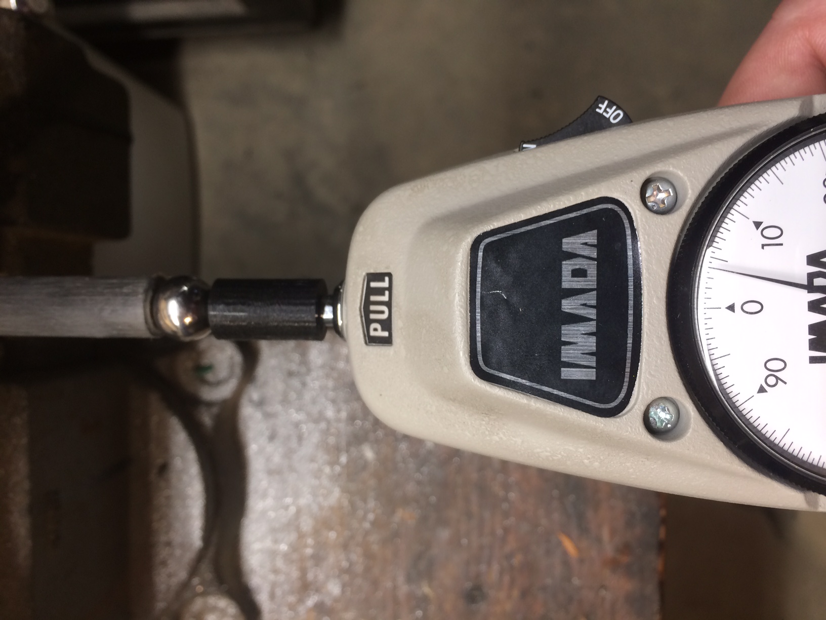
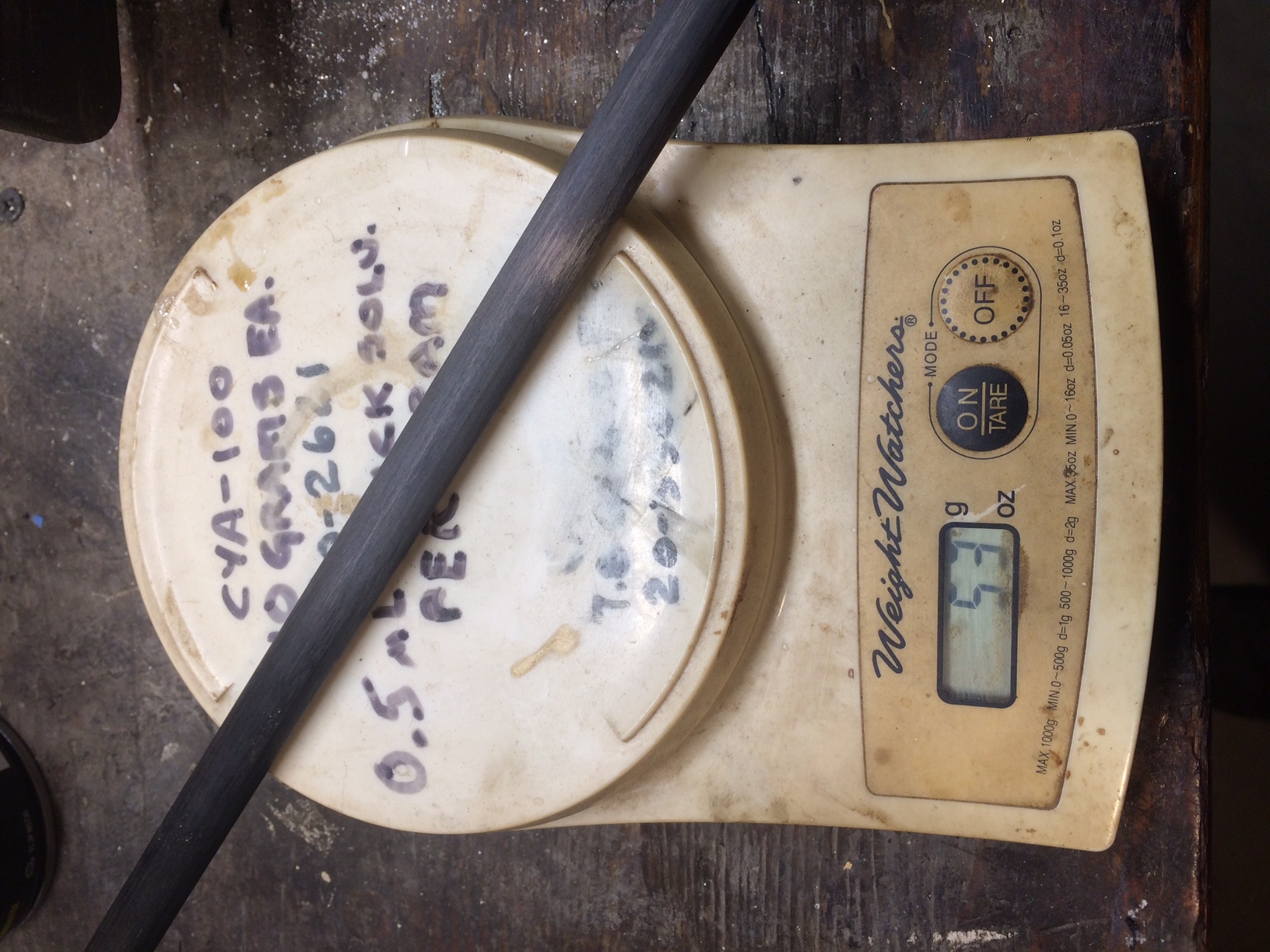
EDIT: Photos attached. Each of my arms weighs 53 grams, including the two carriage and effector balls and their mounting hardware. The straight on attachment force is 4 pounds (1.8 kilograms). At 90 degrees, the attachment is 2.75 pounds (1.25 kilograms).
Edited 1 time(s). Last edit at 05/17/2021 07:12PM by rq3.
Theoretically, the arms on a delta could be replaced with infinitely thin, infinitely stiff, threads (like a hang printer, but there the weight of the effector keeps the threads under tension at all times). All of the vectors go through the centers of the balls, except when there is a large change in acceleration (jerk, in physics), which puts a rotational force on the ball (as if the arms were each replaced by two threads, one each at the top and bottom of each ball). I do know I've accidentally driven my delta at over 3 G's without the balls de-coupling (due to a Marlin error that still exists [UBL leveling verification printing]).
I'll have to go and slap a force gauge on my arm assemblies at various angles, which I've never done. I'll report back. Thanks again for making me think about my assumptions!
EDIT: Photos attached. Each of my arms weighs 53 grams, including the two carriage and effector balls and their mounting hardware. The straight on attachment force is 4 pounds (1.8 kilograms). At 90 degrees, the attachment is 2.75 pounds (1.25 kilograms).
Edited 1 time(s). Last edit at 05/17/2021 07:12PM by rq3.
|
Re: Delta printer ball joints, let's talk! May 18, 2021 09:57AM |
Registered: 12 years ago Posts: 1,450 |
@rq3, With an attachment force of 1.25kg to 1.8kg I don't think that you will be having any problems with your magnetic joints failing to remain properly seated.
Jerk is likely to be the main area of problems as normal acceleration has only the mass of the effector to contend with and six magnets to hold everything together. When I used steel cups in my design I noticed that there were many apparently random printing artifacts. In hindsight these were likely to be where there was jerk in a direction that would allow partial unseating of the joint.
A photo of my magnetic joints in case any ideas here are of use to anybody. The magnets on each end consist of one that is 10mm diameter by 4mm long and a second that is 8mm diameter by 9mm long. The brass part is 11mm O.D. K&S brass tube inside of which is soldered a fabricated nut with a 3/8" by 40tpi ME thread. A matching thread is cut onto the 10mm O.D. by 8mm I.D. woven carbon fiber tube so that the length can be adjusted before epoxying it into place. A Delrin cup in the front completes the assembly.
A cable-stay can be seen between the pairs of magnetic ball joints. This is to prevent catastrophic failure in the event of the effector coming up against an immovable object. Approximately in the middle of the photo is a vertical rod. This is a hook that engages with a trapeze when the printer is powered off so that the effector is kept out of the way.
Mike
Jerk is likely to be the main area of problems as normal acceleration has only the mass of the effector to contend with and six magnets to hold everything together. When I used steel cups in my design I noticed that there were many apparently random printing artifacts. In hindsight these were likely to be where there was jerk in a direction that would allow partial unseating of the joint.
A photo of my magnetic joints in case any ideas here are of use to anybody. The magnets on each end consist of one that is 10mm diameter by 4mm long and a second that is 8mm diameter by 9mm long. The brass part is 11mm O.D. K&S brass tube inside of which is soldered a fabricated nut with a 3/8" by 40tpi ME thread. A matching thread is cut onto the 10mm O.D. by 8mm I.D. woven carbon fiber tube so that the length can be adjusted before epoxying it into place. A Delrin cup in the front completes the assembly.

A cable-stay can be seen between the pairs of magnetic ball joints. This is to prevent catastrophic failure in the event of the effector coming up against an immovable object. Approximately in the middle of the photo is a vertical rod. This is a hook that engages with a trapeze when the printer is powered off so that the effector is kept out of the way.
Mike

Sorry, only registered users may post in this forum.