lcd and sd card how many pins needed would it work with an 1284P & marlin 
Posted by terramir
|
lcd and sd card how many pins needed would it work with an 1284P & marlin March 13, 2012 04:48AM |
Registered: 12 years ago Posts: 279 |
Okies just finished etching my first circuit board and if you look closely to the pic below
You'll notice I added connections for the unused pins just in case needed in the future and if I'm correct on this pcb (unless your uploading the bootloader) there are 5 in the extension header by traumflug, 5 that I broke out plus I think 3 unshared pins on the icsp header that could be used once the bootloader is programmed. now my question is how many pins do you need for an lcd like marlin has in the module and how many do you need for an sd card reader?
since an 1284p is useable we should have the memory space avalible to do this if it's possible pin wise.
I broke out those pins thinking about a possible second extruder in future but lcd and sd card support would be neat. of course that may require a mini keyboard implementation which also might require some pins. so I really don't know what the limits here would be. let me know your opinions
terramir
Edited 1 time(s). Last edit at 03/13/2012 04:49AM by terramir.
|
Re: lcd and sd card how many pins needed would it work with an 1284P & marlin March 13, 2012 07:16AM |
Registered: 12 years ago Posts: 290 |
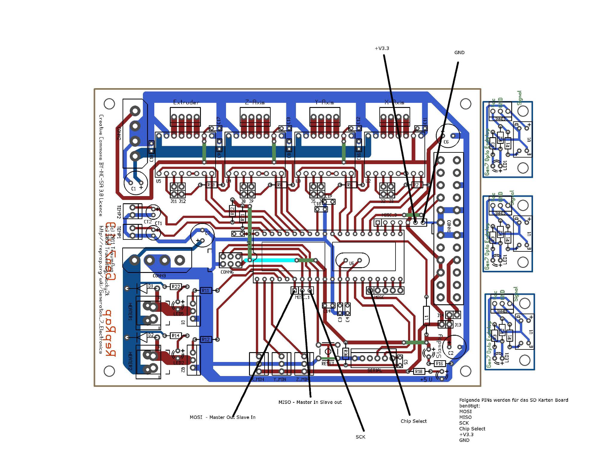
For the SD Card you the following pins:
- Chip Select (define one on your own)
- MOSI (master out slave in from ISP)
- MISO (master in slave out from ISP)
- CLK (from ISP)
For the LCD:
-RS Pin
- Enable Pin
- D4
- D5
- D6
- D7
You have to wire some more pins on your LCD Display correctly (ie: contrast, R/W -> GND)
For a rotary encoder:
- BTN_EN1
- BTN_EN2
- BTN_EN3
One major thing you've forgotten is breaking out some headers for power supply. Take a look at [github.com]. He has also broken out a 3.3V connection so you could power your sd-card directly.
By the way. There is a pull request in Marlin which enables serial LCD Support. You would have to etch an additional board i.e: this one: [www.sparkfun.com] to controll the lcd but it only needs one pin on your ATMEGA1284 for communication with the serial backpack.So you'll have enough pins left for other additional features like a second extruder.
The backpack is Arduino compatible so you could easily extend the firmware on the backpack for controlling additional leds, beeper or whatever.
|
Re: lcd and sd card how many pins needed would it work with an 1284P & marlin March 13, 2012 03:24PM |
Registered: 12 years ago Posts: 279 |
Have a question about that serial interface LCD you know if that interface would be able to handle a bigger like 4x20 lcd?
Also isn't there a limit to what interfaces you can have I mean doesn't the sd card thingy use a serial interface and doesn't the lcd connected this way as well? what would then happen to the computer connection if all the serial are taken?
Power is easy to deal with take 5 v and use a voltage controller and your in business. right? Or if powered by atx you could use a wire off the 3.3V lines from the power supply.
anyways I could use some more ideas.
terramir
|
Re: lcd and sd card how many pins needed would it work with an 1284P & marlin March 14, 2012 04:33AM |
Registered: 12 years ago Posts: 290 |
It should be capable for 16x2, 16x4, 20x4 and 20x2 displays. For interfacing the serial LCD backpack there is a nice arduino library called "serlcd" [flipmu.com]. The library subclasses SoftwareSerial.h which is not dependant on a hardware serial pin. You can simply use any free digital i/o pin for interacting with the backpack. The SD CARD uses the hardware SPI Pins(MOSI,MISO,SCK) and one Pin for "chip select". As you know the SPI Pins are also used for the icsp header.
Your "computer connection" isn't touched at all.
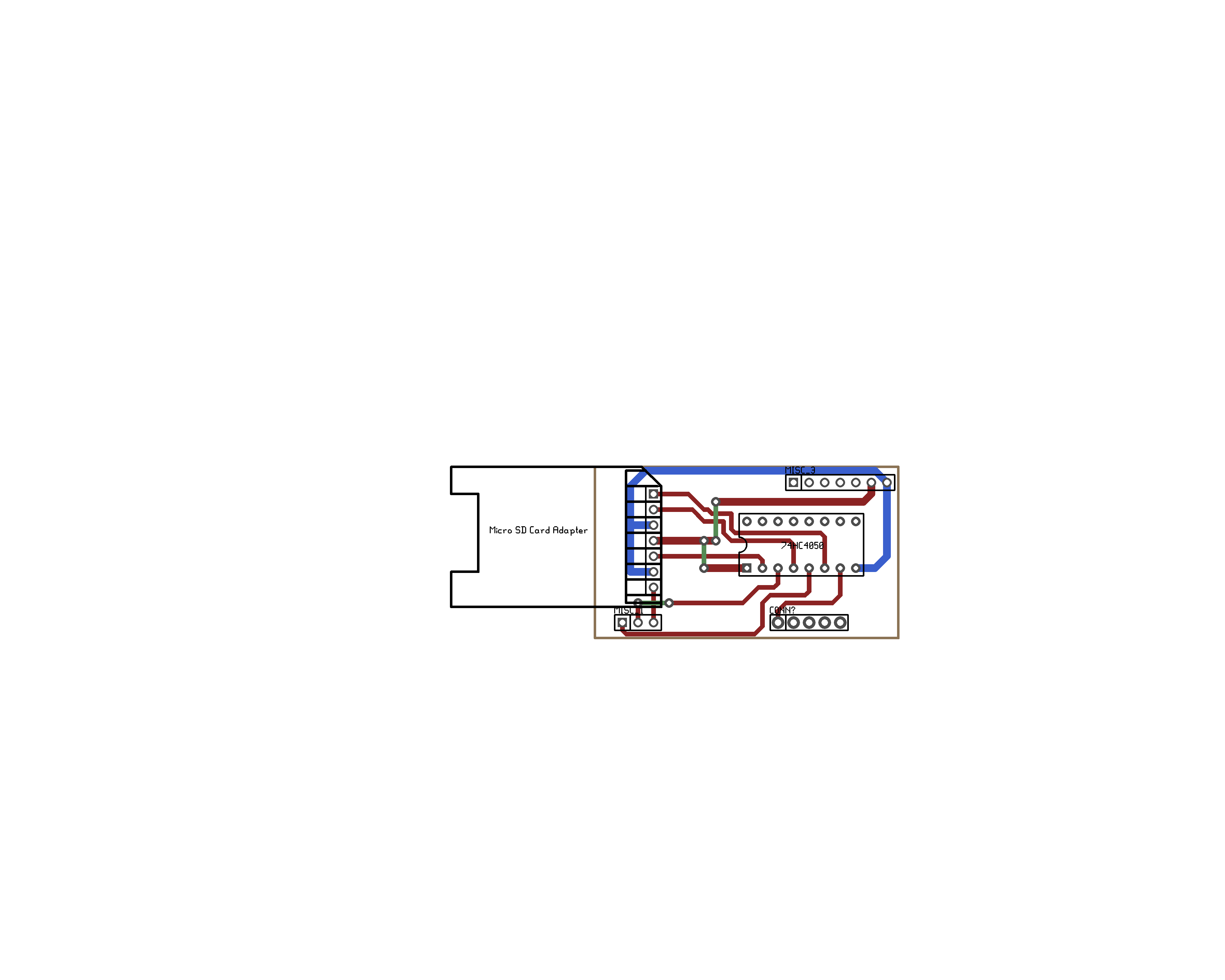
As you said you could use a voltage controller for getting the 3.3V for your the sd-card. But breaking out the 3.3V line from your ATX would be much easier and of course cheaper. Don't forget to use a voltage devider to limit your lines MOSI, SCK and CS to 3.3V. My first attempt was a resistor based voltag devider but that didn't work reliable so i switched to a 74HC4050.
I've finished my etching of the mentioned serial backpack yesterday.(It wasn't easy at all with this f*** 0,1mm thick traces) So I hope I could give you a little more input on this tomorrow.
Your "computer connection" isn't touched at all.
As you said you could use a voltage controller for getting the 3.3V for your the sd-card. But breaking out the 3.3V line from your ATX would be much easier and of course cheaper. Don't forget to use a voltage devider to limit your lines MOSI, SCK and CS to 3.3V. My first attempt was a resistor based voltag devider but that didn't work reliable so i switched to a 74HC4050.
I've finished my etching of the mentioned serial backpack yesterday.(It wasn't easy at all with this f*** 0,1mm thick traces) So I hope I could give you a little more input on this tomorrow.
|
Re: lcd and sd card how many pins needed would it work with an 1284P & marlin March 14, 2012 05:07AM |
Registered: 12 years ago Posts: 279 |
0.1mm traces well I usually fatten them up if they won't be in the way if you look at my attached board you'll see what I did  it can be tricky at times to balance pad size vs thickness of the void inbetween but it is doable.
anyways let me know how it goes by friday I should have my atmega1284p . Btw scuba look at my other topic maybe you know a bit about the gen7 would like your input as well
BTW that atmega what is that thing using and does it have some spare pins maybe we could to control a keyboard and would it have enough flash left over to do it, maybe add that to the serial contollers library in that chip I wonder if peeps have done some work with this?
terramir
it can be tricky at times to balance pad size vs thickness of the void inbetween but it is doable.anyways let me know how it goes by friday I should have my atmega1284p . Btw scuba look at my other topic maybe you know a bit about the gen7 would like your input as well
BTW that atmega what is that thing using and does it have some spare pins maybe we could to control a keyboard and would it have enough flash left over to do it, maybe add that to the serial contollers library in that chip I wonder if peeps have done some work with this?
terramir
|
Re: lcd and sd card how many pins needed would it work with an 1284P & marlin March 14, 2012 06:47AM |
Registered: 12 years ago Posts: 290 |
Also with 0,16mm traces it took several attampts to get a useable resolt. By the way it was my first double layer etching so some faults were just homebrewn 
You mean the ATMEGA on the serial backpack right?! It's mentioned to use an ATMega328 but i think thats way overpowerd. I'm going to use an ATMega8 which is pin compatible with the ATMega328 but has only 8kb flash and the price is about 50%. The serial lcd is designed with all spare pins broken out so you have plenty of space to extend board. Using it for controlling a keyboard will not be possible cause you only have an "rx" line to it. So communication back to your GEN7 is not possible without a hack. But you could use the pins for other fancy things: i.e hook up a beeper (and save one Pin on the GEN7), controll several leds (showing heaters on or whateverr) or hook up a smoke detector and led the beeper alarm you in case of a burning printer . In any case you also have to extend the firmware of the serial backpack. You could simply add special commands to it which will performe your wanted action.
I.e: The firmware recognises an recieved "0xFE" as start for a special command and uses the next byte to identify the uniq command.
You mean the ATMEGA on the serial backpack right?! It's mentioned to use an ATMega328 but i think thats way overpowerd. I'm going to use an ATMega8 which is pin compatible with the ATMega328 but has only 8kb flash and the price is about 50%. The serial lcd is designed with all spare pins broken out so you have plenty of space to extend board. Using it for controlling a keyboard will not be possible cause you only have an "rx" line to it. So communication back to your GEN7 is not possible without a hack. But you could use the pins for other fancy things: i.e hook up a beeper (and save one Pin on the GEN7), controll several leds (showing heaters on or whateverr) or hook up a smoke detector and led the beeper alarm you in case of a burning printer
. In any case you also have to extend the firmware of the serial backpack. You could simply add special commands to it which will performe your wanted action. I.e: The firmware recognises an recieved "0xFE" as start for a special command and uses the next byte to identify the uniq command.
|
Re: lcd and sd card how many pins needed would it work with an 1284P & marlin March 14, 2012 12:29PM |
Registered: 12 years ago Posts: 279 |
the atmega 328pu is about $ 2.82 at mouser the 8 is like 20 cents cheaper might wanna go with the 328pu unless your really seeing it for half off somewhere I'm not seeing 
Anyways so would have to rewrite the firmware right? And then it would use 2 pins? Better than the sd cards four pins. Just wondering because hey two pins are better than four. or 6. I wonder if there is a keyboard library that would use a small one like this or even smaller since we only need a few keys hmmmm.
thanks for the info let me know how it's going
terramir
|
Re: lcd and sd card how many pins needed would it work with an 1284P & marlin March 14, 2012 01:31PM |
Registered: 12 years ago Posts: 279 |
hmm looked at his (alfons) board and saw something he neglected to use the pin on top which is an a/d pin that I did breakout I just figured out how to fix mine though I could breakout the 3.3V by soldering it with a wire directly from the 3.3v and use the second ground from the serial header this should fix my 3.3V power problems however then I still need 5v and 12v power in case I need that for some extensions I figure I'll drill some holes from the 5 and 12v power planes to fix this could also do this to ground and just stick a header in there. Anyways let me know about your progress and I'd like to see how you did the sd card reader
post some pics and maybe a schematic or two
terramir
post some pics and maybe a schematic or two
terramir
|
Re: lcd and sd card how many pins needed would it work with an 1284P & marlin March 14, 2012 08:26PM |
Registered: 12 years ago Posts: 279 |
|
Re: lcd and sd card how many pins needed would it work with an 1284P & marlin March 15, 2012 05:16AM |
Registered: 12 years ago Posts: 290 |
The attached board is one of my first sd card-only extension boards. At the moment I'm using a similar design having the sd card board mounted next to the lcd display (connected through multicore cable to the GEN7).
I've got the ATMEGA at a local store for €2,50.. ordering the ATMEGA328 would be about €5-7 incl. shipping for me.
I know that Alfons doesn't use the last a/d pin. So I've changed his design a little bit for my needs (see attachment) .
You could use any hd44780 compatible LCD display in combination with the serial lcd backpack or directly hooked up to the GEN7.
Sure it would be possible to also use the TX from the backpack to send data back to your GEN7 but changing the sd card routines in your firmware would be a major impact.
|
Re: lcd and sd card how many pins needed would it work with an 1284P & marlin March 16, 2012 09:43AM |
Registered: 13 years ago Posts: 7,616 |
Looks good, scuba, getting 3.3V onto the extension board is an excellent idea.
Is there enough physical space between the ATX24 and your extension header? These connectors have a snapper there.
Also I reviewed how thermistors are fed with GND and 5V according to this: [reprap.org] . v1.3.1 is already a lot better than v1.2, but I think this can be improved further:
I've just uploaded this to Github, it's in the last two commits.
Is there enough physical space between the ATX24 and your extension header? These connectors have a snapper there.
Also I reviewed how thermistors are fed with GND and 5V according to this: [reprap.org] . v1.3.1 is already a lot better than v1.2, but I think this can be improved further:

I've just uploaded this to Github, it's in the last two commits.
| Generation 7 Electronics | Teacup Firmware | RepRap DIY |
|
Re: lcd and sd card how many pins needed would it work with an 1284P & marlin March 16, 2012 12:21PM |
Admin Registered: 17 years ago Posts: 7,879 |
You might consider using a logic drive MOSFET or boosting the gate voltage to 12V like I did here: [hydraraptor.blogspot.com]. Small signal FETs only cost pennies.
5V isn't enough gate drive for a MOSFET with a gate threshold of 4V. The threshold is where it just starts to conduct and pass 0.25ma. This is particularly true for boards that get their power from USB, as it is often only about 4.7V. (USB power is intended for driving 3.3V devices with an LDO regulator, it isn't meant to power 5V devices).
I suspect this is why some people's MOSFETs fry, whereas others get away with it.
[www.hydraraptor.blogspot.com]
|
Re: lcd and sd card how many pins needed would it work with an 1284P & marlin March 16, 2012 01:55PM |
Registered: 13 years ago Posts: 7,616 |
Thanks for the opinion, nophead. Actually I've read and heard a lot of different opinions about these MOSFETS, so finally I've run a measurement series: [reprap.org]
Do you think this can become substantially better, justifying another piece of electronics?
Do you think this can become substantially better, justifying another piece of electronics?
| Generation 7 Electronics | Teacup Firmware | RepRap DIY |
|
Re: lcd and sd card how many pins needed would it work with an 1284P & marlin March 16, 2012 03:01PM |
Registered: 12 years ago Posts: 290 |
Thanks Traumflug! But the that was not my idea... it like this was taken from "Alfons3"s design. Actually there is a little space conflict with the snapper of the ATX connector. In my case i've just cut it off. Great to see that the thermistor pins have moved one to the left. My aproach of breaking out the upper left AI0 a/d pin is nothing but a temporary solution.
|
Re: lcd and sd card how many pins needed would it work with an 1284P & marlin March 16, 2012 03:03PM |
Admin Registered: 17 years ago Posts: 7,879 |
I think all MOSFETs will run cooler, those with thresholds towards the top of the range (that current fry) will work, and the maximum bed temperature will be higher. Not bad for an extra transistor and two resistors. It can be done with one resistor less but it would need a firmware change.
You only tested a single MOSFET on a single power supply. If you look at the datasheet you will see the threshold can vary between 2 and 4V. Electronic design is not an empirical process. If you want to drive direct from logic then use a logic drive FET, otherwise boost the voltage. Boosting the voltage is generally the cheaper option when you are not short of board space.
[www.hydraraptor.blogspot.com]
|
Re: lcd and sd card how many pins needed would it work with an 1284P & marlin April 11, 2012 08:00AM |
Registered: 12 years ago Posts: 7 |
Hi
I am interested in building one of these with the SD card so it can run the G Code without using a PC.
Is that possible with the current Gen7 software/hardware?
If not - is it in the pipeline?
I would like to do my own board in surface mount as I can get boards made in China for around $1.50 each (100 off) double sided plated through hole with silk screen.
I would be happy to offer these at cost (plus shipping) if there is interest in this.
Regards
Denis
|
Re: lcd and sd card how many pins needed would it work with an 1284P & marlin April 11, 2012 12:19PM |
Registered: 13 years ago Posts: 7,616 |
Quote
Is that possible with the current Gen7 software/hardware?
To some extents. You have to reconfigure your firmware to only use endstops which do not also share their ATmega pin with the ICMP header. Then fit Kliment's SD card holder and wire the card select pin with a piece of isolated wire.
Quote
If not - is it in the pipeline?
Yes: [forums.reprap.org]
| Generation 7 Electronics | Teacup Firmware | RepRap DIY |
Sorry, only registered users may post in this forum.