Generation 7 LCD + SD pinouts
Posted by peter6960
|
Generation 7 LCD + SD pinouts October 07, 2012 06:24AM |
Registered: 11 years ago Posts: 121 |
Hi
I have some free time this week and want to make up a expansion header for Gen 7 1.4.1 and newer with supporting circuitry for LCD and SD card
This will be for use with Marlin
Can anyone give me the correct pinouts from Gen7Expansion header to LCD/Encoder? Schametic perhaps?
Of if that has been done, point me to it as a search here and google didn't deliver anything.
Peter
|
Re: Generation 7 LCD + SD pinouts October 08, 2012 06:28AM |
Registered: 13 years ago Posts: 7,616 |
It's in Gen7's repository, obviously. The footprint for the header also serves as a footprint for the plug-in board. As you sound like someone who doesn't have gEDA, here's a picture:

| Generation 7 Electronics | Teacup Firmware | RepRap DIY |
|
Re: Generation 7 LCD + SD pinouts October 08, 2012 08:49AM |
Registered: 11 years ago Posts: 121 |
"header to LCD/Encoder"...
I have seen the actual header yes, but this being first try at putting sd/lcd in it, I was hoping for a "what goes where"
Yes I know I could read and experiment, but was hoping someone here has done similar already
PS: I do have gEDA (and Kicad and Eagle...) (;
Peter
I have seen the actual header yes, but this being first try at putting sd/lcd in it, I was hoping for a "what goes where"
Yes I know I could read and experiment, but was hoping someone here has done similar already
PS: I do have gEDA (and Kicad and Eagle...) (;
Peter
|
Re: Generation 7 LCD + SD pinouts October 08, 2012 01:59PM |
Registered: 11 years ago Posts: 273 |
Hello,
I am also planning to use the GEN7 1.4.1 expansion header to connect SD-Card, Display, Rotary Encoder.
Also in the future I might like to connect a FAN and maybe even a second extruder. So my plans are currently to use the following PIN assignment, as the Display is going to be connected by I2C:
* 5 MOSI
* 6 MISO
* 7 SCK
* 10
* 11
* 12 SDSS
* 13 FAN
* 14 EXT1_HEAT PWM
* 22 SCL
* 23 SDA
* 24 AI7 EXT1_TEMP
* 26 EXT_1_STEP
* 27 EXT_1_DIR
* SD_CARD 5,6,7,12
* UserInterface 22,23 alternative rotary key 10,11
* 2. Extruder 14,24,26,27
Any suggestion or issues with these assignments ?
So for the SD-Card MISO,MOSI and SCK are required. You need an additional PIN for SS (select). For a LCD you need at least 4 Data, RS, Enable (making 6 outputs). Directly connected 10 of 13 free Pins, so you could get it working directy. But I2C or a 74HCT595 (shift-register) will give you some additional ports for FAN, 2nd Extruder.
I tried to not assign the A7 as this is the only analog port on the expansion header for the temperature measurement of an additional extruder. For the rotary encoder it might be useful to have interrupt pins. I2C only needs SCL and SDA afaik. You can get a cheap PCF8574 connected on SCL,SDA to get extra 8 ports.
cu
Michael
Edited 1 time(s). Last edit at 10/08/2012 02:21PM by mcp.
|
Re: Generation 7 LCD + SD pinouts October 08, 2012 02:42PM |
Registered: 11 years ago Posts: 121 |
|
Re: Generation 7 LCD + SD pinouts October 08, 2012 05:30PM |
Registered: 13 years ago Posts: 7,616 |
Me agree? What for? I have no idea how a display is connected to an ATmega.
But I do have a schematics for a SD card ExtensionBoard, along with an layout excerpt to show which connector goes where. It's a design done by Alfons3 somewhere between v1.3 and v1.4 and matches that of Gen3 electronics.:
That said, I'm pretty sure Kliment's SD Card adapter works, too. You'd just have to solder a wire for the card select signal.
Actually, the reasons why there is no SD Card ExtensionBoard is, I can't find a reasonably priced card holder and many other things related to Gen7, like enhancing gEDA, enhancing Visolate, teaching Teacup a proper look-ahead, building a RepRap machine really suitable for PCB milling ( <-- most important right now) and all this pains me in my ... back more.
But I do have a schematics for a SD card ExtensionBoard, along with an layout excerpt to show which connector goes where. It's a design done by Alfons3 somewhere between v1.3 and v1.4 and matches that of Gen3 electronics.:


That said, I'm pretty sure Kliment's SD Card adapter works, too. You'd just have to solder a wire for the card select signal.
Actually, the reasons why there is no SD Card ExtensionBoard is, I can't find a reasonably priced card holder and many other things related to Gen7, like enhancing gEDA, enhancing Visolate, teaching Teacup a proper look-ahead, building a RepRap machine really suitable for PCB milling ( <-- most important right now) and all this pains me in my ... back more.
| Generation 7 Electronics | Teacup Firmware | RepRap DIY |
|
Re: Generation 7 LCD + SD pinouts October 08, 2012 06:18PM |
Registered: 11 years ago Posts: 121 |
Thanks sir... I did notice Alfons3 mentioned he stopped development because the resistors werent working reliably... Will agree though that we use the same pins, but I'll do one with a CD4050 to do level shifting instead... Will report how it goes.
That pinout is much appreciated.
MCP, when do you plan on starting to do the LCD?
What firmware are you running? (or plan to - as Teacup has no LCD)
That pinout is much appreciated.
MCP, when do you plan on starting to do the LCD?
What firmware are you running? (or plan to - as Teacup has no LCD)
|
Re: Generation 7 LCD + SD pinouts October 09, 2012 02:28AM |
Registered: 11 years ago Posts: 273 |
Hello,
I will start Display, SD_Card and Keys as soon as I get my printer printing. I use repetier as it contains already SD_Card, Display and Keys.
For the SD_Card I will use an arduino SD_Card adapter from ebay (Also resistore based) to start with.
@Traumflug, at least these adapters are quite cheap, < 2$....
cu
Michael
|
Re: Generation 7 LCD + SD pinouts October 09, 2012 03:52AM |
Registered: 11 years ago Posts: 121 |
|
Re: Generation 7 LCD + SD pinouts October 09, 2012 04:20AM |
Registered: 11 years ago Posts: 273 |
|
Re: Generation 7 LCD + SD pinouts October 09, 2012 04:24AM |
Registered: 11 years ago Posts: 121 |
|
Re: Generation 7 LCD + SD pinouts October 09, 2012 05:46AM |
Registered: 13 years ago Posts: 7,616 |
Quote
as Teacup has no LCD
Shouldn't be too difficult to put this in.
| Generation 7 Electronics | Teacup Firmware | RepRap DIY |
|
Re: Generation 7 LCD + SD pinouts October 09, 2012 06:05AM |
Registered: 11 years ago Posts: 121 |
|
Re: Generation 7 LCD + SD pinouts October 09, 2012 03:13PM |
Registered: 11 years ago Posts: 273 |
Hello,
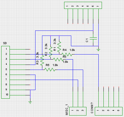
I'd liko to go for 2 PCB, one on the extension ports and one for the Display, SD-Card and Encoder.
Both connected by a 10 pin Wire.
See the attached schematic for the adapter. I will try to do the Display Key later.
For the display and encoder the schematic would look something like this.
cu
Michael
Edited 1 time(s). Last edit at 10/09/2012 03:56PM by mcp.
I'd liko to go for 2 PCB, one on the extension ports and one for the Display, SD-Card and Encoder.
Both connected by a 10 pin Wire.
See the attached schematic for the adapter. I will try to do the Display Key later.

For the display and encoder the schematic would look something like this.

cu
Michael
Edited 1 time(s). Last edit at 10/09/2012 03:56PM by mcp.
|
Re: Generation 7 LCD + SD pinouts October 10, 2012 05:53AM |
Registered: 12 years ago Posts: 290 |
I can confirm that Afons3 resistor based variant isn't working properly. I'm using a 74HC4050 for voltage dropping.
As Traumflug said it's hard to find an inexpensive sd card holder. So I'm using a simple Micro SD Adapter for 1€.
At the moment im running Marlin on my Gen7 1.4 together with an SD Card/LCD/Rotary Encoder.
But I'm experiencing connection issues midprint. LCD Display sometimes blanks out and from time to time there are problems while printing from SD Card. I think I should add a ferrit core to my connector cables ;-)
peter6960 Wrote:
-------------------------------------------------------
> Thanks sir... I did notice Alfons3 mentioned he
> stopped development because the resistors werent
> working reliably... Will agree though that we use
> the same pins, but I'll do one with a CD4050 to do
> level shifting instead... Will report how it
> goes.
>
> That pinout is much appreciated.
>
> MCP, when do you plan on starting to do the LCD?
>
> What firmware are you running? (or plan to - as
> Teacup has no LCD)
|
Re: Generation 7 LCD + SD pinouts October 10, 2012 07:07AM |
Registered: 13 years ago Posts: 7,616 |
Quote
peter6960
will come back to Teacup once it does
This way it'll never get it, because you're the only one who could test such stuff.
 No problem, though.
Quote
scuba
I can confirm that Afons3 resistor based variant isn't working properly.
Do you have an idea what's going wrong there? Using resistor dividers is a recommended strategy in some FAQs. Another chip-less level conversion strategy is this one, taken from [vusb.wikidot.com] . 3.3V signals to the left, 5V signals to the right:

| Generation 7 Electronics | Teacup Firmware | RepRap DIY |
|
Re: Generation 7 LCD + SD pinouts October 11, 2012 07:47AM |
Registered: 12 years ago Posts: 290 |
Sorry Traumflug... my electronic knowledge is only self educated  . I've also come around some FAQs and Posts in arduino forums which mention this methode. So I've broadboarded one of those some months ago.
Most of the time the firmware faild to initiate the SdCard... if that worked it couldn't read the filesystem and so on...
About 1 of 20 tries the sdcard got read correctly but that didn't satisfy me.
I think i can remeber that someone told me that a resistor based level devider doesn't "switch" fast enough. But I can't tell if that's technical correct
. I've also come around some FAQs and Posts in arduino forums which mention this methode. So I've broadboarded one of those some months ago. Most of the time the firmware faild to initiate the SdCard... if that worked it couldn't read the filesystem and so on...
About 1 of 20 tries the sdcard got read correctly but that didn't satisfy me.
I think i can remeber that someone told me that a resistor based level devider doesn't "switch" fast enough. But I can't tell if that's technical correct
|
Re: Generation 7 LCD + SD pinouts October 11, 2012 02:44PM |
Registered: 13 years ago Posts: 7,616 |
Quote
a resistor based level devider doesn't "switch" fast enough.
Quite possible and depends on the resistor values choosen (again, that's what I've read in some FAQ).
Imagine each of the pins is connected with a capacitor. So, to get this cap to a given voltage, this cap has to be filled, requiring a current to flow for some time. The lower the current, the longer it takes to fill this cap and the longer it takes to make the pin recognize the signal. All that happens in the nanoseconds range.
A solution would be to either reduce the communications speed with the SD card or to make these resistors smaller, e.g. half the value for each of them. Smaller resistors give more current to the pin, but also waste more current out of the sending pin (which isn't always neglibile).
Didn't want to disturb your work, just share a bit of what I've found out.
| Generation 7 Electronics | Teacup Firmware | RepRap DIY |
|
Re: Generation 7 LCD + SD pinouts October 12, 2012 04:16AM |
Registered: 12 years ago Posts: 290 |
|
Re: Generation 7 LCD + SD pinouts October 12, 2012 06:46AM |
Registered: 11 years ago Posts: 121 |
Agreed. CD4050 locally cost almost as much as having to buy the minimum quantity of resistors (100 packs only) so that's what I'll be going with
Bought a 20x4 LCD, PCF8574, Encoder etc
Thus far, here's a stripboard version. Havent tested the i2c yet....
Also encoder not wired up yet
So plan:
1. Test i2c LCD
2. Test i2c encoder - if that doesnt work wire encoder directly.
att CD4050 and SD Breakout onto the stripboard, and test full print from SD, menu etc
Peter


|
Re: Generation 7 LCD + SD pinouts October 12, 2012 08:20AM |
Registered: 13 years ago Posts: 387 |
Hi Peter, that looks very promising, almost the same thing I thought about yesterday, but you soldered a bit faster. 
How did you assign the LCD pins to the PCF8574 and why do you think that the encoder wouldn´t work over I2C?
There are only 10 types of people in the world —
those who understand binary, and those who don't.
GSG-Elektronik
How did you assign the LCD pins to the PCF8574 and why do you think that the encoder wouldn´t work over I2C?
There are only 10 types of people in the world —
those who understand binary, and those who don't.
GSG-Elektronik
|
Re: Generation 7 LCD + SD pinouts October 12, 2012 08:23AM |
Registered: 11 years ago Posts: 121 |
I wired the above as per MCP's schematic.
The only Arduino i2c library I could find, uses a different order for the pins from PCF8574 to the LCD.
Can you help me with a sketch/library to test this with?
PCF8574 -> LCD
Pin 5 = D8
Pin 6 = D7
Pin 7 = D6
Pin 9 = D5
Pin 11 = E
Pin 12 = RS
and did you verify your schematic against how Repetier should be?
mcp Wrote:
-------------------------------------------------------
> Hello,
> I'd liko to go for 2 PCB, one on the extension
> ports and one for the Display, SD-Card and
> Encoder.
>
> Both connected by a 10 pin Wire.
>
> See the attached schematic for the adapter. I will
> try to do the Display Key later.
>
>
> For the display and encoder the schematic would
> look something like this.
>
>
> cu
>
> Michael
|
Re: Generation 7 LCD + SD pinouts October 12, 2012 08:31AM |
Registered: 11 years ago Posts: 121 |
Chopper925 Wrote:
> why do you think that the encoder wouldn´t work over I2C?
I quote from the following page: [www.repetier.com]
"If you have the pins, use direct connection. It is much faster and less error prone. A rotary encoder over I2C works only with slow turns!"
It's under the "User interface configuration" section just past halway through the page.
Peter
|
Re: Generation 7 LCD + SD pinouts October 12, 2012 09:18AM |
Registered: 11 years ago Posts: 121 |
Got i2c LCD tested:
Library:
[www.sainsmart.com]
Sketch below matches pins above
Edited 3 time(s). Last edit at 10/12/2012 09:31AM by peter6960.
Library:
[www.sainsmart.com]
Sketch below matches pins above
/*
** Address pins 0,1 & 2 are all permenantly tied high so the address is fixed at 0x27
** However if you have a PCF8574A (the +A bit) base address starts at 0x38
**
** Written for and tested with Arduino 1.0
** This example uses F Malpartida's NewLiquidCrystal library. Obtain from:
** [bitbucket.org]
**

#include Wire.h
#include LCD.h
#include LiquidCrystal_I2C.h

#define I2C_ADDR    0x38  // Define I2C Address where the PCF8574A is
#define En_pin  6
#define Rw_pin  0
#define Rs_pin  7
#define D4_pin  4
#define D5_pin  3
#define D6_pin  2
#define D7_pin  1

int n = 1;

LiquidCrystal_I2C	lcd(I2C_ADDR,En_pin,Rw_pin,Rs_pin,D4_pin,D5_pin,D6_pin,D7_pin);

void setup()
{
  lcd.begin(20,4);

// Switch on the backlight
  lcd.home();                   // go home

 lcd.print("I2C tester");
  lcd.setCursor ( 0, 1 );        // go to the 2nd line
  lcd.print("F Malpartida library");
  lcd.setCursor ( 0, 2 );        // go to the third line
  lcd.print("Test By OpenHardware");
  lcd.setCursor ( 0, 3 );        // go to the fourth line
  lcd.print(".co.za ");}

void loop()
{
  // Backlight on/off every 3 seconds
  lcd.setCursor(14,3);        // go col 14 of line 3
  lcd.print(n++,DEC);
}

Edited 3 time(s). Last edit at 10/12/2012 09:31AM by peter6960.
|
Re: Generation 7 LCD + SD pinouts October 12, 2012 09:41AM |
Registered: 11 years ago Posts: 273 |
|
Re: Generation 7 LCD + SD pinouts October 12, 2012 09:46AM |
Registered: 11 years ago Posts: 273 |
Hello Peter,
congratulations, seems to work fine, so just repetier on the GEN7 and it should work. Make sure you set the PIN for the FAN so it does not conflict with the temerature sensors. Not sure if this was adjusted. Set FAN to -1 ;-)
Took me 1 week to figure out what was the reason for my bead to stay at 470 C ;-(
cu
Michael
|
Re: Generation 7 LCD + SD pinouts October 12, 2012 09:56AM |
Registered: 11 years ago Posts: 121 |
Ahhhh! I luckily don't have a bed on mine, but you can't believe how thats been driving me up the wall. I'll make a seperate thread in the firmware thread later - but here's the issues I have with Repetier - perhaps you had some too?
Note the below all works in Teacup just perfectly:
1. Bed temp at 500 degree - fixed now
2. Endstops trigger randomly before axis is homed - even though internal pullups is set (same as teacup also set)
3. Missed steps - only in X axis - when back on teacup not an issue. Have bought a new pololu too before going back to teacup and finding old driver to be fine.
So next step, the encoder.
I have these: [www.netram.co.za]
I have never used a rotary encoder before and spent the last few minutes looking for a PCF8574 schematic with a photo to check pins. Any help?
Peter
|
Re: Generation 7 LCD + SD pinouts October 12, 2012 11:56AM |
Registered: 11 years ago Posts: 121 |

|
Re: Generation 7 LCD + SD pinouts October 12, 2012 12:03PM |
Registered: 11 years ago Posts: 121 |
This will be how to set it in Reperier's uiconfig.h then...
Define the pin
*/
#if UI_DISPLAY_TYPE==3 // I2C Pin configuration
#define UI_DISPLAY_RS_PIN _BV(7)
#define UI_DISPLAY_RW_PIN _BV(0)
#define UI_DISPLAY_ENABLE_PIN _BV(6)
#define UI_DISPLAY_D0_PIN _BV(0)
#define UI_DISPLAY_D1_PIN _BV(1)
#define UI_DISPLAY_D2_PIN _BV(2)
#define UI_DISPLAY_D3_PIN _BV(3)
#define UI_DISPLAY_D4_PIN _BV(4)
#define UI_DISPLAY_D5_PIN _BV(3)
#define UI_DISPLAY_D6_PIN _BV(2)
#define UI_DISPLAY_D7_PIN _BV(1)
|
Re: Generation 7 LCD + SD pinouts October 12, 2012 12:20PM |
Registered: 11 years ago Posts: 121 |
MCP, I don't understand you're schematic... Why the second PCF8547, just for one button? Though I do like that you have the rotary encoder directly wired (faster). Or do you plan to add a Back button and any other buttons or LEDs?
Same arduino sketch above, works perfectly on the Gen7 board, however, cannot get Repetier to initialise the display
Peter
Posted it here in Firmware [forums.reprap.org]
Peter
Edit: Saturday:
Repetier himself helped me sort out the issue: I2C address was wrong, should be 0x70 in his libraries.
So one of 3 goals can be checked off. Next encoder + buttons, then SD
mcp Wrote:
-------------------------------------------------------
> Hello,
> I'd liko to go for 2 PCB, one on the extension
> ports and one for the Display, SD-Card and
> Encoder.
>
> Both connected by a 10 pin Wire.
>
> See the attached schematic for the adapter. I will
> try to do the Display Key later.
>
>
> For the display and encoder the schematic would
> look something like this.
>
>
> cu
>
> Michael
Edited 2 time(s). Last edit at 10/13/2012 05:54AM by peter6960.
Same arduino sketch above, works perfectly on the Gen7 board, however, cannot get Repetier to initialise the display
Peter
Posted it here in Firmware [forums.reprap.org]
Peter
Edit: Saturday:
Repetier himself helped me sort out the issue: I2C address was wrong, should be 0x70 in his libraries.


So one of 3 goals can be checked off. Next encoder + buttons, then SD
mcp Wrote:
-------------------------------------------------------
> Hello,
> I'd liko to go for 2 PCB, one on the extension
> ports and one for the Display, SD-Card and
> Encoder.
>
> Both connected by a 10 pin Wire.
>
> See the attached schematic for the adapter. I will
> try to do the Display Key later.
>
>
> For the display and encoder the schematic would
> look something like this.
>
>
> cu
>
> Michael
Edited 2 time(s). Last edit at 10/13/2012 05:54AM by peter6960.

Sorry, only registered users may post in this forum.