Generation 7 Electronics Development
Posted by Traumflug
|
Re: Generation 7 Electronics Development January 30, 2012 05:14AM |
Registered: 14 years ago Posts: 3,742 |
The PCB heat bed requires 10 A, this will burn out any normal MOSFET!
Bob Morrison
Wörth am Rhein, Germany
"Luke, use the source!"
BLOG - PHOTOS - Thingiverse
Bob Morrison
Wörth am Rhein, Germany
"Luke, use the source!"
BLOG - PHOTOS - Thingiverse
|
Re: Generation 7 Electronics Development January 30, 2012 06:52AM |
Registered: 13 years ago Posts: 7,616 |
Quote
this will burn out any normal MOSFET!
Depends on what you consider to be a "normal" MOSFET. There are definitely ones which can handle 10A, the IRFZ44N is specified for 49 amps at 25°C and 35 amps at 100°C.
One always learns new things. There are over 100 Gen7s out there, all of them apparently working well so far. The problem with a relay is, a relay can't do PWM in the multi-kHz range.
It's right, PWM heats up the MOSFET more than occasional switching. One solution could be to reduce the PWM frequency, which currently defaults to the maximum of 65 kHz in Teacup. This can be divided by 2, 4, 8, 16 easily. Some people fear going into the audible range makes the MOSFET switching hearable. I didn't test this so far.
Another solution could be - as suggested - to get rid of PWM at all. Just on/off.
Both solutions require to change Teacup firmware, I don't know what other firmwares (FiveD, Repetier) are doing.
Phil, I'll make sure to send out replacements today. Actually, I've already bought two alternatives for the IRFZ44N, both more expensive, and 10 Ohms resistors to replace the 1kOhms ones (faster filling of the gate). I meant to search for a better solution when developing the current design, but as everything apparently worked well, I forgot about that.
| Generation 7 Electronics | Teacup Firmware | RepRap DIY |
|
Re: Generation 7 Electronics Development January 30, 2012 02:26PM |
Registered: 12 years ago Posts: 44 |
Traumflug Wrote:
I expect it could be divided by 256 (or 1024) easily, too. Though I didn't test this so far, either. Also, I guess some beds may begin to sing if they get into the audible range. I can't imagine they will sing as loud as the steppers, though.
Yes, so I thought I would try bang-bang on a relay. But after reading more, I agree that PID control would be preferable.
Oh, yeah! Faster/lower resistor makes sense, now that you mention it. I had thought maybe the resistance was too low and resulting in too much gate-current, so I checked the schematic and saw it was 1k. I didn't think about the resulting switching time delay. Nice idea.
But I didn't expect you send me replacements. I only wanted to find a good explanation. But, wow! Thanks very much. I'll let you know how the new one works out.
I'm thinking I might need to move the real power-MOSFET onto the bed itself and drive that from the Gen7 MOSFET or just with the AVR output pin directly. Do you have an suggestions on this path?
I'm a software guy and I tend to confuse electronics with my digital thinking. But I think something like this would help:
Then I can dump the waste heat from the actual power MOSFET into the bed. So long as my bed temperature is below the MOSFET's Tmax, I think I'll be ok, except maybe for some uneven heating.
Another idea is to replace the bed MOSFET with a Thyristor and drive the bed with 110VAC. But this will not easily mesh with the PID control, afaik. Also, I would need to add a lot more safety cages to my bed. But since It's taking me 12-15 minutes to reach 100C using direct 12V inputs (bypassing the Gen7), I probably need to step up to 30VDC or go all the way to mains voltage.
USD$40 for the PCB heatbed is starting to look like a bargain.
Phil
Quote
Traumflug
It's right, PWM heats up the MOSFET more than occasional switching. One solution could be to reduce the PWM frequency, which currently defaults to the maximum of 65 kHz in Teacup. This can be divided by 2, 4, 8, 16 easily. Some people fear going into the audible range makes the MOSFET switching hearable. I didn't test this so far.
I expect it could be divided by 256 (or 1024) easily, too. Though I didn't test this so far, either. Also, I guess some beds may begin to sing if they get into the audible range. I can't imagine they will sing as loud as the steppers, though.
Quote
Traumflug
Another solution could be - as suggested - to get rid of PWM at all. Just on/off.
Yes, so I thought I would try bang-bang on a relay. But after reading more, I agree that PID control would be preferable.
Quote
Traumflug
Phil, I'll make sure to send out replacements today. Actually, I've already bought two alternatives for the IRFZ44N, both more expensive, and 10 Ohms resistors to replace the 1kOhms ones (faster filling of the gate).
Oh, yeah! Faster/lower resistor makes sense, now that you mention it. I had thought maybe the resistance was too low and resulting in too much gate-current, so I checked the schematic and saw it was 1k. I didn't think about the resulting switching time delay. Nice idea.
But I didn't expect you send me replacements. I only wanted to find a good explanation. But, wow! Thanks very much. I'll let you know how the new one works out.
Quote
Traumflug
I meant to search for a better solution when developing the current design, but as everything apparently worked well, I forgot about that.
I'm thinking I might need to move the real power-MOSFET onto the bed itself and drive that from the Gen7 MOSFET or just with the AVR output pin directly. Do you have an suggestions on this path?
I'm a software guy and I tend to confuse electronics with my digital thinking. But I think something like this would help:
----------------------Gen7 electronics---+       +----- Heated bed-------------------------------
                                         |       |
[AVR]----[10R]----[gate MOSFET drain]----| ~ ~ ~ |---[10R]---[gate  MOSFET  drain]---[heater]--+
                        source           |       |                  source                     |
                           |             |       |                     |                       |
[ GND ]--------------------+-------------| ~ ~ ~ |---------------------+                       |
[v=12V]----------------------------------| ~ ~ ~ |---------------------------------------------+
                                         |       |
----------------------Gen7 electronics---+       +----- Heated bed-------------------------------
Then I can dump the waste heat from the actual power MOSFET into the bed. So long as my bed temperature is below the MOSFET's Tmax, I think I'll be ok, except maybe for some uneven heating.
Another idea is to replace the bed MOSFET with a Thyristor and drive the bed with 110VAC. But this will not easily mesh with the PID control, afaik. Also, I would need to add a lot more safety cages to my bed. But since It's taking me 12-15 minutes to reach 100C using direct 12V inputs (bypassing the Gen7), I probably need to step up to 30VDC or go all the way to mains voltage.
USD$40 for the PCB heatbed is starting to look like a bargain.
Phil
|
Re: Generation 7 Electronics Development January 31, 2012 06:15AM |
Registered: 13 years ago Posts: 7,616 |
So, a few MOSFETs are shipping since yesterday.
Your idea of moving the MOSFET to the heated bed is a good one. I don't see a need for double MOSFETs, though. If you want to try, the pins on the MISC header are free and some of them are PWM-able.
To get on/off behaviour, you can turn on BANG_BANG in Teacup's config.h and set BANG_BANG_ON to 255 and BANG_BANG_OFF to 0.
Ideally, one would do a bit research and first try to find out at which PWM ratio the MOSFET heats up most. Likely, this is neither 0 nor 255, but somewhere between 128 and 200. Then change one piece in the equitation and look again - how hot it gets at a steady usage, like 20 minutes.
I've attached my own config.h which is configured to drive a DC motor spindle instead of a temperature controlled heater. There you can set PWM to constant values with M104 S0 (off) ... M104 S128 (half open) ... M104 S255 (full open).
| Generation 7 Electronics | Teacup Firmware | RepRap DIY |
|
Re: Generation 7 Electronics Development January 31, 2012 10:33AM |
Registered: 12 years ago Posts: 44 |
Quote
Traumflug
To get on/off behaviour, you can turn on BANG_BANG in Teacup's config.h and set BANG_BANG_ON to 255 and BANG_BANG_OFF to 0.
I tried this but I didn't think I needed to change the ON/OFF values from their "defaults"; I thought they were hysteresis marks (inputs), but now I see they might be the ON and OFF output values. I'll give it a shot later to see if it helps.
Quote
Traumflug
Ideally, one would do a bit research and first try to find out at which PWM ratio the MOSFET heats up most. Likely, this is neither 0 nor 255, but somewhere between 128 and 200. Then change one piece in the equitation and look again - how hot it gets at a steady usage, like 20 minutes.
I did some research. I added the RepetierHost "M203" extension for PID/Temperature graphing so I could see the PID values relative to bed temperature rise. I didn't see much PWM at all, really; it spent most of its time at 255 or at 0. But I didn't measure the temperature of the MOSFET at the same time. Clearly it goes from DAMN-HOT to REALLY-DAMN-HOT at some point, but to me they both seem the same.
|
Re: Generation 7 Electronics Development January 31, 2012 02:00PM |
Registered: 13 years ago Posts: 7,616 |
True. Instead of researching and fixing the electronics you can also try to "fix" the PID algorithm and hope the algorithm never reaches the area blowing the MOSFET, of course.
| Generation 7 Electronics | Teacup Firmware | RepRap DIY |
|
Re: Generation 7 Electronics Development February 16, 2012 09:25AM |
Registered: 12 years ago Posts: 44 |
Update: I ordered some IRF2804 MOSFETS from Mouser before you sent me new ones as well. I think the specs are similar to the IRF3803 you gave me, but maybe a little more generous.
My temporary VCR-motor-controller-switch (some NEC transistor) was working without overheating, but I also had a huge heatsink and a fan on it. Also it limited my bed current so that my temp only reached about 70C.
I made room to mount the MOSFET directly to the bed, but at the last minute I decided to try it once more on the Gen7 board directly. It works great. It's not overheating. It is not even noticeably warm when I leave the fan turned off, though I haven't tried this up in the PID region.
Also, I did some more PID analysis on RepetierHost and I can see that, for the bed anyway, the PID is acting almost like BANG-BANG. It needs some tuning for my specific layout, maybe. It cycles back and forth between 0 and 255 with a few intermediate values while the temperature swings about 3 degrees north and south of my target temperature (130C).
|
Re: Generation 7 Electronics Development February 16, 2012 05:25PM |
Registered: 13 years ago Posts: 7,616 |
Don't expect these PID values to be well calculated or even well tested. Most likely, they are the ones from the first guy who shouted "it works for me!" 
| Generation 7 Electronics | Teacup Firmware | RepRap DIY |
|
Re: Generation 7 Electronics Development February 17, 2012 04:59AM |
Admin Registered: 12 years ago Posts: 2,569 |
The Gen7 I built works like a charm with Teacup, but I have some freezes during prints : printer stop moving, and doesn't reply to host software (printerface) until I reset it.
I suspect some electrical interference, but how to find if they happen on the usb cable or comes from the PSU ?
Most of my technical comments should be correct, but is THIS one ?
Anyway, as a rule of thumb, always double check what people write.
I suspect some electrical interference, but how to find if they happen on the usb cable or comes from the PSU ?
Most of my technical comments should be correct, but is THIS one ?
Anyway, as a rule of thumb, always double check what people write.
|
Re: Generation 7 Electronics Development February 17, 2012 07:21AM |
Registered: 13 years ago Posts: 7,616 |
If the PSU whould have dropouts, the ATmega whould simply reset. It's in the USB/serial area.
If it happens often enough it might be worth trying to find out why serial simply stops working. Likely some race condition which happens rarely for most of us, like once a month.
Another thing I experience from time to time is, the USB of my PC (a very old iBook) simply locks up. Then cycling (unplugging and plugging) the USB cable is required.
| Generation 7 Electronics | Teacup Firmware | RepRap DIY |
|
Re: Generation 7 Electronics Development February 17, 2012 09:59AM |
Admin Registered: 12 years ago Posts: 2,569 |
I wasn't able to complete more than 15 minutes of print before it happens till now. I have tried to lower the baud rate but it doesn't seem to help.
I'll try to find some ferrite-protected usb cable to see if that helps.
I only have access to that machine once a week, so It'll be slow reports here, but I'm willing to try and find what happens. First thing is to test with the ferrite usb cable, then if that still happens what could I do to investigate further ?
Most of my technical comments should be correct, but is THIS one ?
Anyway, as a rule of thumb, always double check what people write.
|
Re: Generation 7 Electronics Development February 17, 2012 04:38PM |
Registered: 14 years ago Posts: 380 |
Considering the very long time constant of a heated bed compared to the hot end of the extruder, a 1hz PWM, which is basically a bang/bang style anyway, should work fine. It all depends on how accurate you need to be, and how sensitive you temperature measuring device is. If the thermistor has an LSB of less than 1 degree, then the bang/bang with probably cycle within +/- 2 or 3 LSBs. If you slow down the PID to work with something that doesn't produce a measruable temeprature change in less than a few seconds, you can still get the PID to flip back and forth between the closest LSBs to what you want. And at 1hz for the on/off cycle, it will be complete below human hearing, and all you could hear would be the change in current levels causing the wires to expand and contract, and I doubt you could hear that.
The extruder nozzle, on the other hand, walsk a fine line between being to soft to setup quickly and makes saggy parts, or too cold and hard to extrude easily and stick to the previous work. It is also MUCH smaller and changes temperature much faster, so a PID is a good idea there. For the bed and/or cabinet heater, I would slow down the sampling rate to only 1 to 10 per second, and adujst the PID accordingly. On the other hand, I am far from having a running reprap myself to verify this on.
Mike
|
Re: Generation 7 Electronics Development February 19, 2012 05:49PM |
Registered: 13 years ago Posts: 7,616 |
For those experimenting with an ATmega1284P on a Gen7 (or any other RepRap electronics), I've compiled a new Arduino IDE support package, including new bootloaders. Still untested, still arduino-0023. Fuses and stuff is apparently exactly the same as with the 644 types.
Please test
Please test
| Generation 7 Electronics | Teacup Firmware | RepRap DIY |
|
Re: Generation 7 Electronics Development February 20, 2012 04:11AM |
Registered: 12 years ago Posts: 290 |
Thanks Traumflug!
Haven't tried your new bottloader yet but I can remember that I had to configure the ATMega1284P in $ARDUINO_HOME/hardware/tools/avr/etc/avrdude.conf to manually set the fuses an upload the bootloader. I've done this in in Arduino-022 ..maybe 0023 supports it out of the box???? If not just see my attached avrdude.conf;
Using GEN7 with different firmwares (f.ex. Marlin) also requires sligthly different fuses. There is some talking about it in [forums.reprap.org]
|
Re: Generation 7 Electronics Development February 20, 2012 04:56AM |
Registered: 13 years ago Posts: 7,616 |
Fuses settings for the 1284P are part of the above posted package. Now the Arduino IDE offers you not 4, but 6 variants of Gen7s, depending on CPU and clock speed.
| Generation 7 Electronics | Teacup Firmware | RepRap DIY |
|
Re: Generation 7 Electronics Development February 20, 2012 11:29AM |
Registered: 12 years ago Posts: 137 |
Hi all,
regarding the MOSFET discussion: with proper heatsinks and a fan in front of them the heat seems to be ok for me (IRFZ 44N) with no modifications to Teacup. I can provide some detailed temperatures the next days when a proper thermometer arrives. I also ordered some 'IRL 3803' for additional testing.
I can reach a steady temperature of 110°C. I can touch the heatsinks for about a second before it get's ugly so I think it's not too bad right now (at least the PINs did not melt again so far ;-) ).
regards,
David
|
Re: Generation 7 Electronics Development February 21, 2012 12:34AM |
Registered: 12 years ago Posts: 22 |
Traumflug Wrote:
-------------------------------------------------------
> For those experimenting with an ATmega1284P on a
> Gen7 (or any other RepRap electronics), I've
> compiled a new Arduino IDE support package,
> including new bootloaders. Still untested, still
> arduino-0023. Fuses and stuff is apparently
> exactly the same as with the 644 types.
>
> Please test
I'm still working on mine, and this seems like it should work (the bootloader now uploads properly, it was a problem with the ArduinoISP and IDE 1.0)
So I've tested it abit.
The bootloader itself uploads fine, but when I go to upload the setup test file it starts transmitting, then avrdude spits out the error:
avrdude: verification error, first mismatch at byte 0x0000
         0x0c != 0xff
avrdude: verification error; content mismatch
Which I would assume to be a fuse issue, but I am useless at programming.
|
Re: Generation 7 Electronics Development February 25, 2012 04:59PM |
Registered: 13 years ago Posts: 7,616 |
Please find attached a reviewed version of the Gen7 Arduino IDE Support package. This time it's tested.
The major mistake I found was a bootloader written to the wrong address in flash memory. The 1284P has more flash, so the address is different from that of the 644's, of course.
Not tested is uploading of firmwares bigger than 64 kBytes in size.
The major mistake I found was a bootloader written to the wrong address in flash memory. The 1284P has more flash, so the address is different from that of the 644's, of course.
Not tested is uploading of firmwares bigger than 64 kBytes in size.
| Generation 7 Electronics | Teacup Firmware | RepRap DIY |
|
Re: Generation 7 Electronics Development February 28, 2012 11:32PM |
Registered: 12 years ago Posts: 22 |
|
Re: Generation 7 Electronics Development February 29, 2012 08:30PM |
Registered: 13 years ago Posts: 7,616 |
In fact I wanted to fix something else, but ...
Today I managed to run a heated bed with some 10 amps directly off the older Gen7 v1.2. This doesn't work as designed, but existing boards can obviously be fixed.
In case you're interested: Improving Gen7 v1.2 Heated Bed Tolerance.
Today I managed to run a heated bed with some 10 amps directly off the older Gen7 v1.2. This doesn't work as designed, but existing boards can obviously be fixed.
In case you're interested: Improving Gen7 v1.2 Heated Bed Tolerance.
| Generation 7 Electronics | Teacup Firmware | RepRap DIY |
|
Re: Generation 7 Electronics Development March 03, 2012 11:19AM |
Registered: 13 years ago Posts: 7,616 |
If you have trouble with your heater MOSFETs getting very hot (beyond 90°C on the heatsink), I've just added the FAST_PWM option to Teacup. Now this line can be commented out in your config.h to reduce PWM frequency by the factor 1000, which keeps the MOSFETs a lot cooler. Only drawback is, you might hear a slight humming from your heated bed or your power supply, then. Similar to what you're used to from old, transformer-only power supplies.
FAST_PWM is disabled for Gen7 by default. See a new section close to the end of config.gen7.h.
FAST_PWM is disabled for Gen7 by default. See a new section close to the end of config.gen7.h.
| Generation 7 Electronics | Teacup Firmware | RepRap DIY |
|
Re: Generation 7 Electronics Development April 04, 2012 08:07AM |
Registered: 13 years ago Posts: 7,616 |
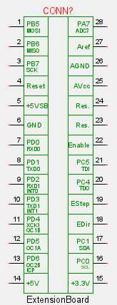
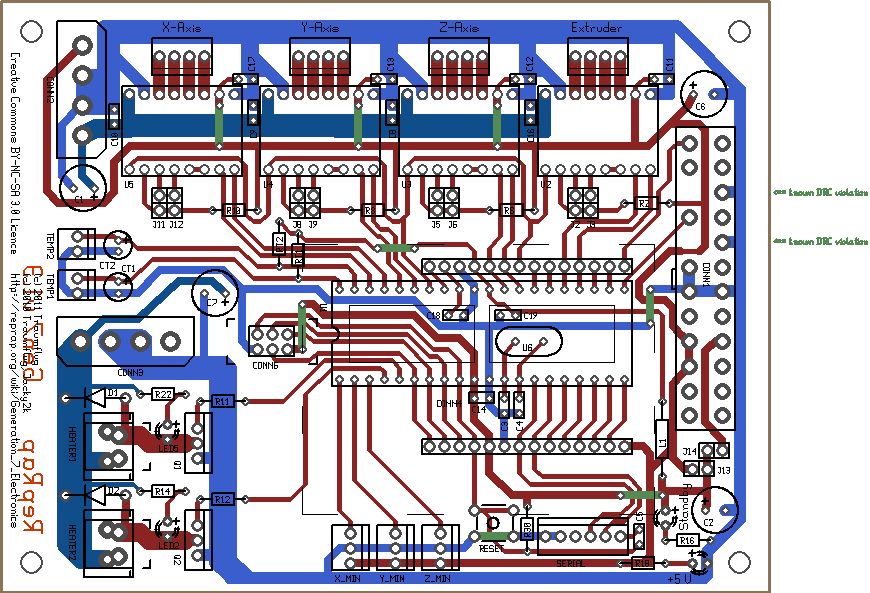
This is the plan for the next Gen7 release, it's already on Github:
As you see, besides a few enhancements on reliability (no close connection between GND for the MOSFETS and GND for the thermistors), there's now also an extension header. This header shall allow for everything which is desireable, but not essential, so people can start with a base board to get their RepRap running and add other stuff later:
- 3 max endstops
- I2C for a display
- switches for a keyboard
- SD card
- second extruder
- multi-color extruder
The last one is a bit tricky, as it may need up to four stepper motors. The plan is to have a common Enable and Dir line for all of them, along with a Step line for each of them. This way each motor can be driven independently, with only one additional pin for each motor. Perhaps even 7 motors if three pins are spread by a multiplexer chip.
Did I miss anything?
| Generation 7 Electronics | Teacup Firmware | RepRap DIY |
|
Re: Generation 7 Electronics Development April 04, 2012 10:00AM |
Admin Registered: 17 years ago Posts: 7,879 |
|
Re: Generation 7 Electronics Development April 04, 2012 10:38AM |
Admin Registered: 12 years ago Posts: 2,569 |
|
Re: Generation 7 Electronics Development April 04, 2012 02:10PM |
Registered: 14 years ago Posts: 3,742 |
Quote
Traumflug
- 3 max endstops
I think you MEAN:
- 3 MIN endstops
Bob Morrison
Wörth am Rhein, Germany
"Luke, use the source!"
BLOG - PHOTOS - Thingiverse
|
Re: Generation 7 Electronics Development April 05, 2012 03:11AM |
Registered: 12 years ago Posts: 290 |
A fan controll would be a perfect usecase for an extension board!!
Having all those free pins broken out and not dedicated for special purposes makes this board much more modular and extendable. For such applications a seperate 12V Output (maybe on an extra screw terminal?) would be nice!
Having all those free pins broken out and not dedicated for special purposes makes this board much more modular and extendable. For such applications a seperate 12V Output (maybe on an extra screw terminal?) would be nice!
|
Re: Generation 7 Electronics Development April 05, 2012 03:58AM |
Admin Registered: 17 years ago Posts: 7,879 |
A lot of people use a fan so I don't think it should be an extension. I use three! It only costs pennies to drive them and there is a big space between the heater outputs and the limit switch inputs for them to go. If people don't want them, then they don't have to fit the components as this is a home build board, so the cost is nothing.
[www.hydraraptor.blogspot.com]
[www.hydraraptor.blogspot.com]
|
Re: Generation 7 Electronics Development April 05, 2012 06:20AM |
Registered: 12 years ago Posts: 290 |
Unfortunaltey the ATMega644(P)/1284P doesn't offer as much I/O pins as a 1280/2560 does. So I think there should be as much free pins as possible for personal purposes.
As you said... it's a DIY board. Everyone who can solder a GEN7 would have no problem adding the needed components for a fan controll to a stripboard and plug it in! Pluging something in later on seems to me much more simple than desoldering predifined parts from a running hardware.
By the way... The space between the heater mosfets and the endstop inputs is reserved for the heatsinks on the mosfets in most cases. So you won't have that much space there. Another issue is the routing of one free pwm output.( maybe again on Topside?)
|
Re: Generation 7 Electronics Development April 05, 2012 04:26PM |
Registered: 13 years ago Posts: 7,616 |
Quote
nophead
A fan output or two?
Yupp, can be done on the extension board. With PWM.
[code=rhmorrison]I think you MEAN:
- 3 MIN endstops[/code]
Nope, I mean max endstops, because min endstops are already on the base board.
Quote
scuba
For such applications a seperate 12V Output (maybe on an extra screw terminal?) would be nice!
You'd put such a screw terminal on the extension board, of course.
| Generation 7 Electronics | Teacup Firmware | RepRap DIY |
|
Re: Generation 7 Electronics Development April 05, 2012 09:43PM |
Registered: 14 years ago Posts: 72 |
A couple of things to pay attention to when using N-FETs for low-side load switching (i.e. the N-FET connects the load to GND).
1) devices designed for high-current and low on resistance typically have significant gate capacitance (a few thousand pf). You need to drive the gate with a lot of current to turn them on / off fast (Igate = Cgate * dV/dt). If the fall / rise time of the gate voltage is slow then the NFET will heat up. You can't drive these types of NFETs directly from the IO pin of an micro-controller for example. The faster the PWM frequency the more that slow rise/fall time will contribute to NFET heating.
2) Make sure you look at the Vgs_th (gate-to-source threshold voltage) required to fully turn the NFET on. It is common for Vgs to be higher than the max IO voltage of the IO pin of logic gates (or micro-controllers). If you don't drive the gate to the right voltage then the NFET won't fully turn on and again you will get excessive heating in the device.
There are plenty of application notes from semiconductor companies that will explain these things. Take advantage of them.
TC


Sorry, only registered users may post in this forum.