Generation 7 Electronics Development
Posted by Traumflug
|
Re: Generation 7 Electronics Development April 07, 2012 10:25PM |
Registered: 13 years ago Posts: 632 |
I like it. Of course now I'm a bit bummed that my ultra new Gen7T is already out of date  . Anyway, I did have a couple comments.
I like that max endstops are gone, and motor connectors are standardised to the .1 inch connectors everyone else seems to be using. Compatibility is a good thing.
Would it be a good idea to change the bed/hot end power connector from molex to an atx +4 connector? That way you wouldn't need to solder wires to the board if you want to run a heated bed.
Why not lengthen the 5V jumper and route the serial lines more directly?
Is there a spot in the expansion header that is compatible with either SD RAMPS or sanquinololu SD card boards, or would that be difficult on this design? I think I looked at the older gen7/gen7T and figured out you could add a two pin header by the programming socket and get pin compatibility with the sanquinololu add-on SD card boards. I haven't looked at SDRAMPS
. Anyway, I did have a couple comments. I like that max endstops are gone, and motor connectors are standardised to the .1 inch connectors everyone else seems to be using. Compatibility is a good thing.
Would it be a good idea to change the bed/hot end power connector from molex to an atx +4 connector? That way you wouldn't need to solder wires to the board if you want to run a heated bed.
Why not lengthen the 5V jumper and route the serial lines more directly?
Is there a spot in the expansion header that is compatible with either SD RAMPS or sanquinololu SD card boards, or would that be difficult on this design? I think I looked at the older gen7/gen7T and figured out you could add a two pin header by the programming socket and get pin compatibility with the sanquinololu add-on SD card boards. I haven't looked at SDRAMPS
|
Re: Generation 7 Electronics Development April 09, 2012 06:15PM |
Registered: 13 years ago Posts: 7,616 |
Quote
I'm a bit bummed that my ultra new Gen7T is already out of date
Be assured, it isn't. I just think this TB6560 stuff still has some way ahead before it's fit for general usage. And I couldn't hold back longer with the enhancements around the thermistor.
Quote
Would it be a good idea to change the bed/hot end power connector from molex to an atx +4 connector? That way you wouldn't need to solder wires to the board if you want to run a heated bed.
I thought about this for v1.3 already and the result was, the ATX +4 connector (both pins) is specified for only marginally more than the Molex 4-pin ones. So I decided for compatibility with older PSUs.
Quote
Why not lengthen the 5V jumper and route the serial lines more directly?
I don't see an advantage here. Shorter bridges are easier to solder than longer ones and isolation routing is almost for free.
Quote
Is there a spot in the expansion header that is compatible with either SD RAMPS or sanquinololu SD card boards, or would that be difficult on this design?
All the required stuff is available on the extension board and Alfons3 as well as scuba designed a replicatable SD card thing already. So, no need to be compatible with industry manufactured XXX
Quote
TC
A couple of things to pay attention to when using N-FETs [...]
Well ... this is about the most discussed topic on this board. About every electronics engineer apparently has at least two opinions about MOSFET design, so I have some 20 different recommendations so far. None of the engineers can come up with clear design rules (formulas) or a schematic which is provenly better than the current one without being more expensive. "I did this and that and it works for me" or "you can read up on this topic here and there" is ... *ahem* ... isn't useful.
So, if you think you can design a MOSFET switch fast enough for 80 kHz, thick enough for 15 amps and with part costs less than $1 (that's about what the current design can do), please provide me a Gen7 schematic modified exactly the way you think it's right. I'll send you a milled copy then.
Edited 1 time(s). Last edit at 04/09/2012 06:33PM by Traumflug.
| Generation 7 Electronics | Teacup Firmware | RepRap DIY |
|
Re: Generation 7 Electronics Development April 09, 2012 10:05PM |
Registered: 14 years ago Posts: 72 |
Traumflug... I don't know why you are so put off by 'information' and why you think what I posted was 'opinion'.
If you do a few calculations based on the information I posted along with some basic knowledge of IC device IO parameters you should be able to determine that there is a simple zero-cost improvement you could make to your design. Benefit, less heating in the FETs you've already selected.
Hint... try a lower series gate resistor instead of the 1K you currently have in your schematic.
TC
|
Re: Generation 7 Electronics Development April 10, 2012 04:48AM |
Registered: 13 years ago Posts: 7,616 |
Quote
I don't know why you are so put off by 'information' and why you think what I posted was 'opinion'.
Because all these 20 recommendations are contradicting. If the calculations are that simple, please do them.
Quote
try a lower series gate resistor instead of the 1K you currently have in your schematic.
I think you're talking about R11/R12, which is 10 ohms. I had to find this the experimental way: [reprap.org] . And yes, I also got recommendations which said 1K is fine.
| Generation 7 Electronics | Teacup Firmware | RepRap DIY |
|
Re: Generation 7 Electronics Development April 10, 2012 09:54PM |
Registered: 14 years ago Posts: 72 |
The .pdf of the schematic posted in the GitHub repository has R11/R12 at 1K, thus my comment.
At 10 ohms your asking for more current from the AVR than the 20ma rating of the IO pins (no calculations needed - it's in the datasheet). To stay within the limits of the AVR's IO pins would need a 250 ohm resistor.
So, this goes back to my original post here. The design would benefit from a high current driver between the AVR and the gate of the FET that is capable of driving the capacitance of the gate with a low value series R. While this wouldn't be 'cheaper' (your criteria) it would be a design improvement.
Generally, I'm happy to try to help people (if I can) but every once in a while there are people that aren't receptive to being helped (and that's fine too). Since my posts seem to bother you I'll refrain from responding with additional information.
TC
|
Re: Generation 7 Electronics Development April 11, 2012 05:39AM |
Admin Registered: 17 years ago Posts: 7,879 |
The problem is using 80KHz PWM to drive something with a thermal time constant measured in second, crazy.
All I do is switch my bed on if the temperature is too low, else turn it off, in a 100 Hz interrupt. In that case I don't need high gate currents and the resistor can be high enough to not stress the micro.
[www.hydraraptor.blogspot.com]
All I do is switch my bed on if the temperature is too low, else turn it off, in a 100 Hz interrupt. In that case I don't need high gate currents and the resistor can be high enough to not stress the micro.
[www.hydraraptor.blogspot.com]
|
Re: Generation 7 Electronics Development April 11, 2012 06:42AM |
Registered: 13 years ago Posts: 7,616 |
Thanks for the opinions, TC and nophead. Agreed, there are "crazy" things going on. As much as I'd like to make a design electrically sane in all aspects, there are more constraints:
- Very popular electronics, notable RAMPS and Sanguinololu, use this (over)simplified design and the community says this is working well. "It works" also means "it's sane" for most RepRappers. So, if one would enhance a design without visible benefit, people would tend to choose the cheaper variant. Perhaps not because of a 3-cent resistor and two solder points alone, but the tendency exists.
- Coming up with a design not capable of doing 80 kHz PWM is a recipe for failure, because people upload firmwares without even looking into the config. Think what happens if a few posts appear like "this new firmware works great on my RAMPS, but it has blown the MOSFETs of my Gen7". That's pretty much the same as "If you want the latest features, avoid a Gen7".
- Also firmware related, one has not only to design a proper circuitry, but also to modify and maintain a dozen or more firmwares. Look at how long it took until mainstream firmwares started to accept running at a 20 MHz CPU clock. Over a year! Despite having more processing speed is a clear benefit, I had many many discussions with people trying to explain me 16 MHz is more than one will ever need.
- A bad excuse, I'm a mechanical engineer and not an electrical one. For everything beyond ohm's law I can only copy what others do. Gen7 was started to make electronics replicatable and to develop processes allowing PCB printing.
That said, I hope this 20 mA rating of the ATmega (my data sheet says 40 mA on page 325) output means 20 mA on average.
| Generation 7 Electronics | Teacup Firmware | RepRap DIY |
|
Re: Generation 7 Electronics Development June 04, 2012 11:54AM |
Hello Traumflug!
I want to optimize Gen7 v1.4 for the toner transfer method and tried to follow your tutorial at:
[reprap.org]
Since I don't have any experience in designing or etching pcbs I encountered some problems:
-"Remove all tracks on this layer ( = all light blue ones = all of the GND net minus vias and bridges, find the net with Menu -> Window -> Netlist)."
I have deleted all the light blue tracks, however I don't understand the part about the Netlist. "GND net minus vias and bridges" - I can't find any "vias" or "bridges" in the lists.
As I do an "optimize rats nest" after drawing the rect nothing seems to happen. Is this correct?
-"For pins and pads you actually want to connect to the ground plane, set a Thermal". I hope this isn't a stupid question: Which Pins or Pads have to be connected to the ground plane?
In fact I would also be pleased about an already optimized Gen7 v1.4 board layout which I only have to print out, but I couldn't find it.
Thank you for your great instructions on assembling the Gen7 1.4 board by the way!!
|
Re: Generation 7 Electronics Development June 05, 2012 06:44AM |
Registered: 13 years ago Posts: 7,616 |
gEDA has changed quite a bit since these instructions were written. I've just updated the wiki in the hope this answers your questions. Feel free to enhance the wiki further or to post here again, if things are still unclear.
Maintaining several versions of the same thing is always error-prone and so far nobody wrote a script to create this GND-plane version automatically.
Quote
In fact I would also be pleased about an already optimized Gen7 v1.4 board layout which I only have to print out, but I couldn't find it.
Maintaining several versions of the same thing is always error-prone and so far nobody wrote a script to create this GND-plane version automatically.
| Generation 7 Electronics | Teacup Firmware | RepRap DIY |
|
Re: Generation 7 Electronics Development June 12, 2012 04:00PM |
Registered: 12 years ago Posts: 14 |
|
Re: Generation 7 Electronics Development June 13, 2012 04:18AM |
Registered: 13 years ago Posts: 7,616 |
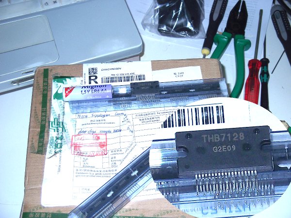
Interesting chip, this A3992.
Instead of using STEP and DIR, you change a stepper motor's status by sending 56 bits of data for each status. Each step requires a new status.
Looking at the serial line timing diagram at the bottom of page 9, minimum clock time is 40 ns + 40 ns = 80 ns, or 12.5 MHz. For 56 bits, a write cycle would be about 5 microseconds, resulting in a maximum step rate of 200 kHz. Surprisingly fast. Always assuming I understood this diagram correctly.
The challenge would likely be to make the ATmega calculate and send out this data at a rate of at least 20kHz, simultanously for at least 3 steppers.
| Generation 7 Electronics | Teacup Firmware | RepRap DIY |
|
Re: Generation 7 Electronics Development June 13, 2012 09:14AM |
Registered: 12 years ago Posts: 14 |
Thank you ,
That is very interesting ( I admitt i didn't enter in details like you just did ). I just noticed there was an experimental card using it.
I love the spirit of gen7, because it's the real reprap style ( do it simply , cheap and with home tools ), I try in spare time to look for nice upgrades .
So you think it would be interesting to look further ? I think with this kind of chip, we could make the complete gen7 with steper drivers for cheaper and still simple to do ( no need to solder cms
Serge
That is very interesting ( I admitt i didn't enter in details like you just did ). I just noticed there was an experimental card using it
.I love the spirit of gen7, because it's the real reprap style ( do it simply , cheap and with home tools ), I try in spare time to look for nice upgrades .
So you think it would be interesting to look further ? I think with this kind of chip, we could make the complete gen7 with steper drivers for cheaper and still simple to do ( no need to solder cms
Serge
|
Re: Generation 7 Electronics Development July 07, 2012 04:57PM |
Registered: 13 years ago Posts: 7,616 |
For those interested in upgrading from a Gen7 v1.3.1 to a Gen7 v1.4, I've put together a list of the required parts:
Parts for upgrading from v1.3.1 to v1.4
Parts for upgrading from v1.3.1 to v1.4
| Generation 7 Electronics | Teacup Firmware | RepRap DIY |
|
Re: Generation 7 Electronics Development August 01, 2012 12:56PM |
Registered: 13 years ago Posts: 7,616 |

|
Re: Generation 7 Electronics Development August 03, 2012 07:38PM |
Registered: 13 years ago Posts: 632 |

|
Re: Generation 7 Electronics Development August 18, 2012 06:37PM |
Registered: 13 years ago Posts: 7,616 |
Generation 7 Electronics v1.4.1 is released.
This release should put an end to all the MOSFET discussions. There was noteworthy research (for RepRap measures) to find the facts: [reprap.org] . Also result of this research is, heated beds should be run at low PWM frequencies, like 50 or 80 Hz. Teacup supports this, it's even the default. To what I've heard, other firmwares don't even support PWM for the heated bed, so they're safe.
Changes & Links: [reprap.org]
Wiki page: [reprap.org]
Upgrade instructions: [reprap.org]
Have fun!
| Generation 7 Electronics | Teacup Firmware | RepRap DIY |
|
Re: Generation 7 Electronics Development October 10, 2012 08:48AM |
Registered: 13 years ago Posts: 7,616 |
October 10th, 2010 was the day when the Gen7 wiki page was created.
| Generation 7 Electronics | Teacup Firmware | RepRap DIY |
|
Re: Generation 7 Electronics Development October 10, 2012 12:41PM |
Registered: 13 years ago Posts: 632 |
|
Re: Generation 7 Electronics Development October 11, 2012 06:49AM |
Registered: 13 years ago Posts: 7,616 |
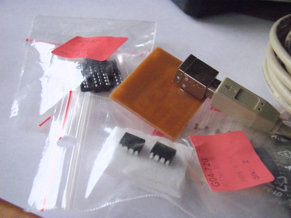
Oh, there's a birthday present:
A PCB with a few bags. One of the bags has the smallest available through-hole AVR CPU inside. Looks like this isn't about unpackaging something, it's about assembling.

A PCB with a few bags. One of the bags has the smallest available through-hole AVR CPU inside. Looks like this isn't about unpackaging something, it's about assembling.
| Generation 7 Electronics | Teacup Firmware | RepRap DIY |
|
Re: Generation 7 Electronics Development October 11, 2012 04:38PM |
Registered: 12 years ago Posts: 159 |
Yeeeeeeeh
Long life the GEN7
-----------------------------------------------------------------------------------------------------------
blog Paoparts
Long life the GEN7
-----------------------------------------------------------------------------------------------------------
blog Paoparts
|
Re: Generation 7 Electronics Development October 11, 2012 05:07PM |
Registered: 12 years ago Posts: 1,236 |

|
Re: Generation 7 Electronics Development October 12, 2012 07:50AM |
Registered: 13 years ago Posts: 7,616 |
Hehe. USB powered heated bed, making the entire printer running off USB, making all this power supply fuzz obsolete ... Now, that's a nice dream
There's a layout on Github which should help me to get this soldered. I guess the "interesting" things start after that. For example: how to program an ATtiny ...
There's a layout on Github which should help me to get this soldered. I guess the "interesting" things start after that. For example: how to program an ATtiny ...

| Generation 7 Electronics | Teacup Firmware | RepRap DIY |
|
Re: Generation 7 Electronics Development October 12, 2012 08:25AM |
Registered: 11 years ago Posts: 121 |
|
Re: Generation 7 Electronics Development October 13, 2012 06:55AM |
Registered: 13 years ago Posts: 7,616 |
I hope I can get serial commnications established over SPI somehow. As you probably know, the ATtiny has no hardware RS232 protocol built in and doing this in software is pretty slow (tha japanese page talks about 4800 baud maximum).
One question to be solved: who is the SPI master? Is it the ATtiny, the ATmega can't talk to other SPI devices (e.g. SD card), right? Is it the ATmega, it has to poll the ATtiny all the time.
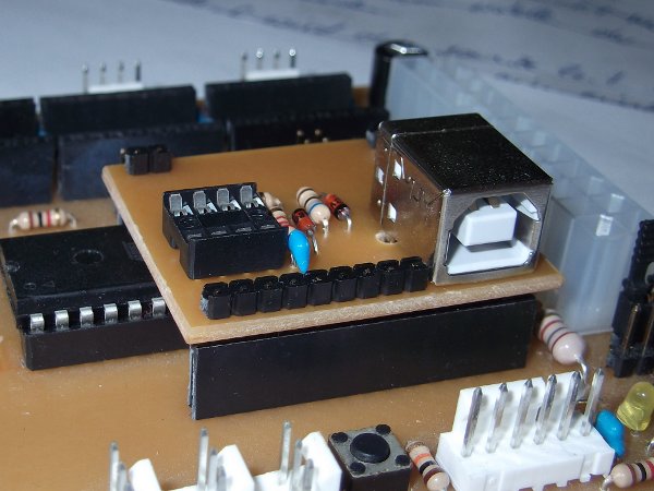
Anyways, after assembly to board now looks like this:
One question to be solved: who is the SPI master? Is it the ATtiny, the ATmega can't talk to other SPI devices (e.g. SD card), right? Is it the ATmega, it has to poll the ATtiny all the time.
Anyways, after assembly to board now looks like this:

| Generation 7 Electronics | Teacup Firmware | RepRap DIY |
|
Re: Generation 7 Electronics Development October 13, 2012 07:04AM |
Registered: 11 years ago Posts: 121 |
|
Re: Generation 7 Electronics Development October 13, 2012 07:37AM |
Registered: 13 years ago Posts: 7,616 |
It's nice you have your ATtiny working, Peter. So far I can't find any setup instructions. Did I miss something?
| Generation 7 Electronics | Teacup Firmware | RepRap DIY |
|
Re: Generation 7 Electronics Development October 13, 2012 07:48AM |
Registered: 11 years ago Posts: 121 |
Not much no.
1. Download [www.recursion.jp]
2. Extract
3. Use AVRDude or WinAVR to burn the firmware
3.1 ATTiny45:
burn ./tiny45/default/cdctiny45.hex to the ATTiny45
For example (fuse bits are correct in this command)
avrdude -cusbtiny -pt45 -U flash:w:cdctiny85.hex -U lfuse:w:0xf1:m -U hfuse:w:0xce:m -U efuse:w:0xff:m
3.2: ATTiny2313:
burn ./tiny2313/default/cdc2313-16.hex (for 16mhz xtal. The 16mhz version has DTR (for autoreset) - so don;t use the 12Mhz)
./avrdude/avrdude -C ./avrdude/avrdude.conf -cusbtiny -pt2313 -U flash:w:cdc2313-16.hex
./avrdude/avrdude -C ./avrdude/avrdude.conf -cusbtiny -pt2313 -U lfuse:w:0xff:m -U hfuse:w:0xdf:m -U efuse:w:0xff:m
You can use an arduino as ISP (note that I have no success with default baud rate, and always drop back to 9600), or a USBtinyISP (best option if you have one around)
If you want to spend a few hours today productively, may I suggest you build my AVR-Burner PCB? Has a onboard USBtiny programmer and accompanying Linux Zenity script which puts all this trouble into a GUI...
Or just use the software (with either programmer and target board or ICSP header)
Eagle files (single sided PCB for home making) and Software here: [github.com]
Here's my 2313 based USB-Serial as well - with FTDI pinout header - works on Gen7
[github.com]
Edited 1 time(s). Last edit at 10/13/2012 07:52AM by peter6960.
|
Re: Generation 7 Electronics Development October 13, 2012 07:55AM |
Registered: 13 years ago Posts: 7,616 |
|
Re: Generation 7 Electronics Development October 13, 2012 12:33PM |
Registered: 13 years ago Posts: 7,616 |
Hmm. So far I'm not exactly successful:
I resoldered pin 1 to the reset pin, still no change. Obviously I'm missing something.
Edit: what I've done so far is written down here: [reprap.org]
Edited 1 time(s). Last edit at 10/13/2012 01:04PM by Traumflug.
$ avrdude -c avrispv2 -p attiny85 -P /dev/ttyACM0 -B 100 -v -F
...
avrdude: stk500v2_command(): command failed
avrdude: initialization failed, rc=-1
avrdude: AVR device initialized and ready to accept instructions
avrdude: Device signature = 0x000000
avrdude: Yikes!  Invalid device signature.
...
I resoldered pin 1 to the reset pin, still no change. Obviously I'm missing something.
Edit: what I've done so far is written down here: [reprap.org]
Edited 1 time(s). Last edit at 10/13/2012 01:04PM by Traumflug.
| Generation 7 Electronics | Teacup Firmware | RepRap DIY |
|
Re: Generation 7 Electronics Development October 13, 2012 01:36PM |
Registered: 11 years ago Posts: 121 |


Sorry, only registered users may post in this forum.